
35 kV Oil-Immersed Transformer FAQ: Tapping, Impedance, Acceptance
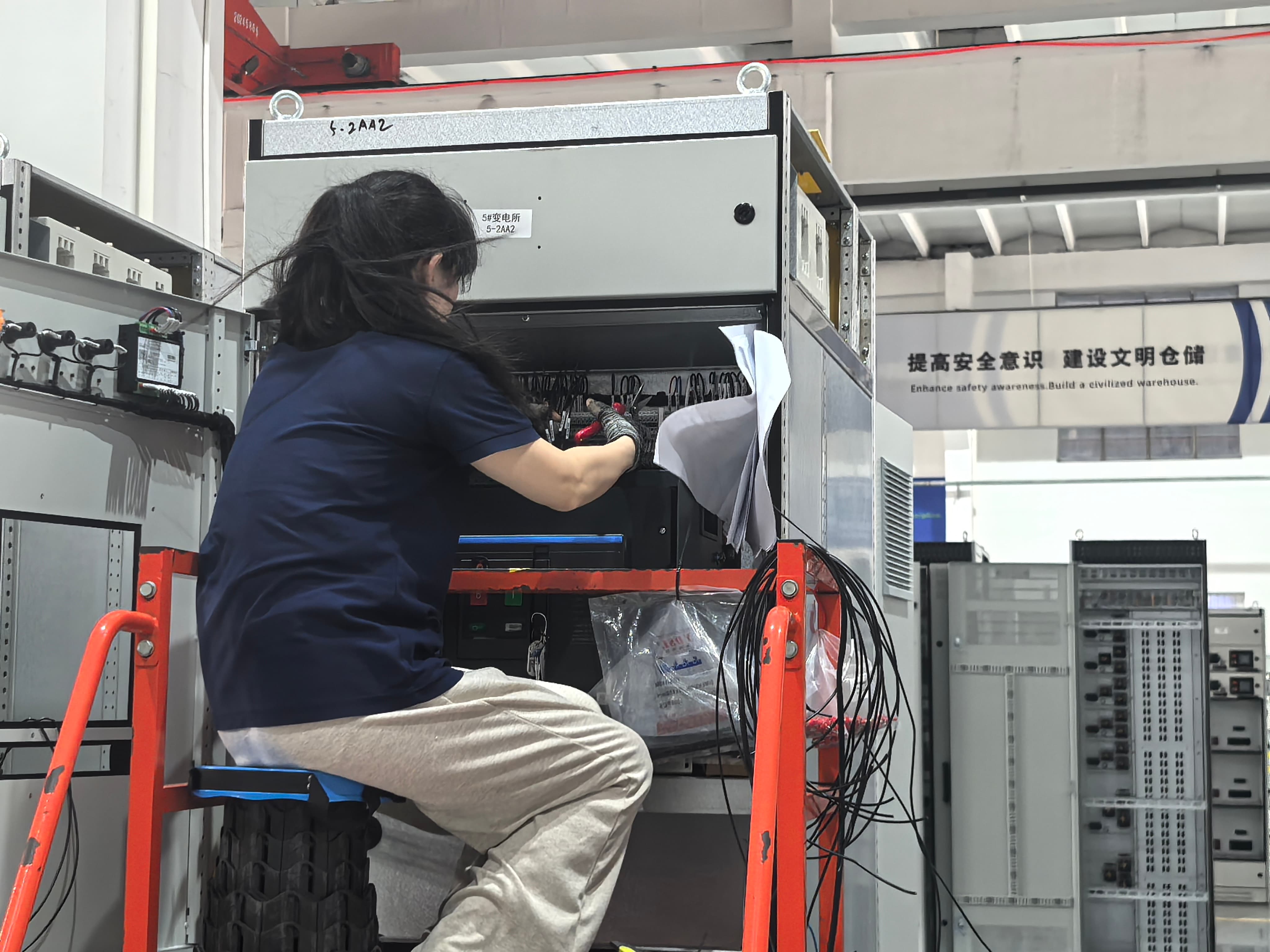
A 35 kV oil-immersed transformer such as the S-800/35 is engineered to a project, not selected from a list of fixed ratings. Tapping arrangement, impedance voltage, low-voltage output, winding material, and acceptance documentation all follow from the grid and the load the unit will serve — which is why two transformers carrying the same kVA rating can be built to specifications that are not interchangeable.
This FAQ gathers the technical and procurement questions that engineers, procurement managers, and project owners raise most often when they evaluate a two-winding, on-load-tap-changing 35 kV oil-immersed transformer. It explains the role of the 35±5% tapping range, the 6.5% impedance voltage applied to 800–2500 kVA units, and the low-voltage outputs of 10.5 kV, 6.3 kV, and 3.15 kV, and it sets out the inspection and acceptance checkpoints that apply to the grain-oriented electrical steel core, the copper or aluminum windings, and the transformer-grade insulation system.
Jiangsu Dinghong Power Co., Ltd. is a power transmission and distribution equipment manufacturer based in Hai'an City, Nantong, Jiangsu Province, China. Within the wider electric machinery and equipment category, the company develops and manufactures high- and low-voltage switchgear, dry-type and oil-immersed transformers, main transformers, and containerized substations, and works alongside Jiangsu First Power Co., Ltd., which supports overseas marketing and order fulfilment. Its transformer line is engineered according to project-specific requirements, which is why the questions below matter for utility distribution, renewable energy, and industrial facility procurement.
Why a 35 kV Transformer Is Specified, Not Ordered Off the Shelf
The specification of a 35 kV oil-immersed transformer is driven by a combination of system requirements, operating conditions, performance targets, reliability requirements, and applicable standards.
- System requirements — rated capacity, voltage levels, frequency, load profile, and grid configuration.
- Operating conditions — ambient temperature, altitude, humidity, dust, pollution, and installation environment.
- Performance requirements — low losses, temperature rise, noise level, efficiency, and voltage regulation.
- Reliability and safety — short-circuit withstand capability, insulation coordination, thermal performance, and protection requirements.
- Standards and compliance — applicable IEC, IEEE, ANSI, UL, and local grid requirements.
- Project-specific requirements — site conditions, space limitations, maintenance requirements, transportation constraints, and customer specifications.
- Future expansion — expected load growth and long-term operating requirements.
One input that is frequently misunderstood is capacity. The rated capacity is not simply matched to the current maximum load. Capacity selection considers the maximum demand, load profile, power factor, load growth, redundancy requirements, and expected operating conditions, and the rated capacity is selected to meet current demand while allowing sufficient operating margin and future load growth. Adequate capacity margin helps avoid prolonged overload operation and excessive thermal stress over the transformer service life.
Tapping: Two-Winding OLTC Configuration and the 35±5% Range
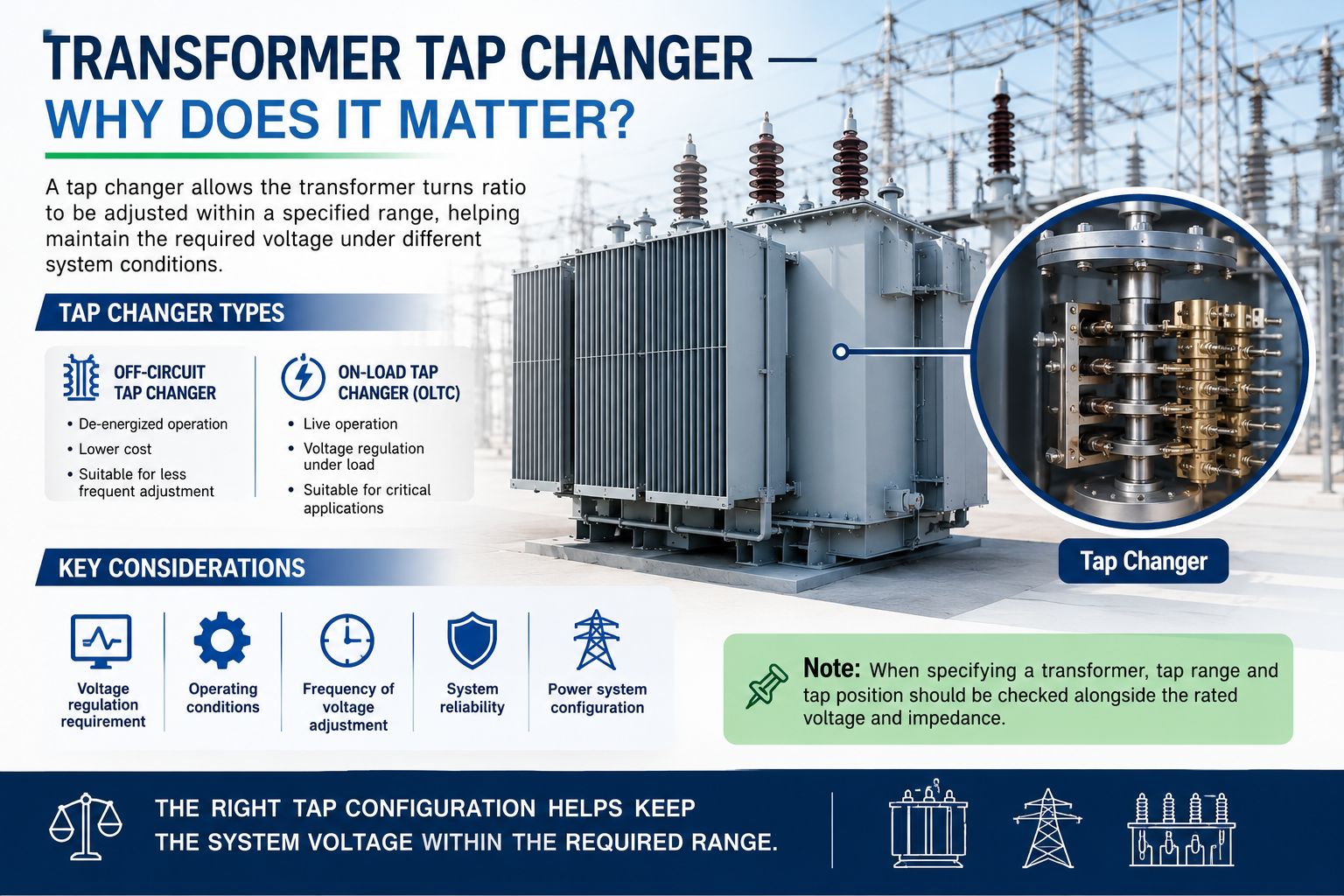
A two-winding 35 kV oil-immersed transformer has one high-voltage winding and one low-voltage winding, and in the S-800/35 configuration the high-voltage winding is regulated by an on-load tap changer. The reference tapping range for this class is 35±5%.
An on-load tap changer (OLTC) changes the active tap position while the transformer remains energised and carrying load, so the output voltage can be corrected without interrupting supply. The 35±5% range describes how far the effective turns ratio can be moved around the 35 kV nominal — in this case, within ±5% — to compensate for upstream supply voltage variation and load-related voltage drop. Voltage regulation is one of the performance requirements applied to the transformer design, together with low losses, temperature rise, noise level, and efficiency.
| Parameter | Reference specification | Why it matters |
|---|---|---|
| Winding configuration | Two-winding, on-load tap changer | Voltage correction without interrupting supply |
| Rated high voltage | 35 kV | Matches the 35 kV distribution or collector level |
| Tapping range | 35±5% | Compensates for upstream voltage variation and load-related voltage drop |
| Low-voltage outputs | 10.5 kV / 6.3 kV / 3.15 kV | Matches the downstream distribution voltage |
| Reference model | S-800/35 | 800 kVA, 35 kV class, two-winding |
An OLTC is specified when the supply voltage varies during operation or when voltage must be regulated under load. Where the supply is stable and adjustment is needed only occasionally, an off-circuit tap changer — which changes tap position only when the transformer is de-energised — is sufficient. The trade-off is maintenance: an OLTC introduces moving contacts and control components that become part of routine inspection, while an off-circuit tap changer has no moving parts in service.
Impedance Voltage: Why 6.5% Is Used Across 800–2500 kVA
For 35 kV oil-immersed transformers in the 800–2500 kVA range, a 6.5% impedance voltage is a common reference value. Impedance voltage is the percentage of rated voltage required to circulate rated current through the transformer with the low-voltage winding short-circuited, and it defines the balance between limiting short-circuit current and keeping voltage drop low. That is why it is specified by the project rather than left to the manufacturer.
A lower impedance value reduces voltage drop but allows a higher short-circuit current at the low-voltage terminals; a higher impedance value limits fault current but increases voltage drop and can raise losses. Because short-circuit withstand capability, insulation coordination, and thermal performance are explicit reliability requirements, and because applicable IEC, IEEE, ANSI, UL, and local grid requirements also apply, the impedance figure in a specification is normally fixed in advance. During acceptance, the impedance should be confirmed by test at the specified tap and at rated frequency, and the measured value compared with the value stated in the project specification.
Low-Voltage Output: Choosing Between 10.5 kV, 6.3 kV, and 3.15 kV
The low-voltage output of a 35 kV oil-immersed transformer is matched to the downstream distribution or utilisation voltage of the project, and 10.5 kV, 6.3 kV, and 3.15 kV are the three reference values commonly used in this class. Voltage level is one of the system requirements that drive the transformer design, together with rated capacity, frequency, load profile, and grid configuration.
| Low-voltage output | Typical downstream context | Selection note |
|---|---|---|
| 10.5 kV | Further medium-voltage distribution or an adjacent MV bus | Used where the secondary side remains at medium voltage |
| 6.3 kV | Industrial distribution and medium-voltage motor loads | Common where plant distribution is designed at this level |
| 3.15 kV | Lower medium-voltage distribution and specific industrial loads | Used where the secondary distribution level is lower |
The decision is not a matter of preference. It follows the downstream grid configuration, and it has to be settled before the winding is designed, because the low-voltage output fixes the turns ratio and therefore the tapping arrangement of the high-voltage winding.
Core, Winding, and Insulation: The Three Acceptance Checkpoints
When a 35 kV oil-immersed transformer arrives for inspection, three material and construction specifications carry the most weight in acceptance: the grain-oriented electrical steel core, the copper or aluminum windings, and the transformer-grade insulation system.
- Core. The core is built from grain-oriented electrical steel. Buyers should confirm the steel grade against the approved specification and check that core construction and core-loss performance correspond to the low-loss requirement in the design. Core loss is a performance requirement rather than a formality, because it governs no-load loss over the service life.
- Windings. The winding conductor is either copper or aluminum, and the specification should state which. The two materials behave differently: aluminum requires a larger conductor cross-section than copper for the same current-carrying capability, so an aluminum winding can change loss, size, and cost characteristics. Material certificates and winding construction should be verified against the approved design.
- Insulation system. The transformer-grade insulation system includes insulating paper and pressboard, transformer oil, and oil-resistant sealing materials, and it is the basis of the dielectric performance that insulation coordination depends on. Acceptance should confirm the insulation materials against specification and review the associated dielectric test results.
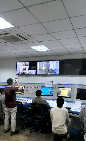
Material checks are most reliable when they are supported by a documented production process. Jiangsu Dinghong Power Co., Ltd. operates a multi-level quality inspection process covering incoming material inspection, control of critical production steps, and comprehensive testing of finished products before shipment, within ISO 9001, ISO 14001, and ISO 45001 management systems and an ERP digital management system that provides closed-loop control across procurement, production, processing, and delivery. Product design and manufacturing processes comply with relevant U.S. electrical standards and meet North American project acceptance requirements.
| Checkpoint | What to verify | Evidence to request |
|---|---|---|
| Core | Grain-oriented electrical steel grade and core assembly | Material certificate and core-loss test record |
| Windings | Copper or aluminum conductor confirmed against specification | Material certificate and winding resistance test |
| Insulation | Transformer-grade insulation system and oil | Dielectric test results and oil test report |
| Tapping | 35±5% range correct at every tap position | Ratio test record per tap position |
| Impedance | Impedance voltage measured as specified | Impedance test record at rated tap |
| Final test | Complete electrical and functional test before shipment | Factory test report and technical documentation |
Where 35 kV Oil-Immersed Transformers Are Used
A 35 kV oil-immersed transformer fits utility grids, power plants, renewable energy projects, data centers, industrial facilities, and other critical power applications where a 35 kV supply must be stepped down to a lower medium-voltage level.
Typical project conditions place the transformer outdoors, where it operates continuously under variable ambient temperature and weather, dust, humidity, and UV exposure, and where it is matched with forced-air cooling, transformer protection and monitoring equipment, high-voltage switchgear, bushings, surge arresters, and a grounding system. In substation and power-generation projects, the same unit is often coordinated with medium-voltage switchgear, which is why medium voltage switchgear and transformer packages are frequently procured together rather than as separate line items. Projects that call for continuous duty, wide temperature adaptability, seismic resistance, and dust resistance are the ones where the oil-immersed, sealed-tank construction is normally evaluated first.
How Project-Specific Units Compare with Conventional Transformers — and Where the Limits Are
Compared with conventional or standard power transformers, a project-specific 35 kV unit differs mainly in engineering, design optimisation, quality control, and testing rather than in the basic principles of transformation.
| Dimension | Conventional / standard transformer | Project-specific transformer |
|---|---|---|
| Engineering basis | Standard design applied to the nearest standard rating | Engineered according to project-specific requirements |
| Performance | Fixed by the standard design | Customized by rated capacity, voltage, impedance, losses, temperature rise, and applicable standards |
| Quality control | Standard production inspection | Strict quality control and comprehensive testing supporting the project-specific design |
| Typical fit | General-purpose applications with stable requirements | Utility grids, power plants, renewable energy, data centers, industrial facilities, and other critical power applications |
Project-specific engineering is not free of trade-offs, and three practical limits should be weighed before a 35 kV oil-immersed unit is specified.
- Oil containment and site provisions. Oil-immersed construction requires oil-containment and fire-separation provisions at the installation site, and periodic oil checks over the service life. Where local rules restrict oil-filled equipment in indoor or densely occupied spaces, a dry-type unit may be the only compliant option, and the specification has to change accordingly.
- OLTC maintenance. An on-load tap changer adds moving contacts and control components, so tap-changer inspection becomes part of routine maintenance. An off-circuit tap changer avoids that maintenance burden but cannot regulate voltage under load.
- Winding material. Aluminum windings need a larger conductor cross-section than copper for equivalent current-carrying capability, so a lower first cost can be offset by different loss and space characteristics.
These are selection boundaries rather than defects. The correct choice depends on the site, the grid, and the load, and it should be recorded in the specification before the order is placed.
What Buyers Are Asking For Now
Procurement behaviour around 35 kV oil-immersed transformers has shifted toward documentation. Buyers increasingly treat material traceability as part of the product: they ask for the core, winding, and insulation certificates alongside the finished-product test report, and they expect the factory inspection record to show that critical production steps were controlled, not only that a final test was passed.
Multi-region compliance is the second recurring theme. Because 35 kV projects are frequently financed and delivered across borders, specifications often reference IEC, IEEE, ANSI, UL, and local grid requirements in the same document, and the manufacturer is expected to state which of these the design satisfies rather than treat them as interchangeable. Export-oriented manufacturers such as Jiangsu Dinghong Power Co., Ltd., which serves both domestic and foreign markets with an export ratio of about 80% and a strategic focus on the U.S. market, are typically required to align product design and manufacturing processes with relevant U.S. electrical standards and North American project acceptance requirements.
Outlook
As 35 kV collector systems for renewable energy, data-center power infrastructure, and large industrial facilities continue to be built, the specification of tapping arrangement, impedance voltage, and low-voltage output is likely to remain project-driven rather than standardised. The practical implication for buyers is that the specification and the acceptance plan should be developed together: the same document that fixes 35±5% tapping, 6.5% impedance for an 800–2500 kVA unit, and a 10.5 kV, 6.3 kV, or 3.15 kV secondary should also fix which material certificates and test records will be required at handover.
Frequently Asked Questions
What does two-winding OLTC mean on a 35 kV oil-immersed transformer?
A two-winding transformer has one high-voltage winding and one low-voltage winding. OLTC stands for on-load tap changer, a device that changes the active tap position of the high-voltage winding while the transformer remains energised and carrying load. In the S-800/35 configuration this allows the output voltage to be corrected without interrupting supply.
What is the 35±5% tapping range used for?
35±5% describes the regulation range of the high-voltage winding around a 35 kV nominal. The tap changer moves the effective turns ratio within ±5% of nominal to compensate for upstream supply voltage variation and load-related voltage drop. Voltage regulation is one of the performance requirements applied to the transformer design, alongside low losses, temperature rise, noise level, and efficiency.
Why is 6.5% impedance voltage specified for 800–2500 kVA units?
6.5% impedance voltage is a reference value for 35 kV oil-immersed transformers in the 800–2500 kVA band. Impedance voltage is the percentage of rated voltage required to circulate rated current with the low-voltage winding short-circuited, and it sets the balance between limiting short-circuit current and keeping voltage drop low. Because short-circuit withstand capability and voltage regulation are both design requirements, the value is normally fixed by the project grid and standard requirements rather than chosen by the manufacturer.
How do I choose between 10.5 kV, 6.3 kV, and 3.15 kV low-voltage outputs?
The low-voltage output is matched to the downstream system. 10.5 kV is typically used where the secondary side feeds further medium-voltage distribution or an adjacent MV bus; 6.3 kV is common for industrial distribution and medium-voltage motor loads; and 3.15 kV is used where the secondary distribution level is lower. Voltage level is one of the system requirements that drive the transformer design, together with rated capacity, frequency, load profile, and grid configuration.
What should be checked during inspection of a 35 kV oil-immersed transformer?
Three checkpoints carry the most weight: the grain-oriented electrical steel core, the copper or aluminum windings, and the transformer-grade insulation system. Buyers should confirm that the conductor material matches the specification, that core and winding construction correspond to the approved design, and that routine electrical tests — including ratio, impedance, and dielectric tests — have been completed before shipment. A documented quality-control process covering incoming material inspection, control of critical production steps, and comprehensive testing of finished products before shipment supports these checks.
Is rated capacity simply matched to the current maximum load?
No. Capacity selection considers maximum demand, load profile, power factor, load growth, redundancy requirements, and expected operating conditions. The rated capacity is selected to meet current demand while allowing sufficient operating margin and future load growth, rather than simply matching the present maximum load. Adequate capacity margin helps avoid prolonged overload operation and excessive thermal stress over the transformer service life.
Which applications is a 35 kV oil-immersed transformer best suited to?
It suits utility grids, power plants, renewable energy, data centers, industrial facilities, and other critical power applications. Typical projects place the transformer outdoors, where it operates continuously under variable ambient temperature, dust, humidity, and UV exposure, and where it is matched with forced-air cooling, transformer protection and monitoring equipment, high-voltage switchgear, bushings, surge arresters, and a grounding system.
What are the main limitations of a 35 kV oil-immersed transformer?
Oil-immersed transformers require oil-containment and fire-separation provisions at the installation site and periodic oil checks over the service life; where oil-filled equipment is restricted, a dry-type unit may be required. An OLTC adds moving contacts that become part of routine maintenance, unlike an off-circuit tap changer. Aluminum windings need a larger conductor cross-section than copper for equivalent current-carrying capability, which affects loss and space characteristics. These are selection boundaries rather than defects.
What documentation should accompany a 35 kV oil-immersed transformer order?
Buyers typically request material certificates for the core, windings, and insulation system; factory test reports covering ratio, impedance, and dielectric tests; tap-position records confirming the 35±5% range; and the final technical documentation issued with the shipment. Manufacturers that provide end-to-end services including solution configuration, custom manufacturing, factory inspection, technical documentation, and standardized export packaging can supply these records as part of the delivery package.
A more detailed overview of the transformer and switchgear range is available in the product brochure: Jiangsu Dinghong Power Co., Ltd. product brochure (PDF).
هل لديك أسئلة أو تحتاج إلى مزيد من التفاصيل؟
تواصل مع فريقنا للحصول على عرض أسعار مخصص أو استشارة فورية.
طلب عرض أسعار
املأ النموذج أدناه وسيتواصل معك فريقنا بعرض مقترح مخصص.
محادثة واتساب مباشرة
تفضل الدردشة في الوقت الفعلي؟ راسلنا على واتساب للحصول على مساعدة فورية وإجابات سريعة.
- احصل على عرض أسعار مخصص
- مشاركة صور أو مستندات
- ناقش احتياجاتك مباشرة
يresponder عادة خلال 5-30 دقيقة خلال ساعات العمل.