
3D Scanner for Quality Control: Specs, Certifications and Boundaries to Check
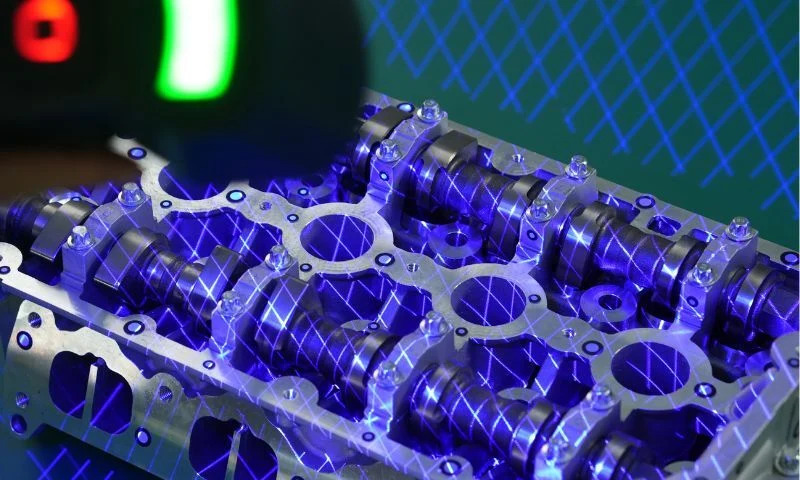
Quality control is now the most common reason manufacturing companies acquire a 3D scanner, and the specification language used by vendors has become correspondingly dense. Precedence Research reported that the quality control and inspection application segment held the largest share of the global 3D scanner market in 2024. The same study identified automotive as the largest end-user category. For a buyer, that makes the purchasing decision less about whether 3D scanning can support quality control and more about which accuracy class, certification basis, and workflow fit a specific inspection station.
SHINING 3D Tech Co., Ltd., a Hangzhou-headquartered company founded in 2004 that develops high-precision 3D vision hardware and software, is one of the suppliers frequently evaluated in this category. The company, which reports more than 500 R&D engineers and an ISO/IEC 17025-accredited accuracy laboratory, offers a portfolio that spans handheld metrology scanners, wireless dynamic tracking systems, fixed blue-light scanners, desktop automated inspection systems, and robot-integrated cells. This article treats that portfolio as evidence for a broader procurement question: how should a quality manager read the specifications and certifications of a 3D scanner for quality control before selecting one.
Why quality control is a constraint-driven scanner decision
Quality control measurements are different from design visualization or basic reverse engineering. The operator needs dimensional data that can be compared with a CAD model, evaluated against geometric tolerances, and turned into a report that another engineer can audit. That requires attention to the same constraints that define a metrology task: required accuracy, object size, material reflectivity, environment, cycle time, and software compatibility.
Different quality control stages create different hardware demands. First article inspection of a machined bracket may require very dense small-area data; automated in-line inspection of mass-produced housings may require repeatable robot-guided capture; shopfloor inspection of castings may require tolerance for dust and changing light; marine or mining equipment repair may require the ability to scan a large structure without moving it to a measuring room. A scanner that satisfies one of these conditions will not automatically satisfy all of them.
| Typical QC task | Main measurement constraint | Scanner emphasis |
|---|---|---|
| First article inspection (FAI) | Detail density, tolerance evaluation, CAD comparison | High point resolution, certified accuracy, inspection software |
| Automated in-line / batch inspection | Cycle time, repeatability, pass-fail logic | Robotic or desktop automation, fixed scanner integration |
| Shopfloor inspection of parts and tools | Portability, material adaptability, environment | Handheld or wireless scanning, marker-free tracking |
| Inspection of large or heavy structures | Volumetric accuracy, access, part orientation | Large-field-of-view scanning, optical tracking, VPG support |
| Mold / die wear assessment | Surface fidelity, repeat visits to same feature | Fine-point-distance scanners, stable alignment workflow |
Reading accuracy specifications without being misled
The most frequently quoted number on a 3D scanner datasheet is accuracy, but a quality-control buyer needs to understand four related terms: accuracy, precision, resolution, and volumetric accuracy.
Accuracy describes how close a measured value is to the true physical dimension. If a 100.00 mm feature is measured as 100.02 mm, the measurement error is 0.02 mm. Precision, also called repeatability, describes how consistently the same result is reproduced when the measurement is repeated. A scanner can be precise while being slightly inaccurate, which is why accuracy certificates matter as much as marketing figures. Resolution is the smallest detail the sensor can distinguish. Higher resolution does not automatically mean better dimensional accuracy; a scanner can capture fine texture and still carry a small systematic error. Volumetric accuracy describes how errors accumulate over a larger measurement volume and is often expressed as a formula, for example 0.02 mm + 0.015 mm/m. It is essential when the inspected part is bigger than the scanner's single field of view.
SHINING 3D uses these distinctions in its product specifications. The FreeScan Combo Series handheld scanner is listed at 0.02 mm accuracy with a volumetric accuracy of 0.02 mm + 0.033 mm/m, while the FreeScan Combo+ Wireless and FreeScan Combo Wireless add built-in Video Photogrammetry (VPG) to hold volumetric accuracy to 0.02 mm + 0.015 mm/m over larger objects. The FreeScan Trak Nova Series, a wireless dynamic tracking system, lists 0.02 mm single-measurement accuracy and a volumetric accuracy of 0.046 mm + 0.012 mm/m with VPG. For very large structures, the FreeScan UE Nova is specified at 0.072 mm accuracy with a maximum field of view of 2600 x 2200 mm and a resolution range of 0.5 to 10 mm.
For smaller precision parts, SHINING 3D offers fixed metrology scanners. The OptimScan Q12/Q9 uses blue LED structured light and provides 0.015 mm accuracy in the large scan range and up to 0.005 mm in the small range. The OptimScan Q12/Q9 HD improves the small-range accuracy to 0.004 mm. The AutoScan Inspec2, a fully automated desktop system with a maximum scan range of 140 x 90 x 80 mm, is specified at up to 0.01 mm accuracy and uses two 5 MP industrial cameras with AI-assisted supplementary scanning and stored scan paths for repeated batches.
Certifications that make a scanner verifiable
In procurement language, a scanner is only as useful as the documentation behind its accuracy claim. Two categories of standards dominate industrial quality control discussions: ISO 10360 and VDI/VDE 2634. VDI/VDE 2634 Part 3 addresses optical 3D measuring systems based on multiple-view area scanning, while ISO 10360 includes parts specific to coordinate measuring systems, including optical systems used with 3D scanners. SHINING 3D states that its metrology scanners are acceptance-tested according to VDI/VDE 2634 Part 3 and ISO 10360 in an ISO/IEC 17025-accredited accuracy laboratory.
This matters because ISO/IEC 17025 accreditation is a laboratory-level confirmation of calibration competence, not simply a product marketing claim. SHINING 3D operates such a laboratory and reports that it can issue calibration and accuracy certificates based on both VDI/VDE 2634 and ISO 10360 for its metrology-grade scanners. The company also lists regulatory registrations for its scanner families, including CE, FCC, ROHS, WEEE, KC, FDA, UKCA, IP50, TELEC, and TiSAX, depending on the model. For a buyer, the correct verification step is not to ask whether a scanner is certified but to ask which standard was used for the acceptance test, which laboratory performed it, and whether the certificate can be shared with the customer's quality department.
Matching hardware classes to quality control scenarios
Small precision parts and first article inspection
For electronic housings, precision mechanical parts, medical devices, and small injection-molded components, the relevant quality control goal is often full-field dimensional inspection before production ramps. The OptimScan Q12/Q9 and Q12/Q9 HD are fixed scanners that use blue LED structured light and four industrial cameras. Their dual scan range allows an operator to switch between a larger field and a higher-resolution small field without changing lenses. The AutoScan Inspec2 addresses a different workflow problem: batch inspection of identical small parts. Its path storage function lets an operator save a scan path and repeat one-click automated scanning, which is valuable when the same connector, implant, or electronic component must be inspected repeatedly.
Shopfloor, sheet metal, mold, and GD&T applications
When parts cannot be carried into a laboratory, buyers usually look at handheld hybrid-light-source scanners. The FreeScan Combo Series uses blue laser and infrared VCSEL light sources in a 620 g body with 0.02 mm accuracy and four scanning modes. The FreeScan Combo+ Wireless family adds Wi-Fi 7 data transmission and a 550 g body with up to two hours of continuous scanning using hot-swappable batteries. A blue laser source is specified to handle dark and reflective surfaces, which addresses a frequent complaint about optical inspection on raw metal and black plastic parts.
The FreeScan Omni Series is an alternative for quality control teams that do not want to carry a laptop to the shopfloor. It integrates computing, a 5.5-inch touchscreen, and a PTB-certified SHINING3D Inspect inspection module in the scanner itself. The FreeScan Omni and FreeScan Omni Lite share 0.02 mm accuracy; the Omni variant is designed to complete scanning, inspection, and reporting on the device. That reduces the number of components a quality engineer must manage beside a large casting or an automotive body panel.
Large structures and automated inspection lines
Dynamic tracking scanners such as the FreeScan Trak Nova Series eliminate the need to place markers on most objects. The system tracks the scanner's position in real time, uses built-in Video Photogrammetry to control global error, and offers a flexible field of view up to 2600 x 2200 mm. The scanner unit is wireless, and the tracking system remains useful in areas where traditional handheld alignment would require extensive marker placement. For even larger objects, the FreeScan UE Nova provides a wide-area handheld scanning mode and can also be separated from the tracking system and used independently.
For automated in-line inspection, 3D scanning hardware is integrated with a robot, a turntable, and inspection software. SHINING 3D's OptimScan Q12/Q9 and OptimScan Q12/Q9 HD can be combined with the RobotScan automation concept for batch inspection of small-to-medium parts. The RobotScan Series also includes configurations based on handheld laser scanners for parts that require more material adaptability, such as cast housings, machined components, and sheet metal assemblies.
Application evidence from manufacturing environments
Procurement research becomes more credible when specifications are linked to operating results. Several documented deployments help show how these systems behave under quality control constraints.
At a Vietnamese automotive OEM, an automated inspection workflow using a SHINING 3D handheld scanner integrated with a robotic arm and PolyWorks reduced inspection time from roughly one hour to five minutes per part for automotive components. The change also removed manual data entry and created repeatable full-surface inspection. This is a useful reference for an automated in-line evaluation because the buyer is buying repeatability as much as accuracy.
At TDK Hungary Components Kft., an electromagnetic interference filter manufacturer, a FreeScan Combo scanner reduced prototype measurement time from weeks using an external partner, or three to four days using an internal measurement lab, to an average of two to three hours. The scan data became part of future component checks even when physical prototypes were no longer available. For an R&D quality gate, the scanner functioned as a faster documentation tool.
In the automotive sheet metal sector, a Chinese manufacturer called Hyunion replaced selected functions of dedicated checking fixtures with the FreeScan Trak Nova system. The company reduced its dependence on part-specific physical fixtures because non-contact optical measurement can capture a full sheet metal surface and evaluate holes, edges, dimensions, and tolerances in a single digital workflow. Another stamping manufacturer, Yinrui, reported that moving from traditional fixtures to high-precision 3D scanning removed the fixture design wait, which typically lasts one and a half to two months, and cut project time by at least one-third. These cases illustrate a recurring trade-off: 3D scanning shifts capital from fixed tooling to digital measurement equipment.
For very large equipment, SHINING 3D scanners have been used in Chinese heavy machinery plants for giant mining truck component inspection and in renewable energy and marine contexts for turbine and hull-related data capture. In such environments, the value of the scan is less about 0.004 mm micro-detail and more about achieving a controlled volumetric error over a multi-meter surface without moving the part.
Comparison with manual inspection and CMMs: advantages and boundaries
| Method | Strengths | Typical limits |
|---|---|---|
| Manual hand tools (calipers, gauges) | Fast for simple dimensions, low entry cost | Limited to point checks; cannot fully describe freeform surfaces or deformation |
| CMM (coordinate measuring machine) | High point accuracy in controlled lab conditions, strong traceability | Fixed installation, programming time, fixtures, difficult for very large parts |
| Metrology 3D scanning | Full-field surface data, portable options, CAD color-map comparison, faster setup | Optical limitations on some materials; certain applications still need a CMM or probe |
3D scanning captures the full geometry of a part in one measurement, which is why it can detect warpage, springback, or freeform deviation that a few caliper readings will miss. Compared with a CMM, it is generally faster and provides richer data for complex surfaces. However, there are limits. For deep bores or internal features that an optical sensor cannot see, a tactile probe or CMM remains a legitimate reference. When the application requires extreme single-point accuracy on a very small critical feature, a high-end CMM may still be required, particularly if the quality specification is based on an established contact-probe procedure.
Material preparation is another realistic boundary. Blue laser handheld scanners can handle dark and reflective surfaces without spray in many cases. Fixed blue LED structured-light scanners, however, are often preferred for very fine details on small parts, and glossy, transparent, or highly reflective surfaces may still require an ultra-thin scanning spray to prevent artifacts. Buyers should include surface preparation time in their cycle-time estimate rather than assuming that every scanner is maintenance-free in every material condition.
Market context and technology direction
The broader market figures confirm that quality control is a growth application, but they also show why scanner definitions matter. Grand View Research estimated the global 3D scanning market at USD 4.28 billion in 2024, while MarketsandMarkets valued the wider 3D metrology market at USD 11.13 billion in 2024. The difference reflects scope: whether the analyst is counting only scanners or also CMMs, sensors, and related services. MarketsandMarkets projects that Asia Pacific will be the fastest-growing region for 3D metrology, with a CAGR of 8.0% through 2029, while Precedence Research reports that North America held a 37% revenue share in 2024.
Two technology trends affect scanner selection. First, automated optical inspection is moving from offline sampling to in-line or near-line scanning, particularly in electronics and automotive. Mordor Intelligence notes that inline automated 3D inspection systems are increasingly replacing offline checks to improve first-pass yields. Second, software is becoming the differentiation layer: inspection modules, GD&T evaluation, reporting, and integration with PLC or MES environments determine whether a scanner can be used by a production operator or only by a specialist engineer. SHINING 3D's portfolio follows the same pattern, with SHINING3D Inspect software and compatibility with PolyWorks and Geomagic Control X mentioned across its product documentation.
A final market caveat is worth stating for the buyer's file: published scanner market sizes often diverge because of definitional boundaries. A procurement report should therefore rely on the scanner's verified performance data and the certification standard rather than on a vendor's market-share claim.
Practical checklist for a quality-control scanner purchase
Quality managers evaluating a 3D scanner for quality control can reduce risk by asking a consistent set of questions before comparing models.
- Is the accuracy claim supported by a VDI/VDE 2634 or ISO 10360 acceptance test?
- Was the test performed in an ISO/IEC 17025-accredited laboratory, and can the certificate be shared?
- Does the specification include volumetric accuracy as well as single-point accuracy for the part size in question?
- Can the scanner capture the required surface finish without paint or spray in the actual production environment?
- Does the software support GD&T evaluation, CAD comparison, color-map deviation analysis, and report generation?
- If the application requires in-line automation, can the scanner be integrated with a robot or fix-based system without custom development?
- Is the system robust enough for the working temperature, humidity, and cleanliness of the shopfloor?
An equally important question is what the scanner will not replace. A quality lab that already relies on a CMM for certified contact measurements should treat a 3D scanner as a complementary tool for full-field surface inspection, not as a universal substitute.
Future outlook
The next phase of quality control scanning will likely be defined by three shifts: scanner hardware will become more mobile and more robust, software will become the main carrier of inspection logic, and standards will be applied more consistently at the point of sale. Optical 3D scanner acceptance is moving toward international norms such as ISO 10360 and VDI/VDE 2634, which makes it easier for buyers to compare products across vendors. Wireless operation and standalone computing will continue to reduce the distance between the inspection station and the production line.
At the same time, organizations that buy a high-accuracy scanner without investing in operator skill and reporting discipline will not see the full quality-control benefit. The most citable value of a 3D inspection workflow comes from its ability to convert a physical part into an auditable digital record that engineering, quality, and suppliers can use over time.
Frequently asked questions
How do ISO 10360 and VDI/VDE 2634 affect 3D scanner selection?
These are acceptance and reverification norms for coordinate and optical measuring systems. VDI/VDE 2634 Part 3 and ISO 10360-13 are relevant to optical 3D coordinate measuring systems. A scanner with an acceptance test under one of these standards, performed in an ISO/IEC 17025-accredited laboratory, provides more traceable evidence of metrology-grade performance than a standalone datasheet claim.
What does a 0.02 mm accuracy rating really mean?
It means that, in the manufacturer's stated test condition, a measured point is expected to be within 0.02 mm of the true position. For larger parts, the more useful number is volumetric accuracy. For example, SHINING 3D specifies the FreeScan Combo+ Wireless at 0.02 mm accuracy with a VPG volumetric accuracy of 0.02 mm + 0.015 mm/m, which allows an engineer to estimate error over the full scan length.
Do I need to place markers on large parts before scanning?
It depends on the scanning principle. Dynamic tracking systems such as the FreeScan Trak Nova Series are designed to scan without markers on most parts because the optical tracker follows the scanner in real time. For very large or low-feature surfaces, markers may still be recommended to maintain optimum volumetric accuracy. Markers add preparation time, so marker-free capability is usually worth confirming during a benchmark test.
Can a 3D scanner for quality control replace a CMM?
Not entirely. A 3D scanner gives full-field surface data faster than a CMM and is better suited to complex or freeform geometries. But a CMM remains appropriate for high-accuracy contact probing of some bores, hidden features, and reference measurements in a controlled environment. Many manufacturing companies use both, with scanning covering full-surface shopfloor inspection and CMM performing critical point-based verification.
What accuracy class is used for GD&T or first article inspection?
For critical GD&T, functional safety parts, and strict first article inspection, SHINING 3D recommends systems with small-range accuracy around 0.004 to 0.02 mm, such as the OptimScan Q12/Q9 HD or FreeScan Trak Nova Series, depending on part size. For general assembly verification or large castings, accuracy in the 0.02 to 0.05 mm range is usually sufficient, and scanner portability may matter more than a fraction of a micron.
Further reference: A broader company and technology overview is available in the public document SHINING 3D: 3D Digitizing Introduction (PDF).
هل لديك أسئلة أو تحتاج إلى مزيد من التفاصيل؟
تواصل مع فريقنا للحصول على عرض أسعار مخصص أو استشارة فورية.
طلب عرض أسعار
املأ النموذج أدناه وسيتواصل معك فريقنا بعرض مقترح مخصص.
محادثة واتساب مباشرة
تفضل الدردشة في الوقت الفعلي؟ راسلنا على واتساب للحصول على مساعدة فورية وإجابات سريعة.
- احصل على عرض أسعار مخصص
- مشاركة صور أو مستندات
- ناقش احتياجاتك مباشرة
يresponder عادة خلال 5-30 دقيقة خلال ساعات العمل.