
A Top-Down CT Selection Framework for Three-Phase Load Monitoring

Three-phase load monitoring projects rarely fail on measurement theory. They fail on cabinet geometry, terminal compatibility and lead time. The framework below treats current transformer selection as a top-down procurement sequence — form factor first, function second, communication third — and shows how adopting an integrated three-phase CT changes each of those decisions.
Phase-level current data has become a standard requirement across data centres, solar and storage plants, motor control centres, EV charging infrastructure and commercial buildings. As soon as a project decides to monitor each phase rather than one aggregated feed, three current transformers — or one integrated three-phase unit — enter the bill of materials. That single line item then determines wiring runs, panel depth, terminal count and, frequently, the project schedule.
Most specification documents approach this in reverse order. The meter or monitoring platform is selected first, the CT is picked last, and the CT is the component that is hardest to change once the cabinet is built. A top-down framework reverses that sequence and moves the irreversible decisions to the front.
Why Three-Phase Monitoring Is Usually Specified Backwards
A three-phase load monitoring project generally runs through four layers: the conductor being measured, the current transformer, the signal path, and the meter, PLC or data acquisition system that consumes the signal. Procurement documents tend to start at layer four and work backwards.
The consequences are predictable. A window-type CT arrives with an inner diameter that does not clear the busbar already installed. A 5 A secondary CT is ordered for a device expecting a 4–20 mA loop and needs an external transducer that was never costed. A panel-mounted model is specified for a cabinet that only has DIN-rail space left. Each of these is a rework event, not a measurement error.
Typical three-phase monitoring conditions described in project documentation make the constraint set clearer: indoor electrical cabinets, low-voltage distribution systems, continuous operation, limited installation space, and 50/60 Hz power systems. In that envelope, physical fit and interface compatibility carry more risk than accuracy class, because accuracy class is easy to verify on a datasheet and physical fit is not.
Step 1 — Form Factor: Decide How the CT Reaches the Conductor
The first question is not “which CT?” but “how will this device physically reach the conductor?” Three broad answers exist, and each maps to a different product family.
DIN-rail mounted
DIN-rail CTs suit modular and prefabricated switchgear, compact panels and cabinets where the CT sits directly alongside the meter. Within HEYI's range this covers the DASN three-phase unit, the DX/DM series and the CP series. The DX/DM is a compact low-voltage CT rated 0.66 kV with a plug-in terminal design, a hinged terminal cover and a quick-connect secondary, with an inner diameter of 125×35 mm and accuracy class 1.0/0.5 — characteristics oriented to high-vibration environments, modular data centres and EMU/high-speed rail applications. The CP is a compact DIN-rail mounted and space-saving panel CT with a measurement range of 0–6000 A and accuracy options of 1.0, 0.5, 0.5S, 0.2 and 0.2S.

Panel, window and busbar mounted
Where conductors are larger than a cable or where the CT must be fixed to a panel plate, window-type and busbar-type CTs take over. The MSQ is a solid-core low-voltage, square-window, busbar-type measuring CT with an inner diameter up to 125 mm and a measurement range of 0–6000 A. The SDH is a low-voltage window-type CT, busbar-type measuring CT and relay protection current transformer with a range up to 10000 A and an inner diameter up to 220×80 mm. The DP/HK busbar split-core CT reaches an inner diameter of 0–80×160 mm across a 0–8000 A range.
Split-core and clamp-on
Split-core CTs are the retrofit answer: the core opens, wraps around an existing conductor and closes, so no cable disconnection is required. HEYI's KCT split-core CT uses a clamp-on design with an inner diameter of 0–50 mm, and the KCD variant adds RS485 communication. Outdoor versions extend the same logic to overhead line and trackside work — the OCT weatherproof split-core CT covers 0–8000 A with a 0–120 mm inner diameter and IP65 rating, while the LMZW is a resin-cast solid-core 0.66 kV CT with IP65 protection for ring main unit, marine and chemical environments. Where very high currents or non-sinusoidal waveforms are involved, the FRC flexible Rogowski coil has a 245 mm inner diameter and a 100–10000 A range with millivolt output.
Decision rule for Step 1: start from conductor geometry and available cabinet depth, not from the meter. If the conductor cannot be disconnected, split-core is the only viable starting point. If the panel is modular and the CT can sit next to the meter, DIN-rail wins on wiring simplicity.
Step 2 — Function: Measuring, Protection, or an Explicit Split
Once the form factor is fixed, the next decision is what the CT is expected to do. Three-phase CTs are commonly asked to serve three different jobs, and conflating them is a frequent source of over-specification and rework.
Measurement and metering
Measurement CTs feed energy meters, transmitters, PLC analogue inputs and data acquisition systems. Their defining parameter is accuracy class. The DASN three-phase integrated CT is specified at accuracy class 1.0 with a 5 A secondary output. Elsewhere in the same range, accuracy options broaden to 1.0, 0.5, 0.5S, 0.2 and 0.2S on the SDH, CP and MSQ families, while the KCT split-core CT offers 3.0/1.0/0.5 and the KCT-L transmitter is rated class 1.0. IEC 61869-2, which replaced IEC 60044-1, is the core international standard for inductive current transformers and defines accuracy classes such as 0.5 and 0.5S.
Protection
Protection duties are a separate function. Where phase overcurrent protection is required in the same cabinet, a protection CT should be specified explicitly rather than assumed from a measurement device. The SDH is classified both as a busbar-type measuring CT and as a relay protection current transformer, which makes it a candidate where a panel needs both roles in one enclosure. For three-phase load monitoring alone, buying protection-class performance for a metering-only circuit is unnecessary spend.
Residual and leakage current
Leakage detection is a distinct sensing problem and should be treated as its own line item. The HYCA current sensor is a 6 mA DC leakage sensor classified as a residual direct current protective device, with a differential current range of 0–300 mA, a measurement resolution of 0.2 mA, load current up to 80 Arms single-phase or 3×32 Arms three-phase, and a frequency range from DC to 2 kHz. It provides a switching output for 6 mA DC and 30 mA AC in accordance with IEC 62752, and is intended for EV charging infrastructure and solar, wind and energy storage applications.
DC and non-sinusoidal measurement
Standard inductive CTs are designed around AC measurement. Where DC or mixed waveforms must be captured, the C2/C3 Hall Effect current sensor provides a split-core DC current transmitter over a 0–1000 A range with accuracy 1.0/0.5 and a 5 A output signal, aimed at PV string monitoring, VFD DC bus monitoring, battery storage and railway traction. For very high currents, the FRC Rogowski coil is an air-core, non-saturating transducer, which matters where saturation would otherwise distort a reading.
Step 3 — Communication and Output: Match the Monitoring Layer
The final layer of the top-down framework is the signal itself. Output format is where three-phase CT selection most often collides with the rest of the BOM.
| Output type | Typical receiving device | Examples within the HEYI range |
|---|---|---|
| 5 A or 1 A secondary current | Standard multifunction power meters, energy meters | DASN (5 A), DX/DM (5 A), RECT (5 A or 1 A), SDH / CP / MSQ (5 A, 1 A, mA, mV) |
| 4–20 mA DC loop | PLC and DCS analogue inputs, remote monitoring panels | KCT-L loop-powered transmitter, KCD |
| RS485 / Modbus RTU | Bus-based energy monitoring and building management systems | KCD smart split-core CT |
| Millivolt (mV) and low-level mA | Data acquisition modules, transient recorders | FRC Rogowski coil (mV), DP/HK, OCT and SDH (mA / mV options) |
The practical rule is straightforward: specify the output that the receiving device was designed for, not the output that the CT is easiest to make in. A 5 A CT paired with a 4–20 mA PLC input requires an additional transducer, extra terminals and extra failure points. Conversely, a 4–20 mA loop-powered device such as the KCT-L integrates directly into PLC/DCS architectures and is intended for remote power monitoring, preventive maintenance and rail transit installations.
Mapping the Framework to HEYI's Three-Phase Range
WENZHOU HEYI ELECTRICAL CO.,LTD. (HEYI) is a manufacturer established in 2012 that specialises in bespoke current transformers and current sensors, including current transformers, current sensors, shunts, digital energy meters, current transmitters and split-core current transformers.
Its manufacturing base is a 10,000 m² facility employing approximately 56 staff, including a five-engineer R&D team, with an annual production capacity of 356,000 units. Export business accounts for 95% of total sales, serving Southeast Asia, South Korea, Europe, South America, Australia, Africa, the Middle East and North America — a distribution footprint that places three-phase products in both 50 Hz and 60 Hz markets.
The DASN as the anchor product
The DASN is a three-phase current transformer classified as a compact 3-phase measuring CT, a DIN-rail 3-phase CT and a 3-phase integrated CT. It combines three measuring elements in a single housing with a measurement range of 0–1000 A, accuracy class 1.0, a 5 A secondary output and an inner diameter of 0–50 mm. The housing is ABS/PC plastic, the core is silicon steel sheet or nanocrystalline material, and the winding uses pure copper enameled wire.
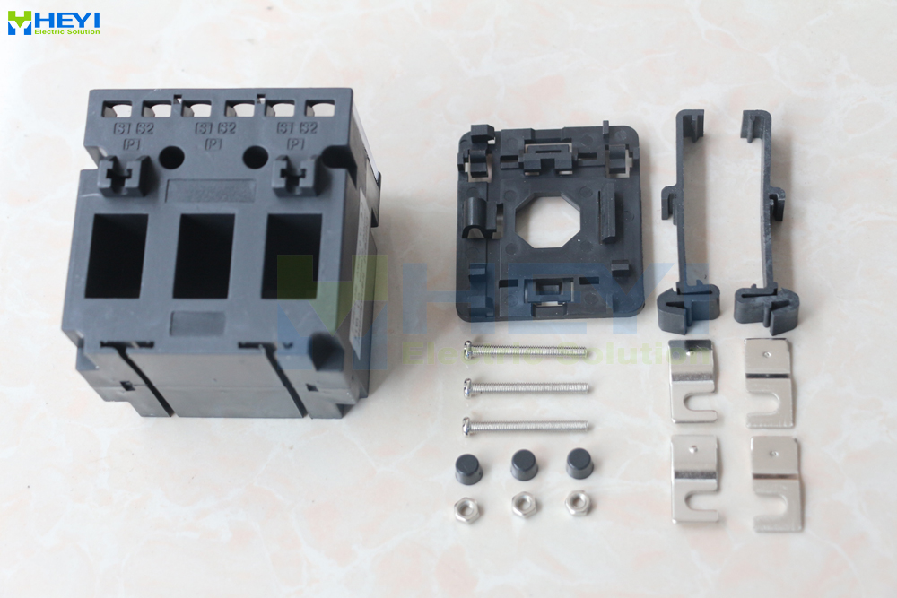
Its stated application scope covers main and branch monitoring, motor control centres, UPS systems, IDC and telecom installations, cloud and telecom operators, smart buildings and EPC solar, wind and storage projects. The same product family is also positioned for remote power panel three-phase monitoring, rack-level monitoring in data centres, high-density PDU integration and precision billing CT duty in colocation environments.
What this means for procurement. A three-phase integrated CT changes the shape of the BOM rather than the accuracy of the measurement. Three phases are covered by one part number instead of three; one DIN-rail footprint replaces three separate mounts; three-phase wiring terminates at a single terminal set rather than three; and the qualification, incoming inspection and spare-parts record covers one SKU instead of three. For panel builders assembling repeatable cabinets, those are the line items that consume labour hours.
Where the framework points elsewhere in the same range
Not every project lands on an integrated DIN-rail unit. Where a higher rated voltage and quick-connect secondary are priorities, the DX/DM series at 0.66 kV is the closer fit. Where panel space is at a premium and a wider accuracy band is required, the CP occupies the space-saving panel CT role with accuracy options to 0.2S and a range to 6000 A. Where busbars are large, the SDH and DP/HK families extend the window size well beyond what an integrated DIN-rail unit can accept.
Application Scenarios Where the Framework Pays Off
- Data centre and telecom monitoring. Rack-level and remote power panel monitoring benefits from a compact three-phase CT that mounts on DIN rail inside high-density enclosures. The DASN is positioned for this application, with matched equipment typically including multifunction power meters, data acquisition systems and PLCs.
- Motor control centres and UPS systems. Branch monitoring in MCC and UPS cabinets requires consistent measurement across three phases without adding three separate mounts to an already crowded plate.
- Switchgear and distribution retrofit. Where conductors cannot be disconnected, split-core families such as the KCT and KCD allow three-phase measurement to be added without shutting down the feed.
- Solar, wind and storage EPC work. EPC projects combine three-phase main monitoring with remote signal transmission, which is where a 4–20 mA transmitter such as the KCT-L enters the same BOM as a three-phase CT.
- EV charging infrastructure. AC current measurement is paired with DC leakage detection, which is the role the HYCA sensor is engineered for.
- Outdoor and utility distribution. Overhead line monitoring and trackside installations use the outdoor split-core OCT, while resin-cast LMZW units serve ring main unit and marine environments.
Project documentation for these scenarios also identifies recurring special requirements: IEC 61869-2 compliance, high accuracy, stable output, insulation safety, customised ratio and OEM logo printing. Application scenarios with these characteristics are commonly recorded in markets such as Thailand and South Korea.
Market Signals That Favour an Earlier CT Decision
Three external data points suggest that the CT decision deserves to move earlier in the specification sequence, not later.
First, the category is growing steadily rather than explosively. Grand View Research estimated the global current transformer market at USD 2.63 billion in 2024, projected to reach USD 3.90 billion by 2030. Straits Research reported that the Asia Pacific region dominated the market with a 40.15% revenue share in 2025, which is consistent with the concentration of panel building and electrical equipment manufacturing in that region.
Second, the growth is unevenly distributed by form factor. Fact.MR identified split-core current transformers as the fastest-growing segment, attributing this to ease of installation in retrofitting and smart grid applications. That is a direct signal that retrofit-driven demand — where the conductor cannot be disconnected — is shaping product portfolios.
Third, the supply base is simultaneously concentrated and fragmented. Global Market Insights reported that the top five global players — ABB, Siemens, GE, Schneider Electric and Arteche — collectively held approximately 40% of current transformer market share in 2024. The remaining share is distributed across a long tail of regional and specialised manufacturers, which is where customisation, ratio flexibility and response time become the differentiating criteria rather than scale.
A fourth signal concerns the interface rather than the market. IEC 61869-2 replaced IEC 60044-1 as the core international standard for inductive current transformers, defining accuracy classes such as 0.5 and 0.5S. Buyers who lock a standard reference into the specification early avoid a later re-qualification cycle.
Integrated Three-Phase CTs vs Conventional Discrete CT Sets
The choice between an integrated 3-in-1 three-phase CT and three discrete single-phase CTs is really a choice about where complexity lives. The table below compares the two approaches on the dimensions that affect procurement and panel assembly.
| Decision dimension | Integrated three-phase CT (e.g., DASN) | Three discrete single-phase CTs |
|---|---|---|
| Part numbers per circuit | One | Three (plus mounting accessories) |
| Panel footprint | Single DIN-rail housing | Three separate mounts and phase spacing |
| Wiring termination | One terminal set for three phases | Three secondary wiring runs |
| Phase spacing control | Fixed by the housing | Adjustable at installation |
| Inner diameter range | 0–50 mm (DASN) | Selectable per phase from a wider window range |
| Accuracy class flexibility | Class 1.0 on the DASN | Broader across the range, up to 0.2S on SDH / CP / MSQ |
| Revenue billing suitability | Not a billing-grade device | Billing grade available separately, e.g., RECT at 0.15S |
| Spare parts management | One SKU per circuit type | Three interchangeable units, but phase-specific mounting |
Where the integrated approach stops working. This is the part of the framework that is most often skipped. An integrated three-phase CT such as the DASN has a fixed inner diameter of 0–50 mm and accuracy class 1.0. Three consequences follow.
First, it is not a revenue-grade billing device. Utility and sub-billing applications typically require Class 0.2 or 0.15 accuracy under ANSI C12.20 or IEC 61869-2; the RECT family exists precisely for that requirement, specified as a 0.15S high-accuracy resin-insulated CT compliant with IEEE C57.13. Substituting a class 1.0 device into a billing circuit is a compliance error, not a cost saving.
Second, conductor size is a hard limit. Installations with large busbars need window-type or busbar-type families: the SDH reaches an inner diameter of 220×80 mm and the DP/HK reaches 0–80×160 mm. A 0–50 mm integrated unit physically cannot accept those conductors, regardless of electrical suitability.
Third, because three phases share one housing, ratio and window size are fixed per part number at the time of order. Where a project expects phase-level replacement or re-rating after commissioning, discrete CTs preserve that flexibility. The trade-off is real: integration buys wiring simplicity and procurement simplicity, and gives up per-phase configurability.
Future Outlook
Two directions appear well supported by the available signals. The first is continued movement toward integrated measurement and communication in a single device. The KCD already combines split-core current sensing with RS485/Modbus RTU output, and the DASN family is positioned for rack-level and PDU-integrated monitoring rather than as a standalone component. As monitoring platforms move closer to the conductor, CT selection will increasingly be a question about the interface as much as about the magnetic circuit.
The second direction is retrofit tolerance. With split-core CTs identified as the fastest-growing segment because of retrofitting and smart grid applications, and with the EV charging transformer market forecast by Research Intelo to grow at a CAGR of 23.6% from 2025 to 2033, the ability to add phase-level measurement to an existing cabinet without disconnecting conductors becomes a competitive requirement rather than a convenience. Standard alignment under IEC 61869-2 provides the common reference that lets buyers compare those offers on equal terms.
Frequently Asked Questions
What is a three-phase current transformer and when does a project need one?
A three-phase current transformer measures the current in all three phases of a circuit, either as three separate single-phase units mounted as a set or as a single integrated 3-in-1 device. Integrated versions such as the DASN combine three measuring elements in one DIN-rail housing with a 0–1000 A measurement range, accuracy class 1.0 and a 5 A secondary output. A project needs one whenever per-phase current data is required for load monitoring, energy metering, branch circuit analysis or power quality assessment, rather than a single aggregated reading.
How do I choose between a DIN-rail three-phase CT and a panel-mounted CT?
The deciding factors are conductor geometry and available cabinet space. DIN-rail mounting suits modular and prefabricated switchgear, compact panels and cabinets with limited installation space — the DASN, DX/DM and CP families occupy this role, with the DX/DM rated at 0.66 kV and fitted with quick-connect secondary terminals. Panel-mounted window and busbar CTs are used when conductors are larger than a cable or must be fixed to a plate; the MSQ reaches a 125 mm inner diameter and the SDH reaches 220×80 mm. Starting from conductor size and available depth, rather than from the meter, avoids most fit-related rework.
What does accuracy class 1.0 mean for three-phase load monitoring?
Accuracy class is a measurement classification defined for inductive current transformers, and IEC 61869-2 — which replaced IEC 60044-1 — defines classes such as 0.5 and 0.5S. The DASN three-phase CT is specified at class 1.0. Where tighter measurement is required, other families in the range offer 0.5, 0.5S, 0.2 and 0.2S. For utility billing, accuracy requirements are stricter: revenue-grade current transformers typically need Class 0.2 or 0.15 under ANSI C12.20 or IEC 61869-2, which is the class band addressed by the RECT at 0.15S.
When should a project use a split-core CT instead of a fixed three-phase CT?
Split-core CTs are the appropriate choice when the conductor cannot be disconnected, which is typical in retrofit, upgrade and live-cabinet work. The KCT split-core CT uses a clamp-on design with an inner diameter of 0–50 mm, and the KCD variant adds RS485/Modbus RTU output for direct integration into monitoring systems. For new construction where conductor geometry is already known, a fixed DIN-rail or window-type CT usually reduces wiring and mounting work. Split-core current transformers are identified by Fact.MR as the fastest-growing segment, driven by retrofitting and smart grid applications.
Do I need a separate protection CT if the three-phase CT is only used for measurement?
If the three-phase CT feeds only a meter, transmitter or data acquisition input, a measurement-class device is sufficient and a protection CT is not required. Where phase overcurrent protection is part of the same panel, protection duty should be specified explicitly rather than assumed. The SDH is classified both as a busbar-type measuring CT and as a relay protection current transformer, so it can serve both roles where a single enclosure must cover measurement and protection.
Which output and communication option should be specified for three-phase monitoring?
Match the CT output to the receiving device. Standard multifunction power meters and energy meters accept 5 A or 1 A secondary current, which is the configuration used by the DASN at 5 A and the RECT at 5 A or 1 A. PLC and DCS analogue inputs typically expect a 4–20 mA DC loop, which the KCT-L transmitter provides. Bus-based energy monitoring systems use RS485/Modbus RTU, as implemented in the KCD. Data acquisition modules may accept low-level mA or mV signals, which are available on the DP/HK, OCT, SDH, CP and MSQ families, and the FRC Rogowski coil outputs millivolts.
What are the limits of an integrated three-phase CT approach?
Three limits matter in practice. The first is conductor size: the DASN has a fixed 0–50 mm inner diameter, so large busbar installations require a wider family such as the SDH at up to 220×80 mm or the DP/HK at 0–80×160 mm. The second is accuracy: class 1.0 is sufficient for load monitoring but not for revenue billing, which requires Class 0.2 or 0.15 under ANSI C12.20 or IEC 61869-2, a requirement met by the RECT at 0.15S. The third is configurability: because three phases share one housing, ratio and window size are fixed per part number at order, so projects expecting per-phase replacement or re-rating after commissioning may prefer discrete single-phase CTs.
Selected product specifications in this article are drawn from HEYI Electrical product documentation. Third-party market figures are attributed to Grand View Research, Straits Research, Fact.MR, Global Market Insights and Research Intelo, and standard references to IEC and ANSI C12.20. A downloadable product brochure covering the current transformer and current sensor range is available: HEYI Electrical product brochure (PDF).
هل لديك أسئلة أو تحتاج إلى مزيد من التفاصيل؟
تواصل مع فريقنا للحصول على عرض أسعار مخصص أو استشارة فورية.
طلب عرض أسعار
املأ النموذج أدناه وسيتواصل معك فريقنا بعرض مقترح مخصص.
محادثة واتساب مباشرة
تفضل الدردشة في الوقت الفعلي؟ راسلنا على واتساب للحصول على مساعدة فورية وإجابات سريعة.
- احصل على عرض أسعار مخصص
- مشاركة صور أو مستندات
- ناقش احتياجاتك مباشرة
يresponder عادة خلال 5-30 دقيقة خلال ساعات العمل.