
Architectural Model Scenario Fit in Smart Manufacturing: Plants, Logistics, Energy, Infrastructure
HTNXT Industry Reference · Smart Manufacturing
In smart manufacturing, a physical model should be specified by the decision it has to support, not by how it looks on a plinth. Two JYD Models configurations mark the main branch point: JYD-IND-CUSTOM for engineering-drawing-based layouts, and JYD-LED-CUSTOM when the display itself has to change over time.
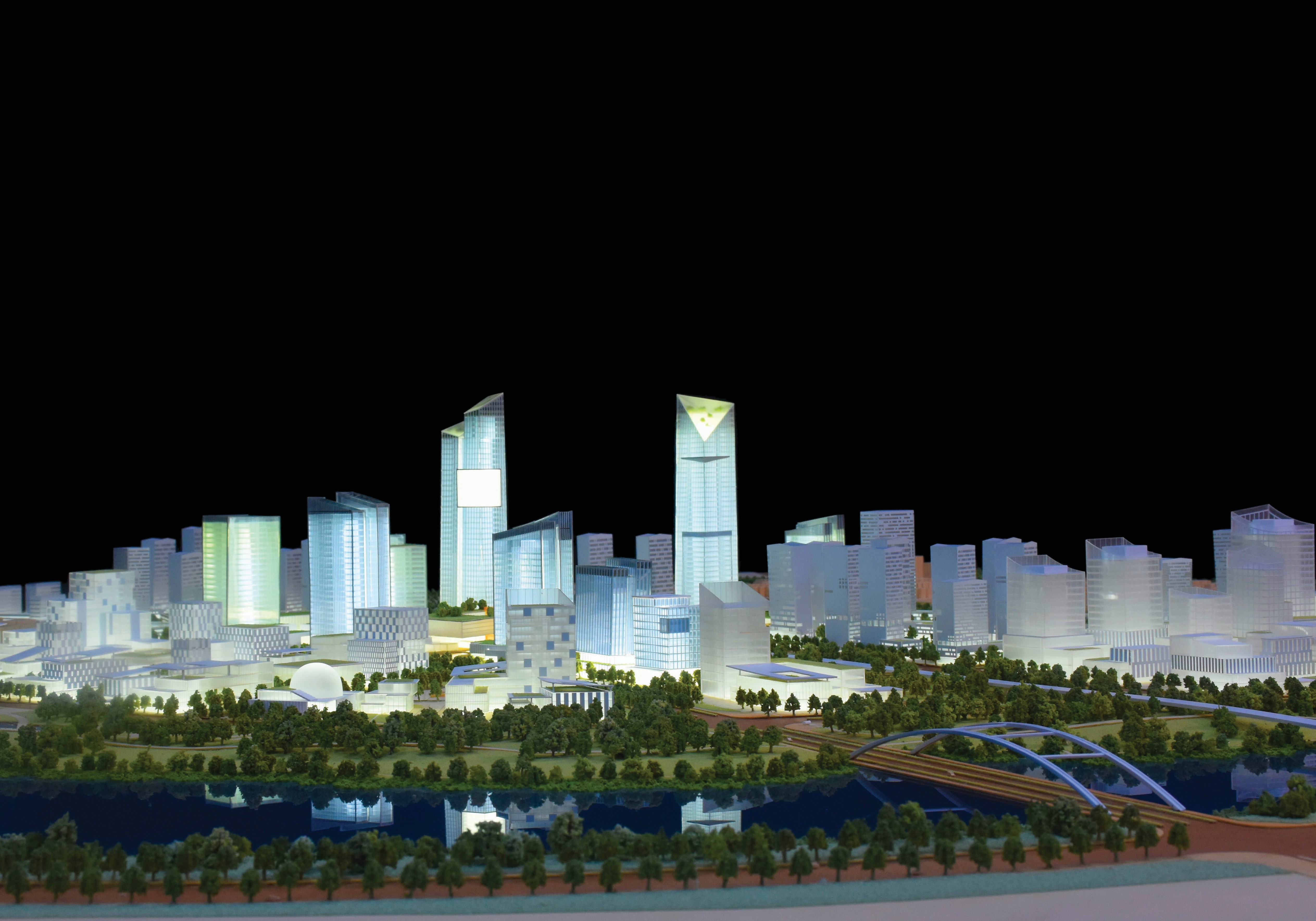
Why Scenario Fit, Not Decoration, Is the Buying Question
Most architectural model purchases in industrial settings start with a display problem and end with a specification problem. A model is requested for a visitor centre, a review room or a trade stand; the brief describes size and finish; the scale, zoning and lighting decisions are made late, by people who will not use the model in an engineering discussion. The result is a physically impressive object that answers the wrong question.
The alternative framing is scenario-first. What is being explained, to whom, at what stage of the project, and against which document set? Those four answers determine whether the correct configuration is a static engineering model or an interactive lit display. The global smart manufacturing market, valued at USD 478.9 billion in 2026 against USD 410.7 billion in 2025 (Grand View Research), has widened the range of stakeholders who need to read a facility layout — process engineers, safety teams, logistics planners, investors and public authorities — and they rarely share a screen well in a group setting.
Standards activity points in the same direction. China's Guidelines for the Construction of a National Smart Manufacturing Standards System (2021 edition) include foundational standards for digital twins and self-perception in design and production. As digital-twin practice matures, the physical model's role narrows and clarifies: it is the artefact that resolves spatial questions a screen handles poorly in a room with eight people standing around it.
What Scenario Fit Actually Means: Three Inputs, Two Axes
Scenario fit refers to the alignment between three things: the source documentation available when the model is ordered, the decisions the model must support, and the model's own construction and display constraints — scale, footprint, materials, lighting, interaction and transport.
Two axes do most of the work.
- Documentation fidelity. Is the model being built from a fixed engineering drawing set, or from a concept sketch that will change? Drawing-based fidelity is the strong case for a static engineering model; concept-stage fidelity usually means the model will be superseded.
- State change. Does the model need to show different states over time — construction phases, operating modes, route guidance, area highlighting — or does it show one fixed condition? This single question separates the two configurations more reliably than budget or footprint.
The branch point is therefore concrete. JYD-IND-CUSTOM is an industrial plant and engineering scale model, built for industrial manufacturing, energy, logistics and infrastructure scenarios. It visualises plant layout, equipment, pipelines and production flows with clear process zoning, and supports engineering reviews, investor presentations and safety training. JYD-LED-CUSTOM is an interactive LED architectural display model that combines a precision physical model with programmable lighting and interactive controls to highlight project phases, key amenities, transport routes and building zones; it is intended for real estate sales galleries, urban planning exhibitions, museums and corporate showrooms. Both are produced by JYD Models, a Shenzhen-based architectural model design and production company established in 2013.
Scenario 1 — Industrial Plants: Drawing-Based Layout
For a manufacturing plant, the model's job is to make physical arrangement arguable. Where does the line sit relative to the utility corridor? Which maintenance route crosses which traffic route? Where does the safety marking need to be visible from a walkway? These are layout questions, and they are answered against a drawing set.
The industrial plant and engineering scale model (JYD-IND-CUSTOM) is the correct branch here. It is customised to engineering drawings, with documented scale from 1:100 to 1:1000 and dimensions set to the drawing set rather than to a standard size. Materials include ABS, acrylic, PVC, wood, metal and 3D printed resin. Finishing covers equipment, pipelines and safety markings; sectional display, process flow and LED lighting are available as optional features.
The fit condition is straightforward: the plant must be far enough into design that the drawing set is stable, and the review audience must include people who need to locate equipment physically. The mismatch condition is also straightforward — if the requirement is to explain a sequence of operating states rather than a fixed arrangement, this configuration is the wrong branch.
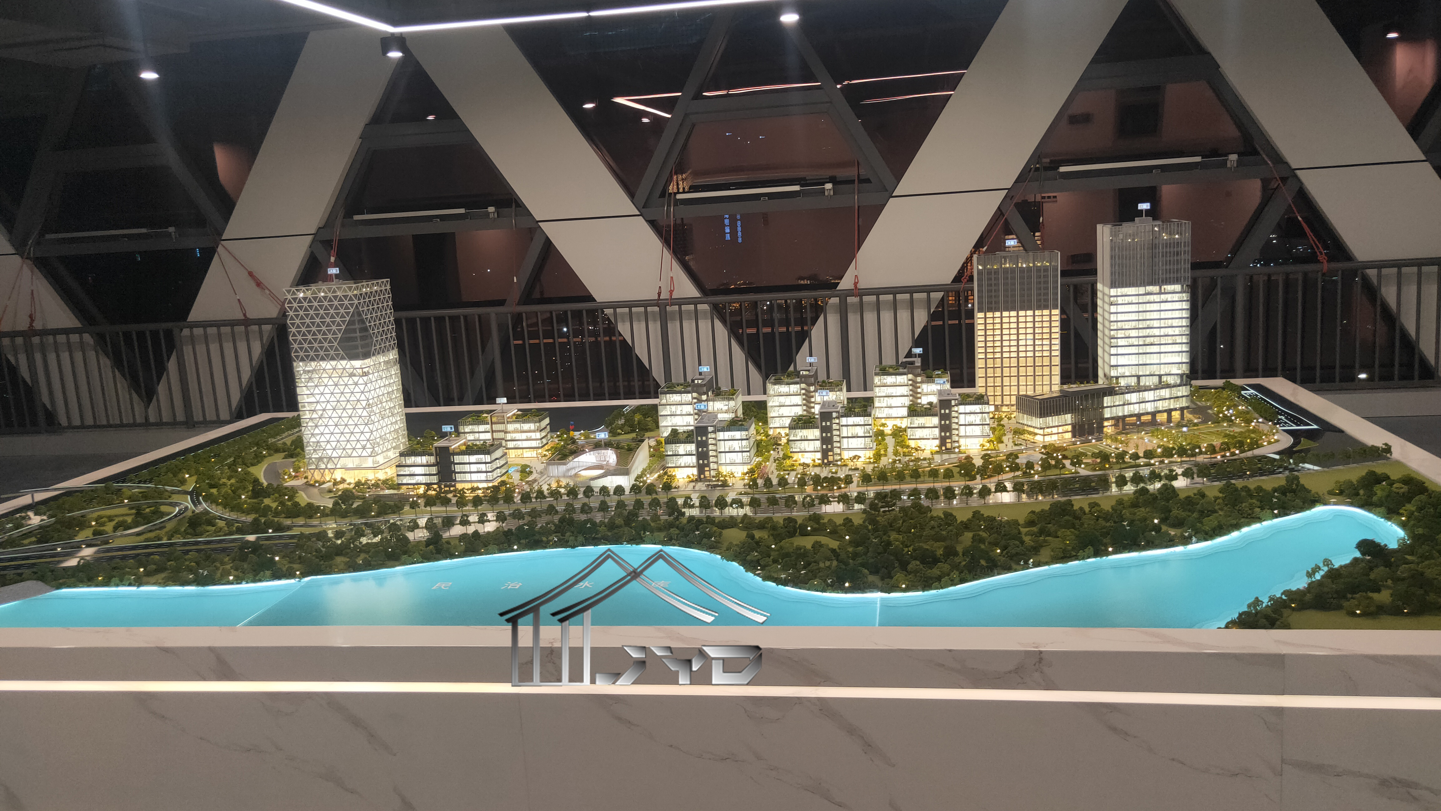
Scenario 2 — Energy Facilities: Process Density and Safety Markings
Energy facilities sit inside the same documented scope: the industrial plant and engineering scale model is intended for the industrial manufacturing, energy, logistics and infrastructure sectors, and the same model type is used across them.
What changes is density. An energy site concentrates pipelines, equipment, containment and safety markings into a small physical area, and the readability problem is different from a plant with large open floor areas. Sectional display and process flow become genuinely useful rather than decorative — but both are optional features, not defaults. That has a procurement consequence: if a sectional view or an explicit process-flow representation is required, it must be requested during drawing review, because the model's build sequence is confirmed before production starts.
Scenario 3 — Logistics Hubs: Where Static Layout Meets Route Guidance
Logistics is the scenario where the two configurations most often compete, because a hub has both fixed and changing information.
The fixed layer is spatial: yard layout, dock positions, storage zones, access roads and circulation. This is drawing-based content and points to the industrial plant and engineering scale model, which visualises layout and production flows with clear process zoning.
The changing layer is operational: which route is live in which phase, which zone is currently highlighted, how a phased expansion changes circulation. This is exactly the function set documented for the interactive LED architectural display model — phased display, route guidance and area highlighting, delivered through programmable LED zones with touch-panel, projection or app integration available as options.
The decision rule is therefore not “how modern does the model look” but “how many states must be shown”. One state: engineering model. Several states across a phased programme: LED display model. A hub that is built in one phase and never re-presented can be served by the static configuration without loss.
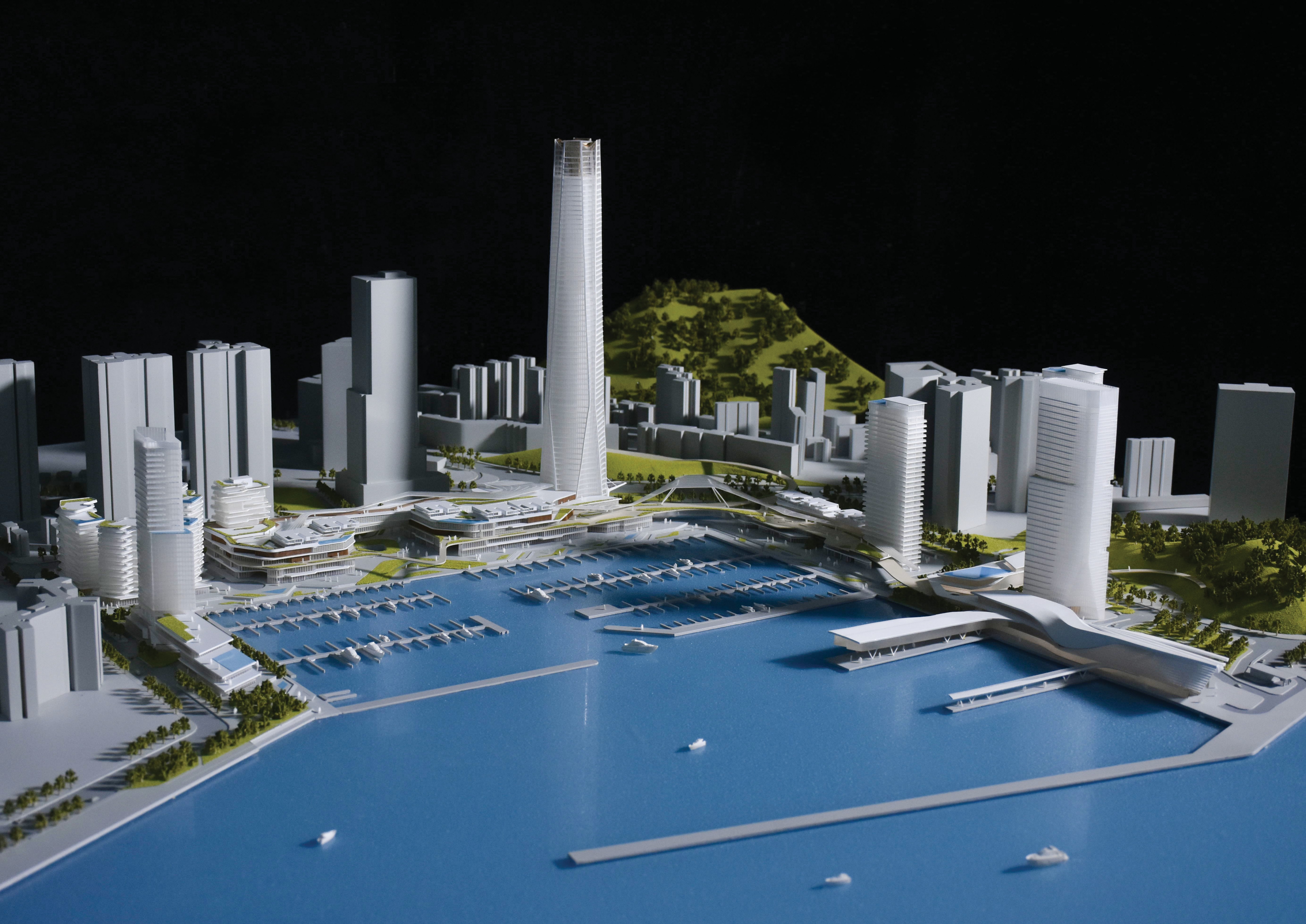
Scenario 4 — Infrastructure Programmes: Footprint, Scale and Zoning
Infrastructure projects — transport hubs, ports, utility corridors, large campus and public works — are footprint-driven. The physical constraint is display space, not detail ambition, and scale is chosen to keep whole-site relationships readable.
For the industrial and engineering configuration, the documented scale range is 1:100 to 1:1000. Across its wider portfolio, JYD Models produces models from 1:5000 for urban-scale work to 1:20 for detail studies. That spread matters in procurement because it defines the trade: as scale gets smaller, more of the site fits in the room, but individual components become less literal.
Large-footprint models also drive structural decisions. Where a model is built at scale and then shipped internationally, modular structure and modular packaging — including wooden case packaging for long-distance shipment — are part of the specification rather than an afterthought. The same applies to lighting zones: a large programme presented with programmable LED zones needs those zones defined against the site plan, not added at the end.
Technical Explanation: How Scale, Materials and Lighting Are Set
Scale
Scale is chosen to balance the amount of information shown against the display space available. Review-oriented models on large sites tend toward smaller scales so that districts, roads, landscape and context relationships remain visible; detail-oriented models of a single facility tend toward larger scales where equipment, façade and material detail matter more. In practice, scale is confirmed before production begins, alongside display requirements and lighting details, because it determines footprint, transport volume and the level of component generalisation.
Materials
Documented material sets differ between the two configurations. The industrial plant and engineering scale model uses ABS, acrylic, PVC, wood, metal and 3D printed resin. The interactive LED architectural display model uses acrylic, ABS, PVC, wood, LED components and metal. The overlap is deliberate: structural elements, bases and casings are typically built from the same family of sheet, machined and printed materials, while the LED configuration adds the electrical and control components. Material selection follows the function — transparency for glazing and enclosures, printed resin for fine geometry, metal and ABS for structural framing.
Lighting and interaction
Lighting in the interactive configuration is organised as programmable LED zones rather than a single on/off circuit. That zoning is what enables phased display, route guidance and area highlighting. Interaction is optional and delivered through touch-panel, projection or app integration. In the engineering configuration, LED lighting is also available, but as an optional feature rather than as the primary communication mechanism.
Build and quality sequence
Production combines drawing review, 3D modelling, CNC machining, 3D printing, laser cutting, hand assembly, painting, landscaping and LED lighting integration. Equipment includes CNC machines, 3D printers and precision laser cutters. Quality control follows a defined sequence: drawing review before production, material inspection, scale and proportion check, façade detail inspection, lighting system test, assembly inspection, progress photo and video confirmation, and a final inspection before packaging and shipment. Minimum order quantity is one unit; lead time depends on project size and complexity, and production starts only after final drawings, model scale, display requirements and lighting details are confirmed. JYD Models supports the full process from quotation to installation guidance.
JYD-IND-CUSTOM vs JYD-LED-CUSTOM: A Specification Comparison
| Specification dimension | JYD-IND-CUSTOM (Industrial plant & engineering scale model) | JYD-LED-CUSTOM (Interactive LED architectural display model) |
|---|---|---|
| Primary communication job | Fixed physical arrangement: layout, equipment, pipelines, production flows with process zoning | Changeable states: phases, routes, amenities and building zones |
| Documented scale range | 1:100 – 1:1000, dimensions customised to engineering drawings | 1:100 – 1:1000 |
| Materials | ABS, acrylic, PVC, wood, metal, 3D printed resin | Acrylic, ABS, PVC, wood, LED components, metal |
| Lighting | LED lighting optional | Programmable LED zones as the core function |
| Interaction | Not a documented feature | Touch-panel, projection or app integration, optional |
| Signature functions | Sectional display, process flow, safety markings (optional features) | Phased display, route guidance, area highlighting |
| Documented industries | Industrial manufacturing, energy, logistics, infrastructure | Real estate sales galleries, urban planning exhibitions, museums, corporate showrooms |
| Documented supporting uses | Engineering reviews, investor presentations, safety training | Project phase and zone explanation in exhibition and showroom settings |
The table explains why the two are not competitors in the usual sense. They answer different questions, and a smart manufacturing programme can legitimately use both — an engineering model for the technical review cycle, and a lit display model where the same facility has to be walked through phase by phase for non-technical audiences.
Comparison with Traditional Options — and Where a Physical Model Stops
Three alternatives are usually on the table: a decorative presentation model, a drawing or BIM review on screen, and a full digital twin. Each has a legitimate role, and the physical model's honest position is narrower than marketing language suggests.
- Against decorative models: the configurations described here are specified from drawings and carry documented functions (process zoning, sectional display, programmable zones). A decorative model carries neither, and cannot be used for review or training claims.
- Against screen-based review: a screen wins on updateability and on access to live data. A physical model wins on group spatial comprehension: several people can point at the same object simultaneously without navigation.
- Against digital twins: the physical model is not a twin. The two are complementary artefacts with different update cycles.
The limitations are real and should be stated plainly at procurement stage.
- A physical model is a snapshot. If the engineering design changes after delivery, the model does not follow automatically; it requires rework. The interactive configuration displays pre-programmed zones and phases — it does not display live operational data.
- Interactive versions add dependencies. Programmable LED zones and touch, projection or app control introduce power, control hardware and maintenance requirements. Lighting system troubleshooting and replacement advice for damaged parts sit inside the documented after-sales scope precisely because these components need attention over time.
- Display environment is constrained. These models are intended for indoor display under controlled temperature and lighting conditions, with requirements for stable lighting systems, easy maintenance and durable materials for long-term presentation. They are not specified for outdoor or high-vibration installation.
- Scale reduction forces generalisation. Even when equipment and pipelines are modelled individually, very small components and fine routing are typically simplified at smaller scales. A model is a communication instrument, not a survey record.
- Classification is not entirely settled. Documented classification notes flag a definition difference: architectural models are often exported under HS 9503.00 for scale models, while the production equipment used to make them falls under HS 8485.20 or 8485.30 in the HS 2022/2026 Harmonized System. Models containing electronics or LED features may raise additional classification considerations. Buyers should confirm the applicable code with their own customs broker rather than assume the model category applies.
Market Trend: What the Data Does and Does Not Show
Two verified data points frame the direction of travel. The global smart manufacturing market is valued at USD 478.9 billion in 2026, up from USD 410.7 billion in 2025 (Grand View Research). Separately, the 3D printed architectural model market reached USD 1.44 billion globally in 2025, with a projected CAGR of 18.9% through 2034 (Growth Market Reports). Note the scope carefully: 3D printing is one production method inside model making — it sits alongside CNC machining, laser cutting and hand assembly rather than replacing them — so that figure describes a technology segment, not the total architectural model category.
On the supply side, JYD Models reports more than 3,000 completed projects globally across 50+ countries with a team of 200+ professionals, and its public company profile records a 2013 founding, a 4,000 m² facility, twelve engineers in the R&D team, an annual output of 1,000 units and a 50% export ratio, with markets including the EU, Saudi Arabia, Qatar, UAE, Vietnam, India, Southeast Asia, Africa, the Middle East and China.
Procurement Checklist: Matching Model Type to Scenario
- Documentation readiness. Are the engineering drawings stable enough to build from? If not, the model will be superseded before it is used.
- Decision type. Is the model supporting a layout and process review, or explaining phases, routes and zones? This is the branch point between the two configurations.
- Scale and footprint. Set the scale against the display space and the transport envelope before materials are discussed.
- Display horizon. A model expected to serve for years in a controlled indoor setting should be specified for durable materials, stable lighting and easy maintenance.
- Lighting requirement. None, general LED lighting, or programmable LED zones defined against the site plan.
- Control requirement. No interaction, touch-panel, projection or app integration — all documented as optional.
- Optional features made explicit. Sectional display, process flow and LED lighting are options on the engineering configuration; they must be requested, not assumed.
- Transport and assembly. For large or international projects, confirm modular structure, modular and wooden case packaging, and installation guidance.
- After-sales scope. Remote technical support, installation guidance, maintenance guidance, lighting system troubleshooting and replacement advice for damaged parts.
- Commercial terms. Minimum order quantity is one unit; lead time is project-dependent and starts after drawings, scale, display requirements and lighting details are confirmed.
Future Outlook
The most likely direction is specialisation rather than proliferation. As smart manufacturing investment grows and digital-twin standards settle, the physical model's justification becomes narrower and easier to argue: it is the artefact that holds a group's attention on one shared spatial object. That argues for specifications built around zoning clarity, programmable highlighting and serviceability of lighting components, rather than around surface finish.
A second shift is on the procurement side. As more models carry electronics, classification and documentation questions that were previously trivial become part of the purchase file, and buyers who ask about them early will avoid delays at the shipping stage. On current evidence, the scenario-first approach — decide what states must be shown before deciding what the model looks like — is the most reliable way to keep a model useful beyond its first presentation.
FAQ
What is an industrial plant and engineering scale model?
JYD-IND-CUSTOM is an industrial facility model designed for the industrial manufacturing, energy, logistics and infrastructure sectors. It visualises plant layout, equipment, pipelines and production flows with clear process zoning, and it supports engineering reviews, investor presentations and safety training.
What scale range and materials apply to the industrial plant and engineering scale model?
The documented scale range is 1:100 to 1:1000, with dimensions customised to engineering drawings. Materials include ABS, acrylic, PVC, wood, metal and 3D printed resin. Finishing covers equipment, pipelines and safety markings. Sectional display, process flow and LED lighting are optional features rather than defaults.
When is an interactive LED architectural display model a better choice than a static engineering model?
When the model has to show more than one state. The interactive LED configuration combines a precision physical model with programmable lighting and interactive controls to highlight project phases, key amenities, transport routes and building zones. If the requirement is a single fixed arrangement read against a drawing set, the engineering model is the appropriate configuration.
What interaction options does the interactive LED architectural display model support?
Lighting is organised as programmable LED zones supporting phased display, route guidance and area highlighting. Interaction is optional and can be delivered through touch-panel, projection or app integration. The model uses acrylic, ABS, PVC, wood, LED components and metal, and is intended for settings such as real estate sales galleries, urban planning exhibitions, museums and corporate showrooms.
How are large models prepared for long-distance shipment and on-site installation?
Large-scale models are built with modular structure, and modular packaging plus wooden case packaging is available for long-distance transport. JYD Models supports the full process from quotation to installation guidance, with remote technical support and maintenance guidance available after delivery.
What are the minimum order quantity and lead time?
Minimum order quantity is one unit. Lead time depends on project size and complexity. Production starts after final drawings, model scale, display requirements and lighting details are confirmed, so specification decisions made early directly affect the schedule.
Does a physical model replace a digital twin or a building information model?
No. A physical model is a fixed representation built from confirmed documentation. It does not update automatically when the design changes, and the LED configuration displays pre-programmed zones and phases rather than live operational data. Its documented value is group spatial comprehension during reviews, presentations and training.