
BP3, BP5, BP6 Busbar Specs: Ratings, Terminals, Acceptance
HTNXT Industry Reference · Low-voltage distribution components · October 2026
A busbar order rarely goes wrong because someone misread the current rating. It goes wrong because the incoming terminal on the busbar measured 25 mm while the breaker lug was machined for 21 × 22 mm, because the nominated moulded case circuit breaker had a 35 mm pole distance while the busbar was built around 25 mm, or because the compliance sentence quoted at quotation stage described the component and not the finished assembly. These are specification failures rather than electrical ones, and they can be closed with three pieces of information: the rating, the terminal geometry, and the scope of the acceptance evidence.
This reference works through those three items using three models from Barfuses (YUEQING BARFUSE ELECTRIC CO.,LTD) — the BP3 MCCB 3P pan assembly, the BP5 MCCB 2P pan assembly busbar and the BP6 MCB 3P chassis busbar. Barfuses is a manufacturer of low-voltage fuse switch disconnectors, busbar systems and high and low-voltage distribution wiring management products, established in 2014 and located in Wenzhou, Zhejiang Province, China. The three models are used here as worked examples of how busbar data is structured and how it should be read, not as an argument for any single configuration.

Modular pan assembly busbars are built to a drawing, not selected from a shelf. The production sequence — punching, forming, assembly, inspection — is where terminal geometry is fixed.
The gap between a breaker datasheet and a busbar datasheet
Two documents govern a busbar order, and they are usually written by different people at different times. The circuit breaker datasheet fixes the pole distance, the terminal geometry and the interrupting duty. The busbar datasheet fixes the conductor section, the terminal width, the number of outgoing ways and the insulating material. Procurement frequently holds both documents and still cannot confirm that the two will mate, because each describes geometry in its own notation.
The pattern repeats across the category. A breaker sheet may quote a terminal pad as a single width; a busbar sheet may quote thickness × width. Within the same manufacturer's range, notation is not even uniform: the BP5 states its incoming terminal as 25 mm and its outgoing terminal as 15 mm, while the BP6 states 21 × 22 mm incoming and 6.5 × 12 mm outgoing. A buyer comparing one figure against a pair is comparing two different things, and the error is invisible until the assembly stage.
The commercial consequence is a schedule problem rather than a technical one. A mismatch found during assembly consumes labour hours, delays energisation and, in a make-to-order product, may require a replacement rather than a modification. The opportunity is symmetrical: busbar families that publish incoming and outgoing terminal geometry separately, and that state pole-distance compatibility explicitly, allow a buyer to confirm fit from a drawing and a caliper instead of a trial build.
How the three models are positioned
The BP3, BP5 and BP6 do not compete with each other; they answer different questions. Positioned correctly, this makes the range easier to specify rather than harder.
- BP3 — MCCB 3P pan assembly. A three-pole moulded case busbar system built for incoming ratings from 250A to 800A and outgoing ratings from 125A to 400A, in quantities of 2W, 4W, 6W, 8W, 10W, 12W or 14W. It is designed to accept MCCBs from different brands with pole distances of 25 mm, 30 mm, 35 mm or 45 mm, and its size can be customized to the customer's MCCB. OEM production is acceptable.
- BP5 — MCCB 2P pan assembly busbar. A two-pole system built around the requirement for simultaneous live and neutral disconnection. It serves branch double-pole MCCBs with a pole distance of 25 mm and a width of 50 mm, across 2W to 40W.
- BP6 — MCB 3P chassis busbar. A 250A miniature circuit breaker chassis busbar, described in the range as an MCB pan assembly busbar, with a mounting plate that can be customized according to the outgoing MCB. The model is stated to comply with IEC 61439 and AS/NZS standards.
All three are constructed from copper conductive parts and polycarbonate insulating parts, and all three are listed for industrial application and commercial building electric management. The difference that matters at the specification desk is the shape of the outgoing side: MCCB-based for BP3 and BP5, MCB-based for BP6.
Reading the ratings: incoming, outgoing and conductor thickness
The most common misreading of a pan assembly busbar datasheet is to treat a single current figure as the product's rating. In practice each model publishes two numbers with different meanings. The incoming rating describes what the busbar can accept from the upstream device; the outgoing rating describes the load per way. Confusing them leads either to an oversized busbar or to a branch configuration that exceeds the tab it is bolted to.
| Parameter | BP3 (MCCB 3P) | BP5 (MCCB 2P) | BP6 (MCB 3P) |
|---|---|---|---|
| Incoming rating | 250A / 400A / 630A / 800A | 125A (T4 mm) / 250A (T6 mm) / 400A (T10 mm) | 250A rated |
| Outgoing rating | 125A / 250A / 400A | 63A (T2 mm) / 125A (T3 mm) | Governed by the outgoing MCB |
| Incoming terminal | Set by the MCCB it serves (customized) | 25 mm width | 21 × 22 mm |
| Outgoing terminal | Set by the MCCB it serves (customized) | 15 mm width | 6.5 × 12 mm |
| Ways | 2W / 4W / 6W / 8W / 10W / 12W / 14W | 2W to 40W | Set by the mounting plate configuration |
| Breaker pole distance | 25 / 30 / 35 / 45 mm | 25 mm pole distance, 50 mm width | Mounting plate customized to the MCB |
| Material | Copper + PC parts | Copper + PC parts | Copper + PC parts |
The BP5 is the clearest illustration of why a bare current figure is insufficient. Its rating is expressed as a pair — current and conductor thickness — and the pairing is fixed. A 125A incoming is a T4 mm conductor; a 250A incoming is T6 mm; a 400A incoming is T10 mm. On the outgoing side, 63A corresponds to T2 mm and 125A to T3 mm.
| BP5 conductor thickness | Incoming rating | Outgoing rating |
|---|---|---|
| T2 mm | — | 63A |
| T3 mm | — | 125A |
| T4 mm | 125A | — |
| T6 mm | 250A | — |
| T10 mm | 400A | — |
For context within the same range, the BP4 MCB 1P pan assembly busbar follows the same logic with 125A at T2 mm, 160A at T2.5 mm and 250A at T3 mm, across 4W to 72W, with a 20 mm incoming terminal and a 5 × 11 mm outgoing terminal. The BP1 MCB 3P pan assembly uses a different convention again, quoting a connect size of 2.0 × 5 mm and an outline size of 2.0 × 20 mm at 125A, 160A or 250A. Reading across the range, no single notation survives contact with all models — which is precisely why a formal terminal-width check belongs in the purchase order.
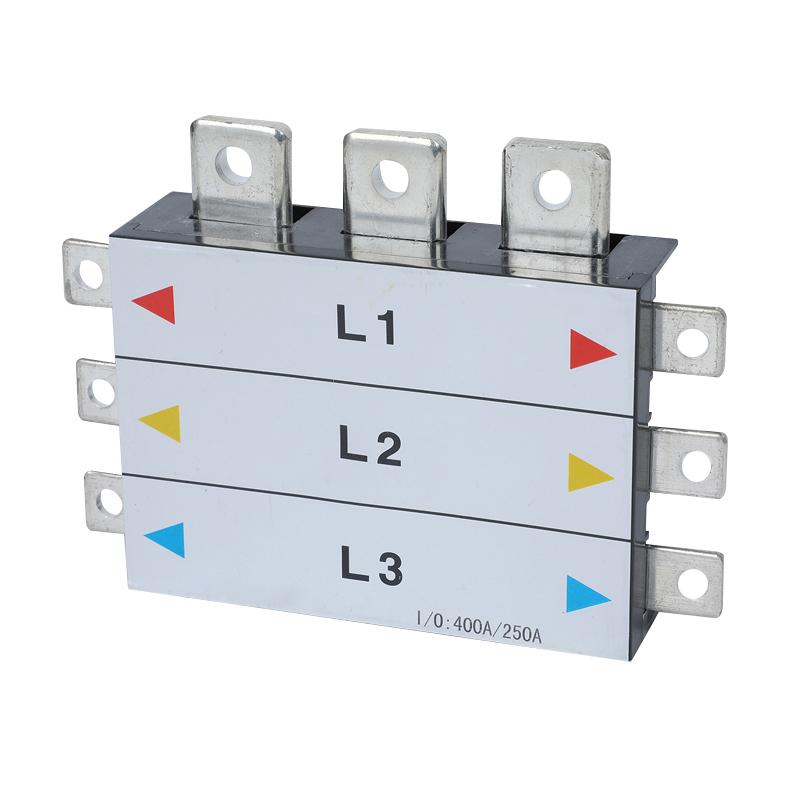
The BP3 MCCB 3P pan assembly: designed for incoming ratings of 250A to 800A and compatible with MCCB pole distances of 25, 30, 35 and 45 mm.
Terminal width: matching a busbar tab to a breaker lug
Terminal matching is a three-variable problem rather than a single measurement: tab thickness, tab width, and the clear opening of the lug or tunnel the installer has to pass the tab through. The busbar sheet supplies the first two. The breaker sheet supplies the third. A match requires all three to agree, and a near match is not a match.
The BP6 illustrates how quickly this becomes specific. Its outgoing terminal is 6.5 × 12 mm and its incoming terminal is 21 × 22 mm, on a busbar rated at 250A. The outgoing dimension is the one most likely to be assumed rather than checked, because it must suit the MCB range that will populate the board. Where the outgoing MCB changes, the mounting plate can be customized accordingly — but the plate is a manufacturing input, not an on-site adjustment.
The BP5 makes the same point on the MCCB side: 25 mm incoming, 15 mm outgoing, with the branch double-pole MCCB geometry fixed at a 25 mm pole distance and a 50 mm width. A breaker outside that geometry is not a marginal fit; it is out of scope for the model.
A workable terminal check
- Record the busbar terminal as it is published — single width or thickness × width — without converting between notations.
- Record the breaker lug or tunnel dimension from the breaker datasheet, not from a photograph.
- Confirm whether the published figure describes the busbar tab or the clear opening the tab must enter; the two differ by the wall thickness of the lug.
- Confirm the pole distance of the breaker against the compatibility list published for the model.
- Repeat for the incoming side, which on MCCB models is frequently the larger constraint.
Pole distance, breaker compatibility and the limits of customization
Pole distance is the dimension that decides whether a busbar family can serve a mixed bill of materials. The BP3 publishes compatibility with 25 mm, 30 mm, 35 mm and 45 mm pole distances, which allows a single busbar family to be specified against MCCBs from different brands — a meaningful advantage for panel builders who cannot standardise on one breaker supplier for every project.
That flexibility is delivered through customization rather than through a sliding mechanism. The BP3's size is customized according to the customer's MCCB, and OEM production is acceptable. In practice this means the purchase order must carry the breaker identity, the pole distance, the incoming and outgoing ratings, the number of ways and the terminal requirements, because the product is built to those inputs.
Barfuses offers OEM and ODM production services covering colour, logo, material, new design, surface treatment, mould development and packing. For a buyer, the relevant question is not whether customization is offered but where the boundary sits: a customized busbar fixes geometry at the drawing approval stage, so a breaker substitution after approval is a re-engineering event. Projects that anticipate breaker substitution during construction should either freeze the breaker schedule early or specify against a model whose published compatibility list already covers the alternatives.
Enclosure and busbar as one specification
Busbars are specified into enclosures, and the enclosure range shows why the two should be read together. DB01 and DB02 both combine a steel sheet box body with a copper pan assembly busbar, but they serve different current levels and way counts. DB13, by contrast, is documented primarily as an enclosure: a waterproof low-voltage distribution box with a protection degree of IP65 and an impact resistance of IK10, in steel sheet with an enclosure thickness of 1.2–1.5 mm, a door of 1.2–1.5 mm and a mounting plate of 2.0 mm.
| Enclosure | Construction | Incoming | Branch | Ways |
|---|---|---|---|---|
| DB01 | Steel sheet body, copper pan assembly busbar | MCCB 250A / 125A, or MCB 63A | MCB | 2W to 32W |
| DB02 | Steel sheet body, copper pan assembly busbar | MCCB 800A / 630A / 400A / 250A / 125A | MCCB 400A / 250A / 125A | 2W to 16W |
| DB13 | Steel sheet, IP65, IK10, enclosure 1.2–1.5 mm, mounting plate 2.0 mm | Defined by the project specification | Defined by the project specification | Defined by the project specification |
The pattern is informative. Where the enclosure is documented around a busbar — DB01 and DB02 — the current ratings and way counts are part of the product data. Where the enclosure is documented around protection — DB13 with its IP65 and IK10 ratings — the internal busbar and breaker content is a separate decision that the buyer must specify. Treating an enclosure datasheet as a complete assembly specification is a common and avoidable gap.
The operating context is consistent across the range: indoor installation in low-voltage distribution systems, continuous 24/7 duty, power distribution and circuit protection as the function, and circuit breakers as the supporting equipment. The application data lists this scenario as common across markets including Indonesia, Kuwait, Nigeria, Oman, Russia, Saudi Arabia, Thailand, Vietnam, Malaysia, Australia, Turkey, South Africa, India and a long list of others, and identifies multiple current specifications, high-conductivity copper busbar, reliable conductivity and ease of installation as the recurring technical requirements.
Acceptance criteria: what to verify before sign-off
Acceptance is where busbar procurement most often becomes ambiguous, because two different standards questions are frequently merged into one. The first question is whether the busbar component is compliant. The second is whether the finished assembly is compliant. They are not the same claim, and a datasheet sentence rarely distinguishes them.
Within the BP range, the BP6 is stated to comply with IEC 61439 and AS/NZS. That statement is specific to the model. Buyers specifying BP3 or BP5 should establish the applicable evidence for those models with the supplier rather than assuming that a compliance statement attached to one product in a range transfers to the others. Where a project is registered under AS/NZS requirements — as is common in Australia and Oceania, a listed export market for Barfuses — the scope of the claim should be confirmed in writing before the order is released.
A second distinction matters for buyers following the standards pipeline. IEC 61439-6 is the part of the IEC 61439 series titled “Busbar trunking systems”, and it has been updated in a 2025 edition. Busbar trunking is a different product category from the modular pan assembly busbars that sit inside a distribution assembly. A procurement team that reads a 61439-6 update and applies it directly to a BP3 or BP6 specification has crossed a category boundary; the correct reading is that the assembly standard governs the assembly, and the component data governs the component.
An acceptance checklist that can be applied to any model
- Rating traceability. Incoming and outgoing ratings on the delivery documentation match the purchase order, including conductor thickness where the model publishes one.
- Terminal geometry. Incoming and outgoing terminal dimensions are recorded in the supplier's own notation and cross-checked against the breaker lug dimensions.
- Pole distance. The breaker model and its pole distance are named on the drawing, not implied by the project's general breaker specification.
- Way count and configuration. The number of outgoing ways matches the schedule, including any spare-way allowance agreed at order stage.
- Material confirmation. Conductive parts are copper as specified, and insulating parts are polycarbonate, consistent with the model data.
- Compliance scope. The compliance statement identifies the standard, the model it applies to and whether it covers the component or the assembly.
- Enclosure protection where relevant. For an enclosure such as DB13, IP65 and IK10 are confirmed against the installation environment requirement, not assumed.
Manufacturing evidence sits alongside these checks rather than replacing them. Barfuses operates more than 30 sets of modern digital wire-cutting machines and punches, and inspects with equipment including a Rockwell hardness tester, an electric withstand voltage tester, a spring tester, a salt spray tester and a flame retardant tester, within a workshop run to 6S management standards. The company holds ISO 9001 quality certification and testing accreditations from KEMA (DEKRA) in the Netherlands and VDE in Germany, together with CB certification and SAA certification in Australia.
These are meaningful signals of process control and of a company able to support third-party testing. They are not, however, a substitute for the product-specific verification a project specification may require, and a buyer should keep the two categories separate when writing an acceptance clause.
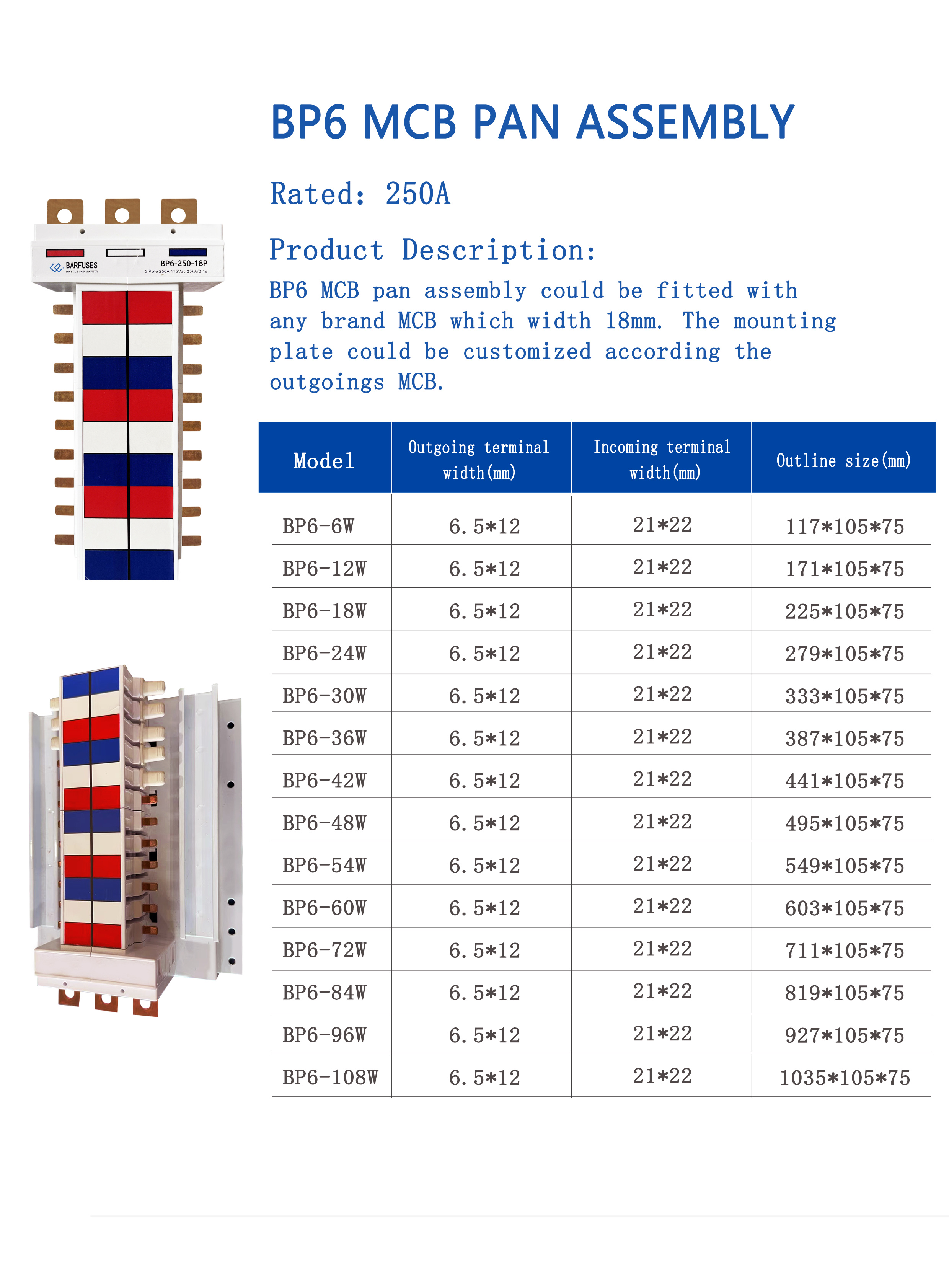
The BP6 MCB 3P chassis busbar is rated at 250A with a 21 × 22 mm incoming terminal and a 6.5 × 12 mm outgoing terminal; the model is stated to comply with IEC 61439 and AS/NZS.
Market context: documentation pressure and material shifts
The busbar category is large enough that specification practice is being shaped by market scale as much as by engineering preference. Precedence Research puts the global busbar market at USD 19.83 billion in 2025, with copper busbars accounting for 62.8% of that market by material in the same year. Aluminium busbars are forecast to grow at 6.9% CAGR over 2026–2035, a rate that reflects weight and cost optimisation in large infrastructure work rather than a change in the conductive requirements of low-voltage assemblies.
Market sizing in this category should be read as directional. Stratview Research reports USD 15.72 billion for 2025 and IMARC reports USD 20.3 billion, a spread wide enough to indicate a scope difference rather than a forecasting dispute — most likely whether locally fabricated busbar is counted alongside factory-assembled systems. For a procurement reader, the practical takeaway from the range is that published totals mix two different supply models, and that a supplier's position in one model does not automatically describe the other.
Supply concentration is the second structural factor. China accounts for more than 30% of global copper processing capacity, which means that lead times and price behaviour for copper busbar products are sensitive to conditions in a single processing base. For projects specifying customized pan assembly busbars — where the product is built to a drawing rather than picked from stock — that sensitivity is compounded by the make-to-order step.
Both factors push in the same direction: toward better documentation at the specification stage. When material and lead time are variable, the fixed part of the decision is the specification, and it is the only part a buyer fully controls.
Modular pan assembly versus conventional field wiring
The conventional alternative to a pan assembly busbar is field-fabricated distribution: loose bar cut, drilled and bolted on site, or cable-based wiring from the incoming device to each outgoing breaker. Both remain valid approaches, and the comparison is not a contest between good and bad practice.
| Consideration | Modular pan assembly busbar | Conventional field fabrication |
|---|---|---|
| Geometry | Fixed at the drawing and the terminal data | Adjusted on site as the assembly develops |
| Repeatability | Consistent phase spacing and terminal positions across identical boards | Dependent on the individual installer |
| Change after order | Requires drawing revision and a replacement part | Can often be reworked locally |
| Breaker substitution | Constrained by published pole distance and terminal compatibility | More tolerant of substitutions |
| Inspection | Checkable against a documented dimension set | Checkable by physical measurement after assembly |
| Best fit | Repeatable boards, defined breaker schedules, multiple identical assemblies | One-off boards, late breaker changes, non-standard layouts |
The commercial case for a modular busbar is usually expressed as labour hours saved against material cost. That case should be tested against a buyer's own assembly hours rather than assumed, because the balance changes with batch size and with how much of the labour is skilled versus semi-skilled.
Limits and boundaries
A reference that only lists capabilities is not useful for procurement. The following limits follow directly from the published model data and should be treated as design constraints rather than as criticisms.
- Six figures do not make a range. The BP6 is rated at 250A. That is the ceiling for the model, and no amount of mounting-plate customization changes the busbar's rating. Where the outgoing schedule needs more, a different model or a different architecture is required.
- Customization is a commitment, not a variable. The BP3 can be built to a customer's MCCB and supports OEM production, but the resulting geometry is fixed by the approved drawing. Late breaker substitution is a re-engineering event with schedule consequences.
- Compatibility lists have edges. The BP3 covers pole distances of 25, 30, 35 and 45 mm. The BP5 is built around a 25 mm pole distance and 50 mm width. Breakers outside those envelopes are not addressed by the published data, and should not be assumed to fit.
- Component compliance is not assembly compliance. A busbar that meets its own specification does not by itself make the finished assembly compliant; assembly-level verification remains the panel builder's responsibility.
- Terminal dimensions are not self-interpreting. A published 25 mm or 21 × 22 mm figure must be matched to the lug it will enter. The busbar data cannot answer that question alone.
Future outlook
Three developments are likely to shape how pan assembly busbars are specified over the next few years. The first is documentation pressure from standards revision: IEC 61439-6 has moved to a 2025 edition, and each revision cycle reinforces the expectation that compliance claims name the standard, the edition and the scope. Suppliers who publish model-level data and state clearly what their claims cover will be easier to specify than those who publish a single sentence for a whole range.
The second is material economics. With aluminium busbars forecast to grow at 6.9% CAGR over 2026–2035 while copper retains 62.8% of the market by material in 2025, substitution pressure will increase in weight-sensitive and cost-sensitive projects. For a modular pan assembly busbar, a conductor substitution is a re-verification event rather than a like-for-like swap, because terminal geometry, current density and temperature behaviour all shift together. Buyers should expect the substitution question to arrive as a change request, and should decide in advance how it will be evaluated.
The third is configuration data itself. As more assemblies are built from pre-formed busbar rather than loose bar, the commercial advantage moves toward suppliers who can publish terminal geometry, pole-distance compatibility and rating pairs in a form that can be checked without a phone call. That is a documentation task as much as a manufacturing one, and it is where the difference between a catalogue page and a specification resource becomes visible.
Frequently asked questions
What is a pan assembly busbar?
A pan assembly busbar is a pre-formed busbar set mounted on a plate, used to distribute power from an incoming device to a row of outgoing circuit breakers inside a distribution assembly. In the Barfuses range, pan assembly busbars are constructed from copper conductive parts and polycarbonate insulating parts and are intended for industrial application and commercial building electric management. Models in the range are designated BP1 through BP6, with BP3 and BP5 built around moulded case circuit breakers and BP6 built around miniature circuit breakers.
What are the incoming and outgoing ratings of the BP3, BP5 and BP6 busbars?
The BP3 accepts incoming ratings of 250A, 400A, 630A and 800A, with outgoing ratings of 125A, 250A and 400A across 2W, 4W, 6W, 8W, 10W, 12W and 14W configurations. The BP5 pairs its ratings with conductor thickness: 125A incoming at T4 mm, 250A at T6 mm and 400A at T10 mm, with outgoing ratings of 63A at T2 mm and 125A at T3 mm across 2W to 40W. The BP6 is rated at 250A, with the outgoing configuration determined by the MCB it serves.
How do I match busbar terminal width to a circuit breaker?
The match requires three dimensions to agree: the busbar tab thickness, the busbar tab width, and the clear opening of the breaker lug or tunnel. The BP6 publishes an outgoing terminal of 6.5 × 12 mm and an incoming terminal of 21 × 22 mm. The BP5 publishes a 25 mm incoming terminal width and a 15 mm outgoing terminal width. Because some models quote a single width and others quote thickness × width, the figures should be compared in the notation in which they are published, and the lug dimension should be taken from the breaker datasheet rather than estimated.
Can a pan assembly busbar be customized to a specific MCCB brand?
Yes, within stated limits. The BP3 is designed for MCCBs from different brands with pole distances of 25 mm, 30 mm, 35 mm or 45 mm, and its size can be customized according to the customer's MCCB; OEM production is acceptable. The BP6 mounting plate can be customized according to the outgoing MCB. The manufacturer also provides OEM and ODM services covering colour, logo, material, new design, surface treatment, mould development and packing. Customization fixes the geometry at drawing approval, so later breaker changes require re-engineering.
Which standard applies when accepting a pan assembly busbar — IEC 61439 or AS/NZS?
Both are referenced in the product data, with an important scope distinction. The BP6 is stated to comply with IEC 61439 and AS/NZS standards. That claim is specific to the BP6 model. IEC 61439-6, the part of the IEC 61439 series covering busbar trunking systems, has a 2025 edition, but busbar trunking is a different product category from a modular pan assembly busbar inside a distribution assembly. Acceptance should therefore confirm the standard, the edition, the model it applies to, and whether the claim covers the component or the finished assembly.
What protection rating should the enclosure provide?
The protection degree is a project requirement set by the installation environment; it is not derived from the busbar data. Within the Barfuses range, DB13 is specified as a waterproof low-voltage distribution box with a protection degree of IP65 and an impact resistance of IK10, in steel sheet with an enclosure and door thickness of 1.2–1.5 mm and a mounting plate of 2.0 mm. DB01 and DB02 are documented around their busbar content instead, with DB01 supporting 2W to 32W and DB02 supporting 2W to 16W with MCCB branch ratings of 400A, 250A and 125A.
What are the main limitations of modular pan assembly busbars?
Three limits matter most. First, geometry is fixed at ordering: terminal widths and pole distances cannot be adjusted on site, so a project that mixes breakers outside the published compatibility list may need more than one busbar family. Second, model ratings cap the design — the BP6 at 250A cannot be extended by customization. Third, component compliance does not establish assembly compliance, so the finished assembly still requires its own verification. The appropriate comparison is therefore against the project's breaker schedule and batch size, not against busbar products in isolation.
The full Barfuses product catalogue, including the BP range and the DB enclosure range, is available as a downloadable PDF: Barfuse Catalogue (PDF).
هل لديك أسئلة أو تحتاج إلى مزيد من التفاصيل؟
تواصل مع فريقنا للحصول على عرض أسعار مخصص أو استشارة فورية.
طلب عرض أسعار
املأ النموذج أدناه وسيتواصل معك فريقنا بعرض مقترح مخصص.
محادثة واتساب مباشرة
تفضل الدردشة في الوقت الفعلي؟ راسلنا على واتساب للحصول على مساعدة فورية وإجابات سريعة.
- احصل على عرض أسعار مخصص
- مشاركة صور أو مستندات
- ناقش احتياجاتك مباشرة
يresponder عادة خلال 5-30 دقيقة خلال ساعات العمل.