
Bistable Latching Relay: How Pulse-Driven Switching Works
A bistable latching relay is an electromechanical switch that keeps its contact position after the control pulse ends. Two stable states, open and closed, are held by a permanent-magnet circuit rather than by a continuously energised coil, so the device draws current only during the brief impulse that changes state.
That single characteristic explains why the component sits at the centre of electricity metering, prepaid metering, smart home control and distributed energy equipment. In these systems the relay may stay closed for months between commands, and any design that keeps a coil energised to hold that position pays for it continuously in standby current, heat inside a sealed enclosure and driver complexity. This reference looks at how the bistable principle works, what it does and does not solve, and which specification points buyers should verify before a model is written into a bill of materials.

Latching relays for metering are produced as a discrete component family, with electrical endurance and certification scope defined per model rather than per brand.
Why State Retention Became a Design Requirement
The conventional monostable relay is a spring-return device. Energise the coil and the contacts transfer; remove coil power and a spring drives the contacts back to the rest position. To keep a load connected, the coil must therefore remain energised for as long as the connection is needed. In a metering application that is a continuous DC load carried by the meter's own supply for years, together with a steady thermal contribution inside a closed housing.
The bistable, or magnetic latching, architecture removes that holding current. The contact position is maintained by magnetic flux, so a short impulse is enough to move the armature and the position persists afterwards. Two engineering consequences follow, and both matter at the specification stage:
- Energy is consumed per operation, not per hour. Consumption scales with the number of switching events rather than with the time the load stays connected.
- Control power loss is no longer a switching event. If the driver supply disappears, the relay stays where it was commanded to stay, which must be reconciled with the safety concept of the end product.
Designers working on remote connect and disconnect functions in meters, on load control in smart home panels, or on contactor-level switching in charging and storage equipment are therefore choosing between two different operating models, not between two grades of the same component.
How a Bistable Magnetic Latching Circuit Works
Inside a latching relay, a permanent magnet contributes flux to the magnetic circuit. When a coil pulse adds enough flux in one direction, the armature snaps to one stable position; a pulse in the opposite direction, or through a second coil, snaps it back. When the pulse ends, the permanent-magnet flux alone is sufficient to hold the armature against the contact spring, and the contacts remain in their last state.
The practical difference between variants lies in the coil arrangement:
- Single-coil types set and reset through the same winding, so the driver must reverse polarity between the two commands.
- Double-coil types use separate set and reset windings, which simplifies drive logic and allows a common return path.
Both arrangements appear across the GRT Relay portfolio, and product documentation for the range states that only impulse excitation is needed for either the single-coil or the double-coil version. Two further parameters shape the driver: the coil voltage window, which is 5 to 48 VDC on several metering models and 6 to 24 VDC on the high-current variants, and the dielectric strength between coil and contacts, listed as 4 kV across the portfolio.
Where Bistable Latching Relays Are Deployed
Bistable latching relays are used where a circuit must be held in a defined state for a long period with minimal supervisory power, and where the actuator is commanded occasionally rather than continuously. Documented application areas in the GRT corpus are smart meters, smart homes, new energy charging piles, and photovoltaic and energy storage equipment. Third-party manufacturer documentation in the same market positions bi-stable and latching relays inside smart-metering solutions, which indicates the application is not confined to one supplier.
For a smart energy metering project, the stated operating envelope for these devices is unusually explicit and worth treating as a design checklist rather than a footnote: ambient temperature from -40 °C to +85 °C; relative humidity 5% to 85% RH, non-condensing; altitude up to 2000 m; no corrosive gas or explosive dust in the surroundings; PCB soldering or screw mounting; resistive load. The same scenario data lists high shock and vibration resistance, long mechanical life and low coil power consumption as the special requirements the relay must meet.
Installation form acts as a second segmentation layer. PCB-mount models in the range cover 20 A to 90 A and suit compact meter and control boards, while fast-connection models extend to 100 A, 120 A and 150 A for main-circuit switching. One model, the GRT508AD, is specifically described as a latching relay for DIN meter applications.
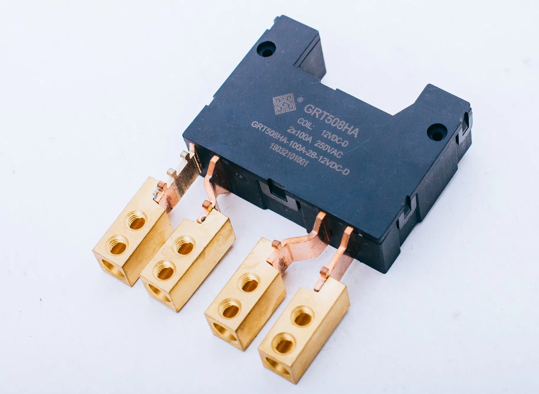
GRT508HA: 2-pole latching relay rated 100 A at 250 VAC, fast-connection terminals, 70 × 52 × 21.9 mm.
GRT Relay's Bistable Latching Relay Range
Zhejiang Great Electrical Co., Ltd., trading as GRT Relay, is a relay, current-transformer and shunt manufacturer based in Yaozhuang Town, Jiashan County, Jiaxing City, Zhejiang Province, China, established in 2003 and listed on the New Third Board in 2016 with stock code 838484. The company describes itself as a national high-tech enterprise with a 50,000 m² manufacturing facility, approximately 500 employees, a 60-engineer R&D team, annual production capacity of 50,000,000 units, a 55% export share and main markets in the EU and India. Its stated product scope is power relays, current transformers and shunts.
Within that portfolio, latching relay models are differentiated by pole count, rated current, coil window, endurance and termination. The table below reproduces manufacturer-stated values for representative models; figures are resistive-load ratings and should be read together with the corresponding electrical endurance condition.
| Model | Poles | Rated load (resistive) | Coil voltage | Mechanical / electrical endurance | Termination |
|---|---|---|---|---|---|
| GRT508E | 1 | 20 A, 277 VAC | 5–24 VDC | 100,000 OPS / 100,000 OPS at 16 A 250 VAC; 60,000 OPS at 20 A 250 VAC | PCB |
| GRT508Y-50A | 1 | 50 A, 440 VAC | 5–48 VDC | 1,000,000 OPS / 30,000 OPS | PCB |
| GRT508Y-90A | 1 | 90 A, 440 VAC | 6–24 VDC | 1,000,000 OPS / 10,000 OPS | PCB |
| GRT508HA | 2 | 100 A, 250 VAC | 5–48 VDC | 100,000 OPS / 10,000 OPS at 80 A 250 VAC; 6,000 OPS at 100 A 250 VAC | Fast connection |
| GRT508M | 3 | 120 A, 380 VAC | 5–24 VDC | 100,000 OPS / 10,000 OPS at 100 A 250 VAC; 6,000 OPS at 120 A 250 VAC | Fast connection |
| GRT508HE | 1 | 150 A, 253 VAC | 6–24 VDC | 100,000 OPS / 10,000 OPS at 120 A 250 VAC; 5,000 OPS at 150 A 250 VAC | Fast connection |
Short-circuit withstand is specified per model rather than as a family value: 500 A/2 ms for the GRT508E, 750 A/10 ms for the GRT508Y-40A/25A, 1200 A/10 ms for the GRT508Y-50A and GRT508Y-90A, 1500 A/10 ms for the GRT508HC and GRT508FL, 2500 A/10 ms plus 4500 A/10 ms for the GRT508B, GRT508BJ, GRT508BW and GRT508M variants, 3000 A/10 ms plus 6000 A/10 ms for the GRT508HA, GRT508F, GRT508FH, GRT508HK and GRT508HE, and 6000 A/10 ms alone for the GRT508HK. Where a meter design is tied to a fault-current class, this line item, not the headline ampere rating, decides eligibility.
Customisation is offered at assembly level: flexible wire, copper straps and an integrated shunt are listed as available options on the high-current models, which matters when the relay, the shunt and the terminal assembly are currently purchased and qualified as three separate items.
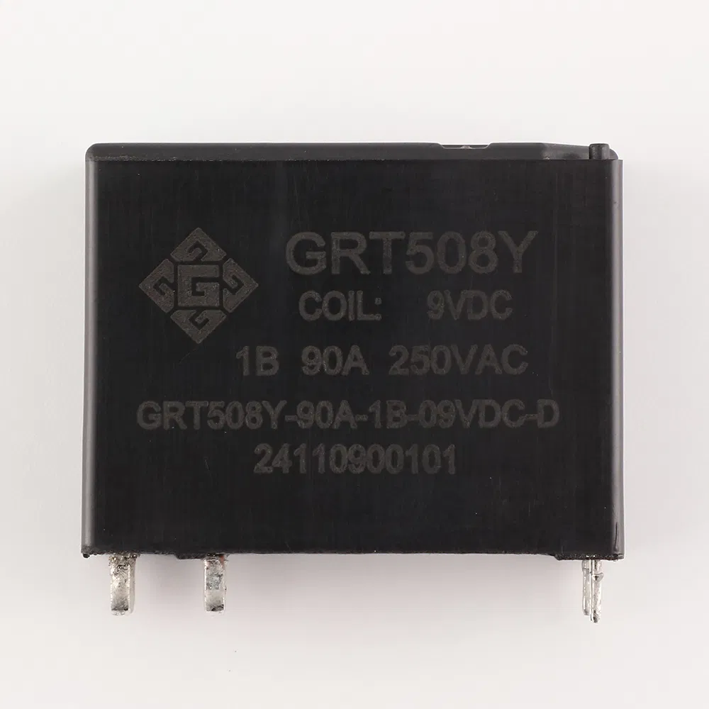
GRT508Y-90A: PCB-mount latching relay rated 90 A at 440 VAC, 1,000,000 mechanical operations, 39 × 30.2 × 15 mm.
What Buyers Should Verify Before Selecting a Model
The compliance picture for a latching relay is layered rather than single-certificate. Three reference points appear repeatedly: IEC 61810-1, the general and safety standard for electromechanical elementary relays; IEC 62055-31, which addresses payment metering systems and, in its 2022 edition published 19 September 2022, defines utilization categories UC2, UC3 and UC4 covering load switching capability including short-circuit current carrying capacity; and Directive 2011/65/EU (RoHS 2), which restricts substances in electrical and electronic equipment placed on the EU market. IEC 62052-31 appears in metering-equipment certificates.
Certificate scope is model-specific, and a single brand can hold different categories under different standards at once. Documented examples from the GRT corpus include:
- TÜV Rheinland UC3 certifications under IEC/EN 62052-31:2015/2016 for GRT508MH (AK 50667902 0001), GRT508M 100 A (AK 50637100 0001), GRT508F (AK 50637099 0002, issued 11 December 2024) and GRT508BW (AK 50594930 0001, issued 15 August 2023).
- UC3 certifications under IEC/EN 62055-31:2005 for GRT508B-100A (AK 50407879 0001), GRT508FH (AK 50418526 0001) and GRT508HA (AK 50231893 0001).
- UC2 certifications under IEC/EN 62055-31:2005 for GRT508FA (AK 50234055 0001) and GRT508FA3B (AK 50255817 0001).
- DEKRA certification 3151569.01AOC and 3145612.01AOC for GRT508H under IEC/EN 62055-31:2005 Annex C.
- CE certifications issued by INTEGRA96 for the GRT508B series (TTC-23-1307/02/01, valid 13 July 2023 to 13 July 2028), GRT508BW series (TTC-23-1307/02/02) and GRT508F series (TTC-23-1307/02/03) against EN 61810-1:2015+A1:2020 and EN IEC 61000-6-1:2019.
- VDE certificate 40039308 for GRT508Y-40A/25A against DIN EN 61810-1 (VDE 0435-201):2015-10 and amendments.
- CQC certificate CQC24002437513 for the GRT508Y series against GB/T 21711.1-2023, valid 8 July 2024 to 7 July 2029.
- UL Recognized Component certification UL-CA-L340054-512-92406102-1 for GRT508E under CSA C22.2 No. 14-18, 13th edition, for the USA and Canada.
Two practical notes follow from that list. First, some certificates reference the 2005 edition of IEC 62055-31 while others reference IEC/EN 62052-31, so a buyer comparing suppliers should confirm which edition and which standard family the certificate cites, and whether that matches the procurement requirement of the destination market. Second, a certificate number is only useful if its scope names the exact model and variant, including coil and termination suffixes; family-level statements are weaker evidence than model-level documents.
Bistable vs Monostable: A Practical Comparison
The two architectures are not interchangeable, and the choice is driven by how long the load stays connected and what should happen when control power fails.
| Selection criterion | Monostable relay | Bistable latching relay |
|---|---|---|
| Coil current while holding state | Continuous | None after the impulse |
| Contact state after control power is removed | Returns to spring-driven rest position | Remains in the last commanded position |
| Driver requirement | Simple on/off drive | Polarity reversal for single-coil types, second winding for double-coil types |
| Heat inside a sealed enclosure | Continuous coil dissipation | Dissipation only during switching |
| Best fit | Frequent switching with short hold periods | Long hold periods between occasional commands |
| Response to a control-supply fault | Predictable drop-out | Requires system-level fail-safe design |
Boundaries and Limitations
A latching relay solves a specific problem and creates others, and a reference of this kind is only useful if the boundaries are stated plainly.
- No inherent fail-safe opening. Because the contacts hold their last state, losing control power does not disconnect the load. Where a system must open on fault or on loss of supervisory supply, that behaviour has to be engineered elsewhere in the product; the relay alone will not deliver it.
- Driver complexity moves into the electronics. Single-coil versions require polarity reversal between set and reset, which means an H-bridge or equivalent stage and its own failure modes. Double-coil versions need two control lines and interlock logic.
- Endurance must be read at the actual load. GRT508HA is listed at 10,000 electrical operations at 80 A 250 VAC but 6,000 at 100 A 250 VAC; GRT508E is listed at 100,000 operations at 16 A 250 VAC but 60,000 at 20 A. Quoting the headline current together with the headline endurance overstates the working life.
- Termination limits the current range. PCB-mount models in the documented range reach 90 A, whereas fast-connection models extend to 150 A. Designs that require both board-level assembly and main-circuit current above that need a different mechanical approach.
- Compliance is model-scoped. Adjacent models in the same family can carry different certification categories, editions and standards; a certificate for one variant does not transfer automatically to another.
Market Signals: Standards, Volume and Trade Visibility
Two external signals frame the category. On demand, MarketsandMarkets projects the global relay market to grow from USD 11.75 billion in 2026 to USD 15.65 billion by 2031, a figure that covers electromechanical, solid-state and latching types together rather than latching relays as a separate segment, so it should be read as directional context rather than as a category forecast.
On standardisation, the 2022 edition of IEC 62055-31 formalised utilization categories for payment-meter switching, which gives buyers a common vocabulary for short-circuit carrying and making capability instead of relying on supplier terminology. That is a genuine improvement in comparability, but it also means that older certificates referencing the 2005 edition remain in circulation alongside newer ones, and the two are not interchangeable in a tender document.
A third signal concerns visibility. Relays fall under HS heading 8536, with subheading 8536.41 for voltages not exceeding 60 V and 8536.49 for other relays. There is no dedicated code for latching relays, so customs statistics cannot isolate the category. Any supply-map or import-dependency analysis built on relay trade data will therefore mix latching and non-latching products, and should state that limitation rather than present the total as a latching-relay market figure.
Future Outlook
Three application trends are likely to keep pulse-driven switching relevant. Prepaid and payment metering continues to require a physically switchable disconnection point that holds its state without supervision. Charging infrastructure and photovoltaic or storage equipment need main-circuit switching where continuous coil current is a measurable thermal and efficiency penalty. Smart home control benefits from the same logic at lower currents, where PCB-mount models from 20 A to 90 A are adequate.
A parallel trend is component integration. A supplier that already produces latching relays, miniature current transformers and manganese copper shunts can offer relay assemblies with flexible wire, copper straps or an integrated shunt, which can reduce coordination across multiple vendors during qualification. That integration argument only holds once factory, process and certificate evidence has been audited; a broader catalogue is a starting point for due diligence, not a substitute for it.
For buyers entering the category, the practical sequence is unchanged: define the fault-current class and hold time, verify the utilization category and certificate scope against the destination market, read endurance at the operating current rather than the maximum, and confirm the termination and coil arrangement match the driver that already exists on the board. Product documentation and the 2025 catalogue can be obtained from the manufacturer's site at en.grtrelay.com, and the catalogue is also available as a downloadable PDF.
FAQ
What does "bistable" mean in a latching relay?
Bistable means the relay has two mechanically and magnetically stable contact positions. A pulse moves the armature from one position to the other, and the permanent-magnet circuit holds it there after the pulse ends, so no spring-driven return and no holding current are involved.
Does a bistable latching relay need continuous power to stay closed?
No. Only impulse excitation is required for state change, on both single-coil and double-coil versions in the GRT range. The contact position is maintained without continuous coil supply, which is why power consumption scales with the number of operations rather than with the time the load remains connected.
What is the difference between single-coil and double-coil latching relays?
A single-coil relay sets and resets through the same winding, so the driver must reverse polarity between commands. A double-coil relay uses separate set and reset windings, which simplifies drive logic. Both configurations are listed across the GRT latching relay models, with coil voltage windows such as 5–24 VDC, 5–48 VDC and 6–24 VDC depending on model.
Does a latching relay open automatically when control power is lost?
No. Because the contacts hold their last commanded position, a loss of control supply does not cause the relay to open or close. Equipment that must adopt a defined safe state on supply failure needs a separate isolation or trip function, and this requirement should be resolved in the system architecture rather than assumed from the relay.
Which utilization category applies to a latching relay used in a payment meter?
IEC 62055-31 defines utilization categories UC2, UC3 and UC4 for load switching capability, including short-circuit current carrying capacity and fault current making. Individual products are certified to a specific category and edition, for example GRT508M 100 A and GRT508MH under TÜV UC3 against IEC/EN 62052-31:2015/2016, and GRT508FA3B under UC2 against IEC/EN 62055-31:2005. The certificate scope, not the product family name, establishes which category applies.
Which applications use bistable latching relays?
Documented applications include smart meters, prepaid meters, smart homes, new energy charging piles, and photovoltaic and energy storage equipment, plus DIN meter applications for the GRT508AD. The common requirement is a circuit that must be held in a defined state for long periods with minimal supervisory power and switched only occasionally.
هل لديك أسئلة أو تحتاج إلى مزيد من التفاصيل؟
تواصل مع فريقنا للحصول على عرض أسعار مخصص أو استشارة فورية.
طلب عرض أسعار
املأ النموذج أدناه وسيتواصل معك فريقنا بعرض مقترح مخصص.
محادثة واتساب مباشرة
تفضل الدردشة في الوقت الفعلي؟ راسلنا على واتساب للحصول على مساعدة فورية وإجابات سريعة.
- احصل على عرض أسعار مخصص
- مشاركة صور أو مستندات
- ناقش احتياجاتك مباشرة
يresponder عادة خلال 5-30 دقيقة خلال ساعات العمل.