
CNC Machining Fit for Robotic Arms and Drones: Choosing the Right Manufacturing Process
CNC Machining Fit for Robotic Arms and Drones: Choosing the Right Manufacturing Process
Subtractive metal removal is the only process that can hold some joints together. On other parts of the same drone or robot arm, it is the wrong answer. Here is how engineering and sourcing teams tell them apart.
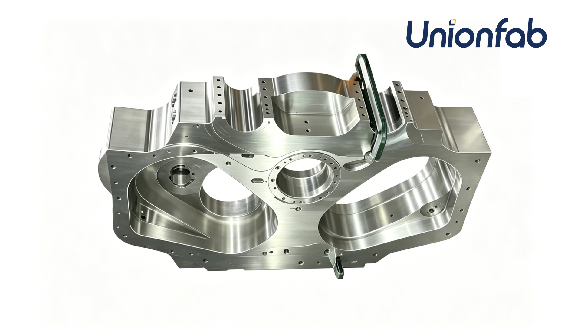
CNC gantry milling of a large structural component. Load-bearing geometry in robotics and unmanned systems is produced by the same subtractive category of processes.
Robotic arms and drones rarely fail because of software. Failures tend to start at a joint, a mount, or a bracket — one part where load path, wall thickness and hole position all converge. For teams building collaborative arms or unmanned platforms, the choice between CNC machining, additive manufacturing and sheet metal fabrication is therefore a design decision, not a purchasing formality. It determines whether an assembly still holds its geometry after thousands of load cycles.
This industry application analysis examines three things: the part classes in robotics and drone hardware where CNC machining is the required process; the cases where additive manufacturing or sheet metal is genuinely the better fit; and a documented low-volume example — a 50-piece production run of a joint connection component for a lightweight six-axis collaborative robotic arm, machined with multi-axis hole true position strictly held to ±0.0005 in (±0.0127 mm) and released with a full CMM inspection report.
The process question robotics and drone programs actually face
Modern robotics and drone programs rarely rely on a single manufacturing process. They use a sequence. A typical program moves from printed concept models to machined functional prototypes, then into production with a mix of processes: sheet metal chassis and frames, injection molded covers, and machined structural interfaces.
The rule that separates these categories is not part size or material alone. It is the function of the critical feature. Three questions usually settle it:
- Does the part carry load, or does it locate another component inside a kinematic chain?
- Does it seal, align or spin — in other words, does it have a functional surface with a fit requirement?
- Is its tolerance callout a general manufacturing tolerance, or a positional tolerance applied to a specific hole pattern against a datum?
When the first two answers are yes and the third identifies datum-referenced positional tolerances, the part usually belongs in CNC machining. When the part is a cover, a panel, a housing shell or an early form-and-fit model, it usually does not.
Where CNC machining is the required process in robotic and drone hardware
CNC machining is the standard baseline for aerospace and medical manufacturing, where quality and traceability requirements are formalized through standards such as ISO 9001, AS9100 and ISO 13485. The same logic applies to the load-bearing class of robotics and drone components: processes that produce near-net geometry do not, by themselves, guarantee where a bore ends up relative to a datum.
The capability envelope that governs these parts is defined by a small number of parameters:
| Parameter | Specification |
|---|---|
| Tolerance | ±0.0002 in (±0.005 mm), in accordance with ISO 2768 |
| Surface roughness | Up to 16 uin (0.4 µm) |
| Maximum part size | 4000 × 1500 × 600 mm |
| Minimum part size | 2 × 2 × 2 mm |
| Process range | CNC milling, CNC turning, 3-axis, 4-axis and 5-axis machining, EDM, wire EDM |
| Materials | Aluminum, stainless steel, carbon steel, titanium, brass, copper, high-performance exotic alloys, engineering plastics, insulation materials, rubber, ceramics |
| Lead time | 1 to 5 days |
Two parameters do most of the work in robotics. The first is the tolerance floor. A robot arm joint is a stack of fits: motor pilot, bearing seat, bracket bore, link interface. Every interface contributes positional error, and those errors accumulate along the arm. The second is multi-axis capability. Five-axis machining allows a multi-axis hole pattern and its datum faces to be produced in a single setup, which removes the re-fixturing error that builds up when a part is repositioned between machines for each new face.
Material choice reinforces the same conclusion. Aluminum 6061-T6 and 7075, titanium TC4, stainless steel 316L and 17-4PH, Inconel 625 and 718, and tool steels such as A2, D2, H13 and P20 all sit inside the machining envelope, alongside engineering plastics including POM, nylon, PC, PMMA, ABS and PEEK. Thin-wall ribs, sealing faces and press-fit bores in these materials are subtractive operations by nature.
Case evidence: a six-axis collaborative arm joint component
The clearest way to test the decision rule is against a real program. A Canadian intelligent robotics developer, working alongside an aerospace research institute, required a joint connection component for a lightweight six-axis collaborative robotic arm.
The production brief contained four constraints that, taken together, narrowed the process options sharply:
- The part had to withstand 5+ years under high inertial stress and load-bearing conditions.
- Multi-axis hole true position had to be strictly held to ±0.0005 in (±0.0127 mm).
- The design required 1.5 mm thin-wall milling from Aluminum 7075-T6.
- The order quantity was 50 pieces — a low-volume production run, not a one-off prototype.
The outcome: total robot arm weight was reduced by 35% while maintaining extreme joint torsional rigidity during rapid synchronized movements. Conformity was verified through a full CMM inspection report.
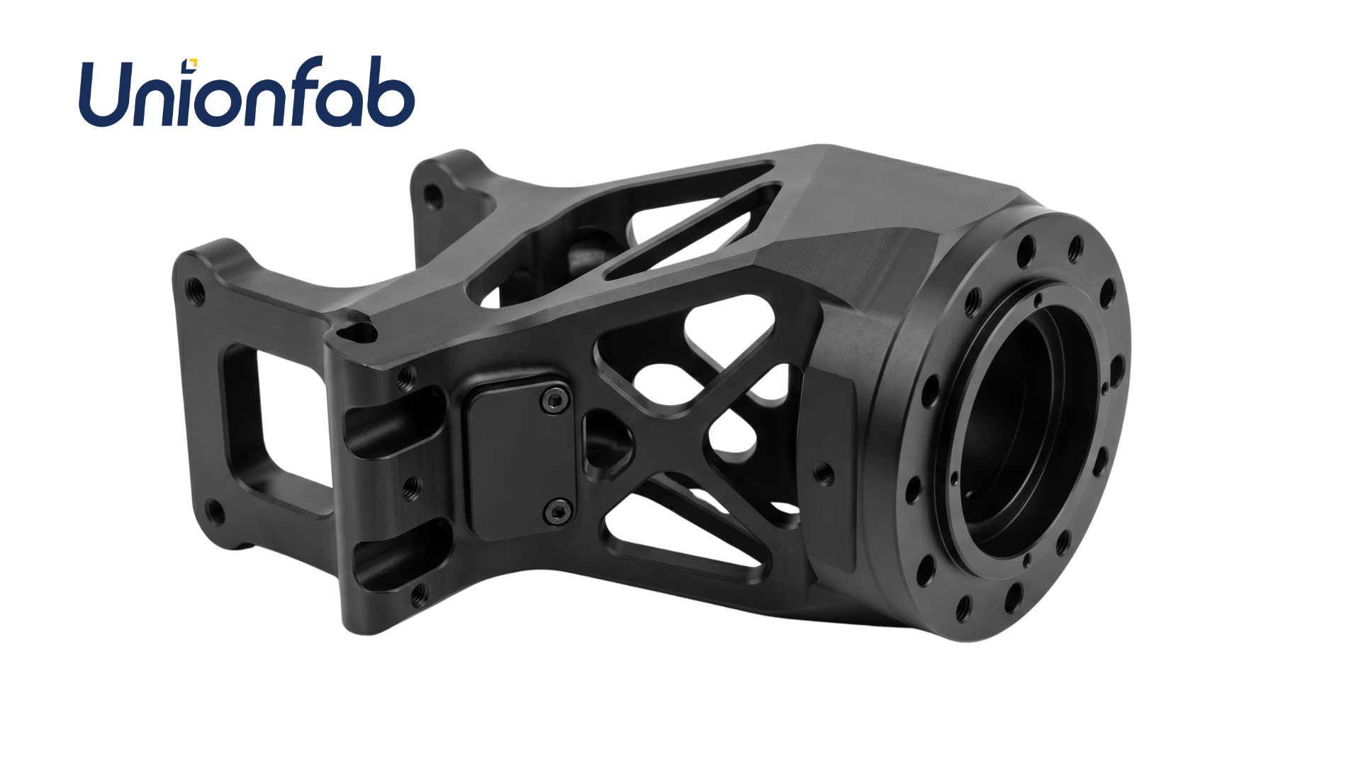
A machined joint bracket for a collaborative robotic arm. Multi-axis hole true position was held to ±0.0005 in (±0.0127 mm) across a 50-piece run.
Why this part sat firmly in the CNC column: the ±0.0005 in callout applied to a multi-axis hole pattern on a load-bearing joint, not to a cosmetic surface. Aluminum 7075-T6 at a 1.5 mm wall thickness combines high strength-to-weight with relatively low machinability, and it is prone to distortion when cutting forces are poorly controlled. Reproducing that geometry on a near-net process generally means machining the functional interfaces afterwards anyway, which returns the work to the same subtractive step. At a 50-piece quantity, establishing an additive route and then machining the critical features adds process steps without removing the tolerance problem.
Where additive manufacturing and sheet metal remain the better fit
A process recommendation that never says no is not a recommendation. For robotics and drone programs, several alternative routes cover most non-critical parts, and each has a defined place in the bill of materials.
3D printing and additive manufacturing. The available process range spans SLM, SLS, SLA, MJF, FDM, PolyJet, Binder Jetting, DLP and LCD. Plastic tolerances run at ±0.2% to 0.3% per mm with a minimum of ±0.1 mm, while metal tolerances run at ±0.2% to 0.4% per mm with a minimum of ±0.2 mm. Surface roughness ranges from 1.6 to 12.7 µm, the largest build envelope reaches 2100 × 700 × 800 mm in SLA, and turnaround can start from 1 day. Materials include PA12, PA11 and glass-filled nylons, TPU and TPE elastomers, and metals such as aluminum, 316L and 17-4PH stainless steel, titanium and Inconel. This is the right route for early form and fit, ducting, low-stress brackets, and internal geometry that no cutter can reach.
Sheet metal fabrication. Bending, laser cutting and stamping work to ISO 2768-m by default, produce Ra 3.2 µm surfaces, handle parts up to 1000 × 1200 mm, and can turn around in as few as 3 days, in materials such as SPCC, SECC and SGCC carbon steels, SUS304 and SUS316 stainless steel, aluminum 5052 and copper sheet. For drone airframes, avionics trays and robot controller enclosures, this is usually the correct and lower-cost route.
Cast and molded routes. Vacuum casting holds ±0.2% per mm with a lower limit of ±0.2 mm at Ra 1.6 to 6.3 µm for parts up to 1500 × 1000 mm, in 7 to 10 days — a useful bridge between prototype and production. Injection molding works to ISO 20457 for parts up to 1436 × 960 × 223 mm with lead times from 10 days, and rapid casting to ISO 8062-3 with lead times from 10 days. All three serve housings, covers and non-structural geometry.
| Part class | Recommended process | Governing specification |
|---|---|---|
| Load-bearing joint or mount with datum-referenced positional tolerance | CNC machining | ±0.0002 in (±0.005 mm) per ISO 2768; Ra up to 0.4 µm |
| Functional prototype for form and fit | 3D printing | Metals ±0.2% to 0.4% per mm (min ±0.2 mm); from 1 day |
| Frame, tray or enclosure panel | Sheet metal fabrication | ISO 2768-m; Ra 3.2 µm; up to 1000 × 1200 mm |
| Bridge to low-volume housing production | Vacuum casting | ±0.2% per mm (min ±0.2 mm); 7 to 10 days |
| High-volume plastic enclosure | Injection molding | ISO 20457; up to 1436 × 960 × 223 mm |
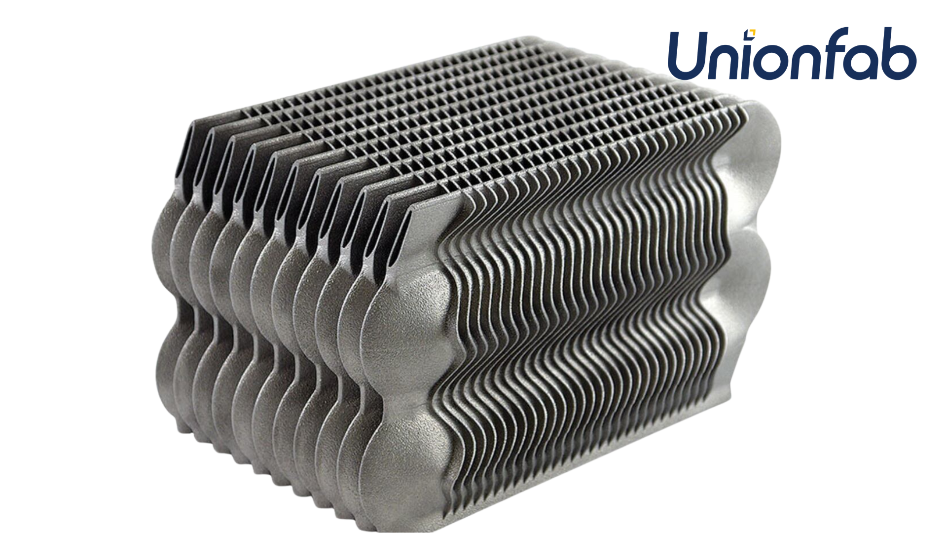
Metal additive parts serve early iterations and complex internal geometry. Load-bearing interfaces typically return to subtractive finishing.
All of these routes sit within the same manufacturing portfolio at Unionfab, alongside CNC machining. That matters for programs that need one supplier to move a part from prototype into production without re-qualifying a new vendor at every stage.
Limits and boundaries: where CNC machining stops being the right answer
Precision is neither free nor unlimited, and any credible process recommendation should state where it stops applying.
- Part size. The machining envelope tops out at 4000 × 1500 × 600 mm, with a minimum part size of 2 × 2 × 2 mm. Parts outside that range need a different route or a split design.
- Volume economics. At very high annual volumes, subtractive machining generally carries a higher per-unit cost than molding or casting, because machine time is consumed for every single part. That is exactly why injection molding (ISO 20457) and casting (ISO 8062-3) exist in a manufacturing portfolio — they become the economical answer once a design is frozen and volumes are high.
- Tolerance that is not actually needed. If a bracket only requires a general tolerance such as ISO 2768-m and a Ra 3.2 µm finish, sheet metal fabrication will normally be faster and cheaper than machining.
- Design for machinability. Machining removes material. Features that a cutter cannot reach — deep internal channels, re-entrant cavities, lattice structures — either need design adjustment or belong to additive processes.
- Cost drivers. Exotic alloys and tight tolerances both raise cost and lead time relative to standard aluminum work. A ±0.0002 in tolerance applied to a feature that does not functionally require it is an avoidable cost.
The practical rule is to match the process to the critical feature rather than to the whole assembly, and to accept that a robotics or drone product will legitimately use three or four processes across its bill of materials. The deployment context for this class of precision work spans automotive, medical, industrial equipment, drones, robotics and consumer electronics, with Germany among the typical application markets alongside the broader export footprint of the US, Canada, Germany, the UK, Spain, Italy, France and Sweden.
How the same discipline shows up in other automation builds
The robotics case is not isolated. Two other programs show the same pattern from different directions.
An industrial automation integrator and custom machinery manufacturer in Germany required a multi-station sensor and cylinder connection bracket for automotive final assembly lines, engineered for 8+ years of high-frequency continuous operation. The batch was 15 pieces — a low-volume prototype quantity. A single-piece prototype with no MOQ was delivered in 48 hours, and overall flatness was controlled within 0.05 mm using modular quick-change tooling. The result was zero vibration displacement on the assembly line. Here the value of CNC machining was not only tolerance but the ability to iterate at a quantity of one and then scale the same geometry.
A precision CNC machine tool manufacturer and medical device OEM in the United States runs a 500-piece annual batch of a transmission fixing base and pilot alignment mount for medical CT scanner servo drives, in continuous high-speed and high-heat-dissipation operation for 10+ years. The detail worth noting is reverse dimension compensation applied in CAM programming before anodizing, to prevent thread seizure, combined with manual Go/No-Go gauging and physical assembly simulation before shipment. The lesson transfers directly to robot joints: when a coating changes the dimension of a threaded or fitted interface, that compensation has to be built into the program rather than discovered at assembly.
Unionfab in this context
Unionfab AM Technology (Shanghai) CO., Ltd. is a global on-demand digital manufacturing platform rooted in Uniontech, a manufacturer of SLA 3D printing equipment, and was founded in 2014. It operates 10 self-owned factories across an 80,000 m² footprint, with 1,000+ industrial 3D printers and 400+ CNC machines, serving 80,000+ customers across 170+ countries, including the USA, Canada, Germany, the UK, Spain, Italy, France and Sweden. The engineering organization includes 100+ engineers, and export accounts for 100% of output.
For the robotics and drone part class described above, the relevant capability is the CNC envelope: tolerance to ±0.0002 in (±0.005 mm) in accordance with ISO 2768, surface roughness up to 0.4 µm, part sizes from 2 × 2 × 2 mm to 4000 × 1500 × 600 mm, and lead times from 1 to 5 days. This is supported by OEM production, customization across dimensions, materials, tolerances, finishes, logo engraving and text marking, a minimum order quantity of 1 unit, and monthly capacity of 150,000+ units.
On quality and delivery: a quality complaint rate below 0.5%, on-time delivery above 95%, and certifications including ISO 9001, ISO 13485, ISO 14001 and IATF 16949. Default inspection covers 100% dimensional and surface inspection, form tolerance checks, burr and sharp edge inspection, thread and fastener go-no-go gauging, and internal defect inspection; post-heat-treat hardness testing, CMM and 3D scanning are available as add-ons, with results held in a digital QC repository. Production runs in a factory ambient temperature clean environment (Class 8 cleanliness) under 24/7 continuous operation, supported by DFM consultation, automated quoting, order tracking and 24/7 online support. Alongside CNC machining, the portfolio includes 3D printing, vacuum casting, injection molding, sheet metal fabrication and rapid casting — the combination that lets a single part move between processes as a program matures.
Market trend: capacity is expanding, differentiation is moving to evidence
Several verified market signals explain why this process decision is becoming more consequential rather than less.
- The global CNC machining services market was valued at USD 93.4 billion in 2025 and is projected to reach USD 174.6 billion by 2034, a CAGR of 7.2% (Dataintelo).
- The global CNC machine market was valued at approximately USD 73.5 billion to USD 83.7 billion in 2024, with the range reflecting differences in report scope between Fortune Business Insights and Market Research Future.
- Asia Pacific held approximately 55.7% of CNC machine market revenue in 2025, driven by automotive and electronics manufacturing (Fortune Business Insights).
- The automotive segment accounted for 38.42% of CNC applications in 2026, largely on the strength of high-volume precision requirements for EV components (Fortune Business Insights).
- China machine tool industry exports reached USD 23.18 billion in 2025, a 6.7% year-over-year increase, with machining centers among the leading categories (China Machine Tool and Tools Builders Association).
- AI-driven CNC systems can reduce machine downtime by up to 40% and material waste by approximately 30% through predictive maintenance and real-time toolpath optimization (MarketsandMarkets).
The interpretation for robotics and drone buyers: machining capacity and precision are becoming more widely accessible, including for mid-size programs that cannot justify dedicated tooling. As availability increases, the differentiator shifts from access to machines toward verifiable evidence — documented inspection, traceable materials, and a process route that can scale from 15 pieces to 150,000 units a month without changing supplier.
Future outlook
The likely direction for robotics and drone manufacturing is not a single winning process but a more deliberate hybrid program: additive for early iterations and complex internal geometry, CNC machining for load-bearing and datum-referenced interfaces, sheet metal for frames and enclosures, and molding or casting once volumes justify tooling. Two shifts will accelerate this. First, quoting and DFM feedback are becoming digital and immediate, which lowers the cost of testing a process route before committing to it. Second, inspection data is becoming a deliverable rather than a courtesy — CMM reports and digital QC repositories are increasingly part of the purchase record.
For teams specifying parts today, the defensible position is the specific one: name the feature that drives the requirement, state the tolerance it must hold, and select the process that can prove it.
FAQ
When is CNC machining required for a robotic arm or drone part, rather than optional?
CNC machining is required when the part carries structural load, locates another component inside a kinematic chain, or provides a sealing or fit surface with a datum-referenced tolerance. Those requirements appear as positional tolerances on specific features plus surface roughness limits. Unionfab CNC machining holds ±0.0002 in (±0.005 mm) in accordance with ISO 2768, with surface roughness up to 0.4 µm. Where a general tolerance such as ISO 2768-m and a Ra 3.2 µm finish are sufficient, sheet metal fabrication or additive manufacturing may be adequate and more economical.
What positional tolerance can realistically be held on a robot arm joint component?
A documented case from a Canadian intelligent robotics developer and aerospace research institute involved a joint connection component for a lightweight six-axis collaborative robotic arm, where multi-axis hole true position was strictly held to ±0.0005 in (±0.0127 mm) across a 50-piece low-volume run, verified with a full CMM inspection report. Because the machining tolerance floor is ±0.0002 in (±0.005 mm) per ISO 2768, the case value sits inside the stated capability rather than at its limit.
Is CNC machining economical for 15- to 50-piece runs?
Yes. Unionfab CNC machining operates with a minimum order quantity of 1 unit, lead times from 1 day and monthly capacity of 150,000+ units. Two documented examples illustrate the range: a 50-piece production run of six-axis collaborative robotic arm joint components for a Canadian robotics developer, and a 15-piece prototype batch for a German industrial automation integrator, where a single-piece prototype with no MOQ was delivered in 48 hours and overall flatness was held within 0.05 mm.
How can a buyer verify that a supplier actually met the specified tolerance?
Default inspection at Unionfab includes 100% dimensional and surface inspection, form tolerance checks, burr and sharp edge inspection, thread and fastener go-no-go gauging, and internal defect inspection. Post-heat-treat hardness testing is available on request, and CMM and 3D scanning are available as add-ons, with results held in a digital QC repository. The robotic arm joint case was released against a full CMM inspection report. Buyers should ask for the inspection method and the record, not only a conformance statement.
Where does CNC machining stop being the right process?
Four boundaries are worth stating. Part size is limited to 4000 × 1500 × 600 mm maximum and 2 × 2 × 2 mm minimum. At very high annual volumes, molding (ISO 20457, parts up to 1436 × 960 × 223 mm, lead times from 10 days) or casting (ISO 8062-3, lead times from 10 days) generally becomes the more economical route. Parts that only require a general tolerance such as ISO 2768-m are usually better served by sheet metal fabrication, which handles up to 1000 × 1200 mm with lead times from 3 days. And features that no cutting tool can reach, such as internal channels or lattice structures, belong to additive processes.
For buyers evaluating this class of work in detail, Unionfab publishes its full capability, material and certification profile in a downloadable manufacturing brochure.