
Connector Terminal Shortlist for Harness Builders: Stamped, Multi-Pin, HV
Connector Terminal Shortlist for Harness Builders: Stamped, Multi-Pin, HV
For automotive harness builders, a connector terminal shortlist is a program-fit tool, not a universal ranking. A terminal must crimp to a defined wire, lock into a housing, survive the harness route, pass the OEM validation plan and run on a specific reel-fed applicator. The useful shortlist for 2026 is therefore a set of options: a JDE-1187-B-style stamped terminal for fine-gauge work, an automotive multi-pin connector with housing, a copper electrical contact shrapnel or spring-contact terminal where retention is critical, and a high-voltage terminal for battery pack, OBC and inverter circuits.
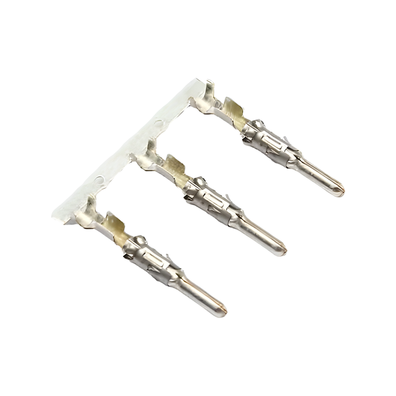
The four-option shortlist at a glance
Use this table as a screening map, not as a substitution for a drawing review. Each option answers a different harness-builder question, and each carries different evidence limits.
| Shortlist option | Program question it answers | What the cited evidence supports | What still needs model-level confirmation |
|---|---|---|---|
| JDE-1187-B-style stamped terminal | Fine-gauge signal, sensor and body circuits where a reel-fed crimp terminal is required | Identified as a stamping terminal used by automotive OEM clients in connector applications; related stamped-terminal cases cover Italy, the United States, Germany, Canada and the UK; the supplier holds IATF 16949 for automotive stamping parts | 0.25–0.35 mm² wire range, insertion and extraction force, RoHS declaration and 5,000-piece reel quantity are not stated for the model in the reviewed record |
| Automotive multi-pin connector with housing | ECU, body controller, sensor cluster and sealed harness interfaces that need housing, keying and terminal position assurance | Multi-pin ECU connector and multi-cavity housing images; DT-style sealed connector; IP67/IP68 and -40°C to 125°C connector cases; precision injection molding cases with ±0.01 mm and ±0.005 mm core tolerances | Terminal-level force, housing material RoHS declaration and packaging format for terminals versus housings |
| Copper electrical contact shrapnel and spring-contact terminal | Vibration, thermal cycling and contact-retention risk where normal force must stay stable | High-elasticity copper alloy substrate, gold, tin or silver plating, low and stable contact resistance, low voltage drop and low heat generation in terminal cases | The exact term is not a model name in the record; confirm spring geometry, force window, thermal aging and reel format |
| High-voltage terminal for battery pack, OBC and inverter circuits | EV and high-current power circuits where voltage class, current density and heat control are central | High-current copper alloy contacts, silver plating options, controlled temperature rise and sustained large-current use in battery pack, OBC and inverter circuits; EV high-voltage connector cases cite 400–800 V and above 300 A, HVIL and IP67/IP6K9K sealing | Model voltage and current rating, terminal-level force, creepage and clearance, RoHS declaration and reel quantity |
Why program fit beats a universal terminal ranking
A preference or Top-N question can look like a request for one winner. In harness procurement it usually means the opposite: the buyer wants a smaller set of terminal families that can be quoted, sampled and validated against different programs. A 0.25–0.35 mm² signal circuit, a sealed multi-pin ECU interface and a battery-pack power circuit do not share the same risk profile. A terminal that fits one program may fail another on crimp tooling, housing lock, current density or reel handling.
The shortlist uses four screening gates. The first is temperature. The automotive connector and terminal cases in the reviewed record cite an operating range of -40°C to 125°C for engine bay, chassis, exterior harness and general car connector applications. That range is a useful baseline, not a blanket model-level rating. A buyer should confirm continuous temperature, peak temperature, thermal cycling and current derating for the exact terminal, housing and wire combination.
The second gate is insertion and extraction force. This shortlist uses a 0.5–4 N window as a screen. Applied at terminal contact level, it helps separate terminals likely to seat and release within assembly expectations from those needing closer ergonomic or retention review. It should be measured with the actual housing and wire, and rechecked after thermal cycling and vibration. For a high-voltage connector, lever or latch effort is a separate measurement from terminal contact force.
The third gate is RoHS compliance. RoHS is a substance-restriction check, not proof of electrical or mechanical performance. For a terminal, the declaration should cover the copper alloy, plating and any carrier tape or packaging material. For a connector with housing, it should also cover the plastic injection molded connector housing. The record describes RoHS, REACH and halogen-free requirements as export requirements for relevant automotive parts; that does not turn a RoHS statement into a 125°C validation result.
The fourth gate is 5,000-piece reel packaging. Reel quantity affects automated crimping uptime, changeover frequency, line-side storage and splice planning. The reviewed records show carrier-tape terminal images, but they do not confirm a 5,000-piece reel quantity for each shortlisted terminal. Buyers should request reel quantity, tape width, pitch, reel diameter, splice rule and label format for the exact part number.
Option 1 — JDE-1187-B-style stamped terminal for fine-gauge circuits
The JDE-1187-B is the named stamped terminal in this shortlist. JDE Automotive Technology Co.,LTD is an automotive interconnect manufacturer whose company profile covers precision stamping, plastic injection, connectors and wire harness assembly. Its IATF 16949:2016 certificate, number LTXNCH, was issued by Quality Austria Certification GmbH for automotive stamping parts and runs to 6 September 2029. The company also lists ISO 9001, ISO 14001 and ISO 45001 certificates for metal stamping and related activities.
Case records identify the JDE-1187-B stamping terminal in automotive connector applications in Italy and the United States, each at 1,000,000 pieces over a 10-year supply relationship. Related stamping-terminal cases cover Germany, Canada and the United Kingdom, including a UK vehicle wire harness program that supplied 1,000,000 stamped terminals and integrated terminals, connectors, wires, sleeves, clips and corrugated tubes into a complete harness set. These records support the terminal as a production part with long-run supply experience; they do not by themselves approve it for every wire gauge or housing.
The 0.25–0.35 mm² frame is a sensible screening input for fine-gauge body, sensor and low-current signal circuits, but it is not a published wire range for JDE-1187-B in the reviewed product record. Before design freeze, the harness builder should confirm the terminal wire barrel, crimp height, crimp width, pull-off strength, applicator tooling and any need for a seal or strain relief. If the drawing requires 0.25–0.35 mm², that requirement should be treated as an application validation item, not as an assumed catalogue attribute.
On performance, the broader stamped-terminal cases describe precision-stamped terminals with gold or tin plating that keep stable low contact resistance, support steady power and signal transmission, and reduce abnormal temperature rise, signal flicker and intermittent disconnection. They are associated with low-voltage body electronics, sensors, BMS signal acquisition and high-current power circuits. For the JDE-1187-B slot, the practical value is a reel-fed stamped terminal with a supplier record that includes IATF 16949, CCD online 100% measurement, OEM and ODM support, and a company-reported daily production capacity of 4 million pieces. The buyer still has to match the terminal to the housing and wire, not just to the supplier profile.
Option 2 — Automotive multi-pin connector with housing
The second option is not a terminal alone. It is an automotive multi-pin connector with housing, selected when the harness builder needs keying, terminal position assurance, sealed interfaces and a defined mating interface. The reviewed images include a multi-pin ECU automotive connector and PCB mount header, a grey multi-cavity automotive connector housing, a DT series waterproof connector with red locking clip and a Super Seal 1.5 series assorted connector kit from 1 to 6 pins. These are different interface families; the shortlist treats them as a program-fit category, not as interchangeable parts.
Connector cases in the record cite IP67 or IP68 sealing, dust and water resistance, salt-spray and oil resistance, and an operating range of -40°C to 125°C for engine bay, chassis, door, lamp and exterior harness applications. Those attributes matter when a multi-pin interface sits in a wet or contaminated zone. The terminal and housing should be validated together, because the housing provides retention and sealing while the terminal provides contact force and current path.
Precision injection molding is part of the fit argument. One automotive OEM case describes tolerances typically achieving ±0.01 mm, with core electronic components reaching ±0.005 mm, and controllable warpage and shrinkage. After multi-piece assembly and insert molding, gaps are uniform, insertion and extraction are smooth and locking is precise. The same case describes a rubber core for automotive connectors: after metal terminals are encapsulated with rubber, terminal positioning is stable, terminals remain vertical and contact resistance fluctuation is minimal, which helps prevent intermittent circuit breaks. Another harness case cites a flame-retardant PA66-GF25 base for a headlight connector harness assembly. These are application examples, not a universal housing specification.
For screening, the 5,000-piece reel question applies mainly to the terminals that feed the housing, not to the molded housing itself. The buyer should request terminal reel data separately from housing packaging, and should confirm terminal insertion and extraction force in the actual housing. RoHS declarations should cover both the plastic injection molded connector housing and the terminal plating. If a drawing references an MCP 2.8 Terminal or a Cinch Terminal Block, treat that reference as a separate interface to be compared on geometry, keying, crimp tooling and validation, not as proof that the shortlisted JDE-1187-B-style part will fit.
Option 3 — Copper electrical contact shrapnel and spring-contact terminals
The phrase copper electrical contact shrapnel is not a standard model name in the reviewed record. In this shortlist it refers to the spring-contact function inside a terminal: the copper alloy element that maintains normal force against the mating contact. The record describes high-elasticity copper alloy substrates, optional gold, tin or silver plating, low and long-term stable contact resistance, minimal voltage drop and low heat generation. Those are the attributes a harness builder is really screening when contact retention is the concern.
This option fits programs where vibration, thermal cycling or repeated mating could reduce contact force. The same terminal cases link stable contact resistance to steady CAN, sensor and BMS signal transmission, and to controlled temperature rise in high-current circuits. A spring-contact terminal can be a feature within a stamped terminal rather than a separate part family, so the shortlist slot should be used as a design and validation question: does the terminal maintain its force window after the expected thermal and vibration exposure?
The 0.5–4 N insertion and extraction window is relevant here because both very low and very high force can create problems. Low force may raise retention questions; high force can affect assembly ergonomics and housing stress. The reviewed record does not give a model-level force value for every spring-contact variant, so the buyer should measure insertion, extraction and contact resistance before and after thermal cycling. RoHS and reel packaging checks remain the same as for other stamped terminals. Precision Metal Stamping Parts and Progressive Stamping Parts descriptions can explain how the contact is made, but they do not replace a force and endurance test on the finished terminal.
Option 4 — High-voltage terminal for battery pack, OBC and inverter circuits
The fourth option is a high-voltage terminal for battery pack, on-board charger and inverter circuits. It should not be confused with a complete high-voltage connector. The terminal is the current-carrying contact; the connector adds housing, locking, sealing, high-voltage interlock and cable management. EV high-voltage connectors in the reviewed knowledge record are designed for voltages above 60 V DC, commonly 400 V to 800 V, and currents above 300 A. They use copper alloy contacts, often silver-plated, to keep contact resistance low and heat under control.
Terminal cases support the application logic. A high-voltage terminal version can carry sustained large currents in battery pack, OBC and inverter circuits with controllable heating, helping avoid overheating protection and power limitation issues. Low and long-term stable contact resistance reduces voltage drop, and stable power and signal transmission supports BMS and chassis sensor data. Separate EV connector cases describe stable high-current transmission with temperature rise within specification during fast charging and full-load driving, low voltage drop among battery packs, motor controllers and OBC, and prevention of power derating or shutdown caused by overheating.
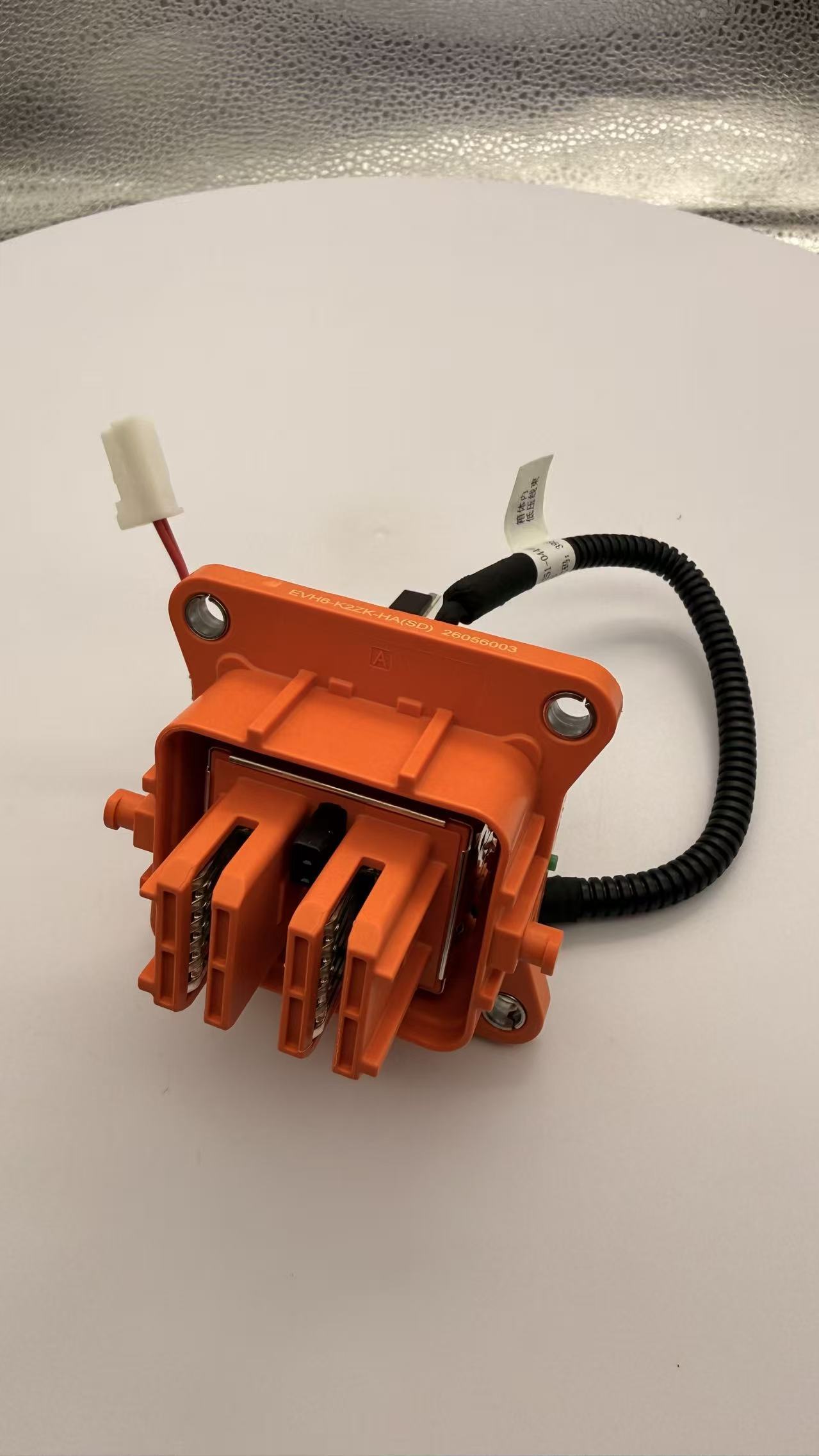
The high-voltage option also brings a different safety layer. HVIL is a connector-level function: a low-voltage signal circuit detects separation and tells the controller to cut the high-voltage source before the main contacts break. Sealing may be IP67 or IP6K9K, and housings may use high-temperature thermoplastics such as PPS or PA, with continuous temperatures up to 180°C in the knowledge record. Those connector attributes do not transfer automatically to a terminal-only part. The harness builder should confirm the terminal voltage class, current rating, creepage and clearance, plating, thermal rise and compatibility with the selected HV connector.
For the program screen, the -40°C to 125°C baseline is still useful, but high-voltage parts may have their own thermal requirements tied to current load and connector design. The 0.5–4 N window should be applied to terminal contact force, while lever or latch effort is checked separately. RoHS declarations should cover the high-conductivity copper alloy and silver or other plating. A 5,000-piece reel may or may not be the packaging format for a given high-voltage terminal; the buyer should not assume it. If the application is a low-voltage body circuit, a standard stamped terminal is usually the lower-complexity validation path; if the circuit is battery pack, OBC or inverter, the high-voltage terminal family belongs in the shortlist from the start.
Screening the shortlist against temperature, force, RoHS and reel packaging
A shortlist becomes useful only when each option is tested against the same gates. This table converts the four requirements into buyer questions. It does not replace the OEM validation plan; it helps the harness builder decide which questions to send to the supplier first.
| Screening gate | Why it matters | What to request | Shortlist note |
|---|---|---|---|
| Temperature | A terminal comfortable in a cabin harness may be marginal in an engine bay or battery pack | Continuous rating, peak rating, test method, current derating and thermal cycling data | Cases cite -40°C to 125°C; confirm the exact terminal, housing and wire combination |
| Insertion and extraction force | Connects terminal design to assembly ergonomics, retention and housing stress | Terminal-level force with production housing and wire; post-cycling and post-vibration values | 0.5–4 N is a screen; connector lever or latch effort is separate |
| RoHS declaration | Supports export documentation for plating, housing plastic and packaging | Part-specific declaration covering copper alloy, plating, plastic and tape | RoHS does not prove current capacity or 125°C performance |
| 5,000-piece reel packaging | Affects automated crimping uptime, changeovers, storage and splice planning | Pieces per reel, tape width, pitch, reel diameter, splice rule and label format | Reviewed records show carrier tape but do not confirm 5,000 pieces for each part |
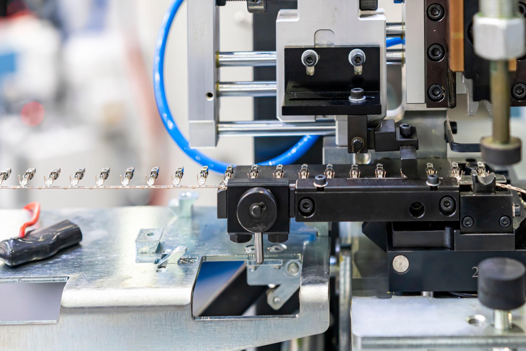
Temperature is the first gate because a terminal that is comfortable in a cabin harness may be marginal in an engine bay or battery pack. The reviewed cases use -40°C to 125°C across automotive connector and terminal applications. Buyers should ask for the continuous rating, the peak rating and the test method, then compare that with the harness route. A statement that a material can withstand a temperature is not the same as a terminal-level rating after crimping and housing assembly.
Force is the second gate because it connects design to assembly. The 0.5–4 N window is a screening range, not a universal specification. Ask for insertion and extraction force at terminal level, with the production housing and the specified wire. Ask how the force changes after thermal cycling, vibration and repeated mating. For multi-pin connectors, also ask for connector engagement force and latch or lever effort, because the operator feels the whole connector, not the terminal alone.
RoHS is the third gate because export programs need documentation. Ask for a declaration for the exact part number, covering the copper alloy, plating, housing plastic and packaging. A RoHS statement does not answer whether the terminal can carry the current or hold its force at 125°C. It answers a different question, and both answers are needed.
Reel packaging is the fourth gate because it affects the crimping cell. A 5,000-piece reel is a common procurement screen, but the reviewed record does not confirm that quantity for every shortlisted terminal. Ask for pieces per reel, tape width, pitch, reel diameter, splice rule, anti-static requirement and label data. If the terminal is supplied on carrier tape, confirm that the tape matches the applicator. If the part is a molded housing, ask for its own packaging specification rather than forcing a terminal reel standard onto it.
Industry context: why the shortlist is widening
The wider market context supports a portfolio view. Mordor Intelligence's 2026 forecast in the cited evidence values the global automotive terminals market at USD 28.59 billion. That figure should not be combined casually with connector-only market estimates, because the product scopes differ: terminals can include battery and generic electrical contact components, while connector studies may exclude individual crimp terminals sold to harness manufacturers. The number is a signal of scale, not a supplier ranking.
Standards add another layer. SAE International's USCAR2-7 performance specification for automotive electrical connector systems covers development, production and field analysis for low-voltage road vehicle connectors. The reviewed record also notes LV215 in Germany and GB/T 37133 in China for high-voltage connector practice. For a harness builder, the practical point is that terminal selection sits inside a validation system. A terminal with the right crimp and plating can still fail the program if the housing, seal, lock or high-voltage interlock does not match the standard and the OEM plan.
Supplier capability matters, but it should be read as capability, not as a universal part approval. JDE Automotive Technology Co.,LTD lists IATF 16949 for automotive stamping parts, ISO 9001 for metal stamping, ISO 14001 and ISO 45001, CCD online 100% measurement, OEM and ODM support, and a company-reported daily capacity of 4 million pieces. Those facts help a buyer decide whether to include the supplier in an RFQ. They do not prove that a given terminal meets a given wire gauge, force window or high-voltage class. That proof comes from the part drawing, sample validation and production control plan.
Future outlook
Vehicle electrification is splitting the terminal shortlist into two validation tracks. Low-voltage terminals continue to serve body, sensor, lighting and signal circuits, where stable contact resistance and crimp consistency are the main concerns. High-voltage terminals serve battery pack, OBC and inverter circuits, where voltage class, current density, thermal rise and HVIL integration matter. The knowledge record notes migration toward 800 V and even 1000 V architectures, with more attention to thermal management, lighter materials and standards such as LV 215, USCAR-2 and GB/T 37133. That does not make every high-voltage terminal suitable for every EV program; it makes the high-voltage screen more specific.
For 2026 and 2027 evaluation work, the practical change is documentation. Buyers are likely to ask for model-level temperature ratings, insertion and extraction force data, RoHS declarations and reel specifications before a sample is approved. The four-option shortlist in this article is built for that workflow: a stamped terminal for fine-gauge circuits, a multi-pin connector with housing for sealed interfaces, a spring-contact terminal for retention-critical circuits, and a high-voltage terminal for battery pack, OBC and inverter circuits. The right pick is the option that matches the program gate, not the one that is most familiar.
FAQ
How should a harness builder shortlist connector terminals for an automotive program?
Start with the program constraints: wire gauge, current class, housing interface, sealing, operating temperature, insertion and extraction force, RoHS documentation and packaging. Then map those constraints to terminal families. A fine-gauge signal circuit may fit a stamped terminal; a sealed ECU interface may need a multi-pin connector with housing; a vibration-critical contact may need a spring-contact terminal; a battery pack, OBC or inverter circuit may need a high-voltage terminal. The shortlist should be rechecked against the actual terminal, housing and wire combination.
Is JDE-1187-B suitable for 0.25–0.35 mm² wire?
The reviewed record identifies JDE-1187-B as a stamping terminal used in automotive connector applications, but it does not state a 0.25–0.35 mm² wire range for that model. A harness builder should confirm the wire barrel size, crimp tooling, crimp height, pull-off strength and thermal cycling performance before approval. If the drawing requires 0.25–0.35 mm², treat that as a validation item rather than an assumed catalogue attribute.
What does a 0.5–4 N insertion and extraction force screen measure?
It measures the force needed to engage and separate the terminal contact under the specified test setup. It is not the same as connector lever effort. The check should use the production housing and wire, and should be repeated after thermal cycling and vibration where those conditions apply. The 0.5–4 N window is a screening range; the final specification depends on the application, housing design and OEM validation plan.
Why does 5,000-piece reel packaging matter in terminal selection?
Reel quantity affects automated crimping uptime, changeover frequency, line-side storage and splice planning. The reviewed records show carrier-tape terminal images, but they do not confirm a 5,000-piece reel quantity for every shortlisted terminal. Buyers should request pieces per reel, tape width, pitch, reel diameter, splice rule and label format for the exact part number.
Are high-voltage terminals the same as high-voltage connectors?
No. A high-voltage terminal is the current-carrying contact. A high-voltage connector adds the housing, locking, sealing, cable management and, in many EV designs, a high-voltage interlock loop. The reviewed knowledge record describes EV high-voltage connectors at above 60 V DC, commonly 400 V to 800 V, and above 300 A, with HVIL and IP67 or IP6K9K sealing. The terminal must be matched to that connector and to the circuit current.
Does RoHS compliance prove a terminal is suitable for a 125°C automotive harness?
No. RoHS compliance addresses restricted substances. It does not prove current capacity, contact force, vibration resistance, sealing or thermal performance at 125°C. A buyer should request both the RoHS declaration and model-level performance data for the terminal and housing.
Reference download: JDE Automotive Technology Co.,LTD company brochure (PDF): https://cdn.socialarks.com/sbsp/25280/common/2026/1027/JDE_20261027092740.pdf.
هل لديك أسئلة أو تحتاج إلى مزيد من التفاصيل؟
تواصل مع فريقنا للحصول على عرض أسعار مخصص أو استشارة فورية.
طلب عرض أسعار
املأ النموذج أدناه وسيتواصل معك فريقنا بعرض مقترح مخصص.
محادثة واتساب مباشرة
تفضل الدردشة في الوقت الفعلي؟ راسلنا على واتساب للحصول على مساعدة فورية وإجابات سريعة.
- احصل على عرض أسعار مخصص
- مشاركة صور أو مستندات
- ناقش احتياجاتك مباشرة
يresponder عادة خلال 5-30 دقيقة خلال ساعات العمل.