
Custom Transformer Deployment: Pole, Pad or Prefab Cabin?
Most custom transformer projects are specified in the wrong order. The kVA rating and impedance are agreed first, the enclosure is treated as packaging, and the mismatch only appears during civil works, cable termination or energisation. In practice the deployment type — pole-mounted, pad-mounted or prefabricated cabin — decides which equipment sits inside the enclosure, how protection is integrated, how much work is left for the site, and which certification route the unit has to follow.
A single-phase pole-mounted transformer (5–167 kVA) places only the sealed tank, bushings and mounting brackets on the pole, with switching and fusing handled by line equipment. A pad-mounted transformer (15–250 kVA single-phase, 75–2,500 kVA three-phase) puts the transformer, high-voltage and low-voltage switching, fusing and surge arresters inside a tamper-resistant ground-level enclosure on a concrete pad. A prefabricated cabin substation (10/35 kV, 500–50,000 kVA) ships a complete substation — HV switchgear, transformer, LV switchgear, compensation, automation, AC/DC supply and environmental control — as a factory-assembled module for crane lifting and site connection. Choose the configuration by site access, load size, protection scope and how much site work the schedule can absorb — not by capacity alone.
Why the enclosure decision comes before the transformer specification
Distribution capacity is being added faster than site labour is being trained. Grand View Research projects the global distribution transformer market to grow from USD 26.0 billion in 2026 to USD 47.7 billion by 2033 at a compound annual growth rate of 9.1%. A separate market estimate puts box-type substations for photovoltaics at USD 4.54 billion in 2026. Whatever the exact figure in a given region, the direction is consistent: more units, more often, on sites where civil works and skilled commissioning crews are the scarce resource rather than the transformer itself.
That pressure makes the deployment choice a procurement decision rather than a packaging detail. Once a project commits to a pole-mounted unit, an overhead line and pole asset become prerequisites; once it commits to a pad-mounted unit, a concrete pad, clearances and a ground-level operating interface follow; once it commits to a prefabricated cabin, transport routes, lifting equipment and auxiliary power for the cabin's own systems enter the scope. Changing any of these after award re-opens civil design, protection settings and often the certification file.
Three deployment types, defined
The three configurations are frequently compared as if they were size variants of one product. They are not.
Single-phase pole-mounted transformer (D-M series, 5–167 kVA). A cylindrical or elliptical carbon-steel tank, fully sealed, with copper windings, natural oil circulation (ONAN), porcelain or composite HV bushings, top lifting eyes and side mounting brackets. It is mounted on a pole, so no distribution room is required. The product data states that this arrangement reduces civil cost and low-voltage line losses by more than 60%, and describes the range as ANSI/IEEE compliant with DOE/CSA efficiency certification, rated for −40 °C to +40 °C and elevations up to 2,000 m.
Pad-mounted transformer. A distribution transformer whose high-voltage and low-voltage switching, fusing and protection are enclosed together with the transformer in a tamper-resistant steel enclosure, installed at ground level on a concrete pad. In this product family the single-phase version (ZGD-H/ZGD-Z series, 15–250 kVA) uses a 120/240 V centre-tapped LV winding with epoxy-resin elbow bushings and an optional amorphous-alloy core, while the three-phase version (ZGS-H/ZGS-Z series, 75–2,500 kVA) covers 4.16–34.5 kV high voltage and 240/480/600/347 V low voltage, with internal load-break switch, fuse and surge arrester and an optional loop-feed configuration.
Prefabricated cabin substation (YBM/ZGS11/ZGS13, 10/35 kV, 500–50,000 kVA). A substation supplied as a factory-assembled unit: a containerised steel enclosure with rock-wool sandwich-panel insulation contains the transformer, HV switchgear, LV switchgear, compensation equipment, automation system, AC/DC power supply and environmental control. Protection is IP54 or IP55, ambient range is −40 °C to +50 °C, and installation consists of transporting the complete unit and lifting it into place with a crane before on-site connection.
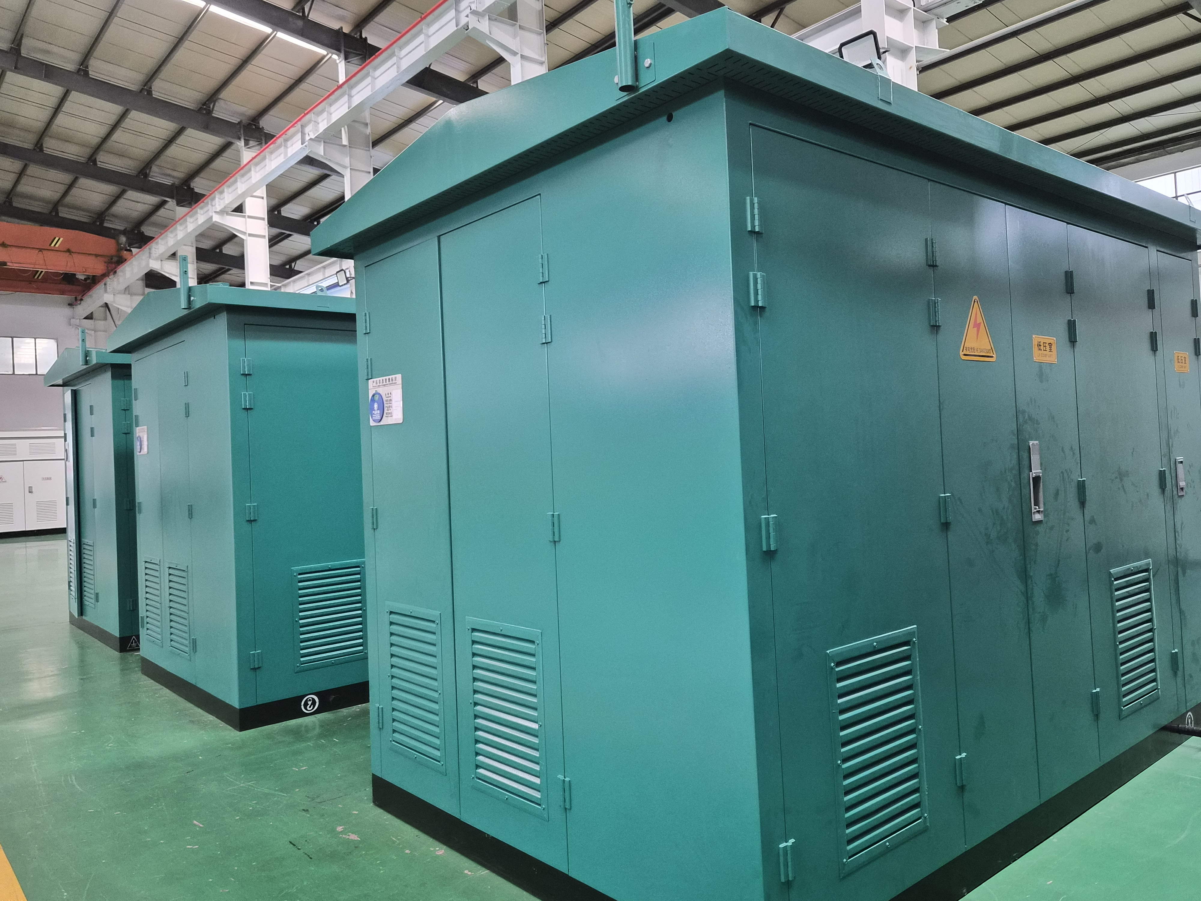
Prefabricated cabin substation: switchgear, transformer and auxiliary systems are assembled and tested before the module leaves the factory.
Configuration comparison at a glance
| Configuration | Capacity and voltage | Protection integration | Installation model | Typical fit |
|---|---|---|---|---|
| Single-phase pole-mounted (D-M) | 5–167 kVA single-phase; ONAN; −40 to +40 °C; up to 2,000 m | Sealed tank and bushings only; switching and fusing handled by line equipment on the pole | Pole mounting with side brackets; no distribution room | Rural grids, scattered villages, irrigation, temporary or emergency supply |
| Single-phase pad-mounted (ZGD-H/ZGD-Z) | 15–250 kVA; 120/240 V centre-tapped LV; amorphous or silicon-steel core | Enclosed HV elbow bushings and LV compartment; tamper-resistant ground-level enclosure | Concrete pad, ground-level setting, cable terminations | North American residential distribution, retail, street lighting |
| Three-phase pad-mounted (ZGS-H/ZGS-Z) | 75–2,500 kVA; 4.16–34.5 kV HV; 240/480/600/347 V LV; DOE 2016 / CSA 2023 efficiency | Internal load-break switch, fuse and surge arrester; fully insulated elbow connectors; loop or radial feed | Concrete pad; cable or busbar terminations; compact footprint | Commercial complexes, industrial parks, municipal utilities, distribution-side renewables |
| Prefabricated cabin (YBM/ZGS11/ZGS13) | 10/35 kV; 500–50,000 kVA; IP54/IP55; −40 to +50 °C | HV switchgear, transformer, LV switchgear, compensation, automation, AC/DC, environmental control, monitoring | Factory pre-assembly and test; transport as a complete unit; crane lifting; site connection | PV, wind and storage step-up, data centres, industrial plants, remote or infrastructure-limited projects |
Capacity, protection and installation data as published in the product specifications of the corresponding series.
Site constraints that eliminate options early
Space, access and grid interface
The first filter is not electrical. A pole-mounted unit assumes an overhead line and a pole asset that can carry the transformer; where distribution is underground by design or by municipal requirement, that option closes immediately. A pad-mounted unit assumes ground-level space that the public can reach without a fenced substation, which is precisely why the enclosure is tamper-resistant, and it needs a concrete pad plus the clearances the local utility specifies. A prefabricated cabin assumes a transport route that accepts the module dimensions and a crane that can lift it — the specification explicitly allows standard container dimensions and customisable cabin sizes, and states that installation is transport as a complete unit plus crane lifting and on-site connection.
Climate, altitude and corrosion
Environmental ratings differ across the three configurations, and the difference is easy to miss at quotation stage. The pole-mounted range is stated for −40 °C to +40 °C and elevations up to 2,000 m; above that elevation a derating or redesign conversation is required. The cabin range is stated for −40 °C to +50 °C with IP54/IP55 protection, rock-wool insulation, industrial air conditioning, forced ventilation and heating, and optional fire protection — a design intended for high altitude, high humidity, dust and salt-spray environments. Pad-mounted units address the same problem through enclosure finish: military green or gray anti-corrosion powder coating, with stainless-steel or carbon-steel welded tanks for coastal, humid and high-temperature sites.
Load size and phase
Capacity ceilings do most of the remaining filtering. Single-phase pole-mounted ends at 167 kVA. Single-phase pad-mounted ends at 250 kVA. Three-phase pad-mounted reaches 2,500 kVA. Above that, or where several pieces of equipment must be coordinated on one structural base, the prefabricated cabin takes over from 500 kVA and extends to 50,000 kVA. A project that begins with a 100 kVA single-phase load and a five-year growth plan should be modelled against the next step, not the first.
Protection integration: what actually sits inside the enclosure
Protection scope is the clearest functional difference between the configurations, and the one that most affects operations afterwards.
On a pole-mounted unit the transformer is a sealed tank with bushings, a drain valve, an oil-level gauge, a grounding terminal and a nameplate. Switching, fusing and surge protection sit in the line equipment on the pole rather than in an integrated enclosure. The practical consequence is that fault clearance or fuse replacement is line work at height, and there is no ground-level operating interface.
On a pad-mounted unit the protection is inside the enclosure: the three-phase series lists an internal load-break switch, fuse and surge arrester, with loop-feed configuration optional; the HV bushings are epoxy-resin moulded with elbow connectors, described as fully insulated and sealed for protection against accidental contact. This is what allows the unit to stand in a publicly accessible area without a fence, and it concentrates operation, isolation and fault clearance at ground level.
On a prefabricated cabin the enclosure holds an entire protection and control scope: metal-clad withdrawable or fixed HV switchgear with vacuum circuit breakers, LV switchgear, compensation equipment, an integrated automation system with temperature, humidity, smoke, water-ingress and access monitoring, AC/DC supply, HVAC and optional gas or ultra-fine dry-powder fire protection. The trade-off is that the auxiliary systems need a reliable station service supply and a defined maintenance routine of their own — the cabin is a small substation, not a large transformer.
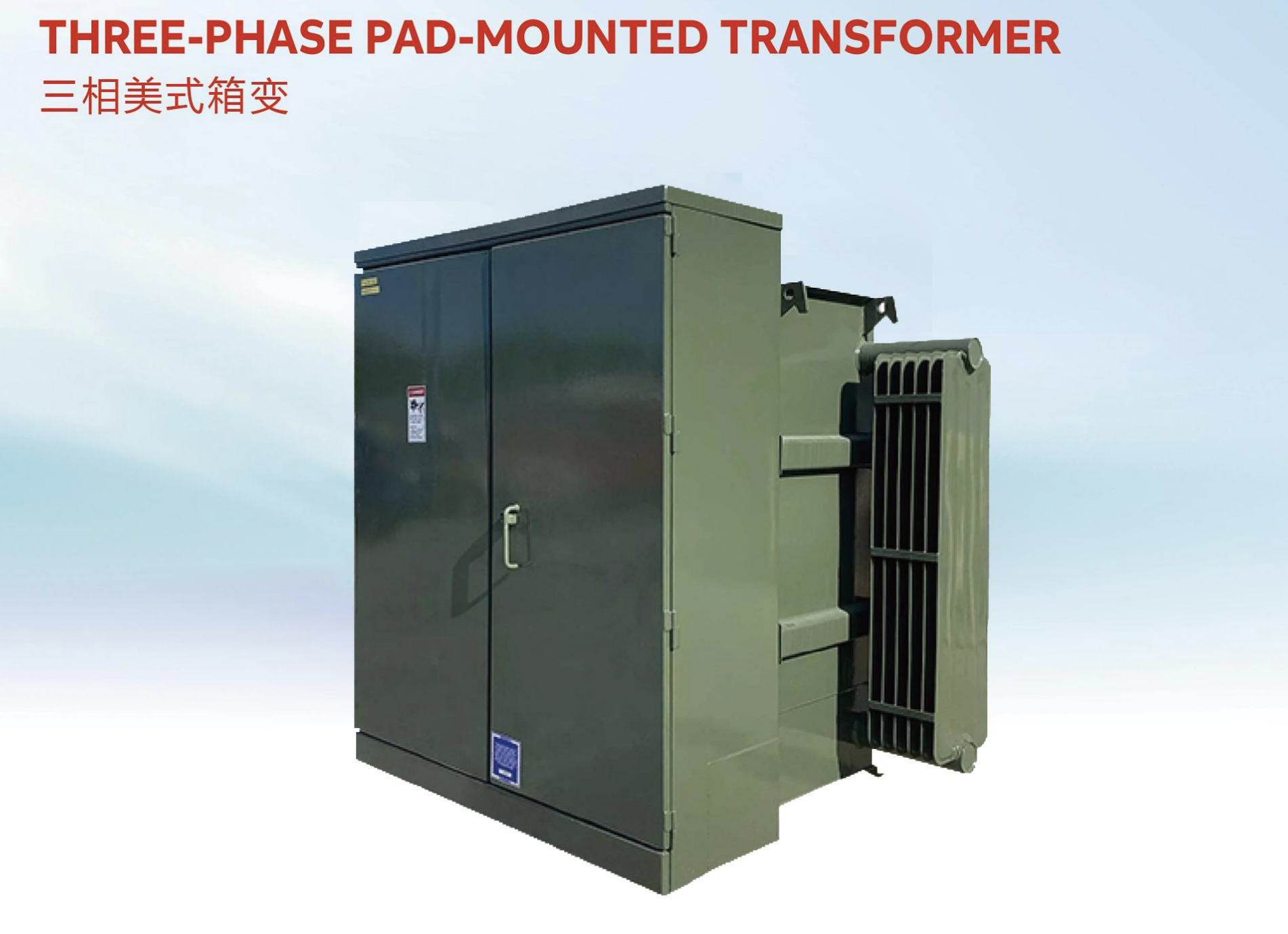
Three-phase pad-mounted transformer: switching, fusing and surge protection are integrated into the ground-level enclosure.
Installation models and what they do to the schedule
Pole mounting is the lightest site model: no distribution room, no pad, and according to the product data a reduction in civil cost and low-voltage line losses of more than 60%. It trades that simplicity for an overhead line dependency and for maintenance at height.
Pad mounting moves work into civil scope: a concrete pad, a defined footprint, cable or busbar terminations and the utility's clearance requirements. In exchange the unit is operable from ground level and, in the three-phase version, can be configured for loop or radial feed to suit the network layout.
The prefabricated cabin moves work in the opposite direction — into the factory. Assembly, wiring, factory pre-assembly and full-load testing happen before shipment, then the module is transported complete and lifted into position. For overseas projects in areas with limited transport access, or for renewable-energy and data-centre projects where site labour is scarce, that shift is the main reason the configuration is selected.
Schedule expectations differ accordingly and should be built into the programme rather than discovered at the kick-off meeting. Typical figures published by the supplier are 30–60 days for standard distribution transformers and 45–75 days for customised units, 60–90 days for standard new-energy transformers, and 90–120 days for prefabricated cabin substations, all subject to technical evaluation and the technical agreement. Order quantity is not the constraint: minimum order quantity is one unit for transformers and one cabin for substations, with project-based scheduling.
Matching configuration to project type
- North American residential and rural distribution. Single-phase pole-mounted or pad-mounted units at 60 Hz, with ANSI/IEEE compliance, UL/CSA certification, and HV classes of 34.5, 13.8, 13.2 or 12.47 kV. Pad-mounted single-phase units deliver 120/240 V centre-tapped supply for homes, retail and street lighting.
- Commercial complexes, industrial parks and municipal utilities. Three-phase pad-mounted units from 75 to 2,500 kVA, where integrated switching and a compact footprint matter more than an enclosed building.
- PV, wind and energy-storage plants. Prefabricated cabin substations at 10/35 kV, with the transformer, switchgear, compensation and automation integrated on one base; the same configuration applies to step-up substations for renewable plants and to energy-storage interconnections.
- Data centres and AI computing parks. Dry-type transformers for indoor MV/LV distribution, with a prefabricated cabin or oil-immersed unit for the incoming supply where capacity and outdoor space allow.
- Mines, oil and gas fields, and overseas EPC projects with limited infrastructure. Prefabricated cabin substations, because the site work is reduced to lifting and connecting rather than building.
Where each configuration is a poor fit
A comparison that lists only advantages is not usable for procurement. The boundaries matter more than the benefits.
- Pole-mounted is a poor fit above 167 kVA, for three-phase loads, or anywhere distribution is underground. It also shifts maintenance to height: fuse or switch operations are line work, and there is no enclosed operating interface at ground level.
- Pad-mounted is a poor fit where ground-level public space is unavailable or where the utility requires an enclosed station. A second, less obvious boundary is certification: these units are built to ANSI/IEEE with UL/CSA certification and North American LV voltages such as 120/240 V at 60 Hz. A unit engineered for an IEC 50 Hz market is not interchangeable with one built for a North American utility, even at the same kVA — the vector group, voltage class, efficiency basis and certification file all change.
- Prefabricated cabin is a poor fit for small dispersed loads. It carries the longest lead time of the three at 90–120 days, requires crane access and a transport route that accepts the module, needs a foundation and cable connection scope, and depends on station service power for its HVAC and monitoring. Applying it to a single 100 kVA load over-specifies the project.
- Indoor and fire-sensitive locations change the insulation decision, not the enclosure decision. Where oil-free, flame-retardant and low-noise installation is required — underground spaces, high-rise buildings, hospitals — the transformer itself is specified as cast-resin dry-type, and the deployment question becomes how that unit is housed rather than which outdoor enclosure is chosen.
What a supply partner adds to a custom deployment
Apex Power Systems (Nanjing) Co., Ltd. is a Nanjing-based international trading and supply-partner company that sources power transformers, box-type substations and complete substation equipment from audited Chinese manufacturers for utility, EPC and industrial buyers. It is not a factory; manufacturing, certification and test evidence belong to its audited manufacturing partners, and Apex manages selection, supervision, documentation and delivery on the buyer's behalf.
That positioning matters specifically in a deployment decision, because the three configurations usually sit with different manufacturers. A partner can compare a pole-mounted, a pad-mounted and a cabin quotation against the same site constraints and the same protection scope, and can challenge a specification that over-reaches — a cabin proposed for a load that a three-phase pad-mounted unit would serve, or a pad-mounted unit proposed for a site that has no pad space.
The verification scope covers factory audit before commitment, certification checking in the correct legal entity and for the exact product family — ISO 9001, ISO 14001 and ISO 45001 management systems, IEC conformity for 10 kV/35 kV transformers and box-type substations, UL and CSA product certification, CQC certification for box-type substations and switchgear, and independent type testing including a KEMA Labs Type I Inspection Report for a 250 MVA / 345 kV transformer — plus pre-shipment factory acceptance testing, optional third-party inspection, and joint site acceptance testing with the customer after installation.
Customisation relevant to deployment includes IP54/IP55 protection ratings, C3/C4/C5 anti-corrosion finishes, high-altitude derating, seismic design, noise reduction and custom voltage ratios, capacities, impedances, vector groups and tap ranges, with a technical proposal typically returned in 3–5 business days and a design cycle of 15–30 days depending on complexity. Delivery references co-managed through the partner network include a 15 MVA pad-mounted transformer project for a North American transmission company, a 40,000 kVA energy-storage project in Bulgaria, a 110 kV substation equipment supply in Mongolia, and a commercial development project in Panglao, Philippines delivered with engineering and installation guidance.
Market direction: efficiency rules and prefabrication
Two regulatory signals are shaping what gets specified inside whichever enclosure is chosen. China's GB 20052-2024, the minimum allowable values of energy efficiency and energy efficiency grades for power transformers, took effect on 1 February 2025. In the United States, the Department of Energy's 2024 rule under 10 CFR Part 431 requires distribution transformers to transition towards amorphous electrical steel starting in 2029. Neither rule dictates pole, pad or cabin, but both push loss performance into the specification — which is where amorphous-alloy core options, already offered in the pole-mounted and single-phase pad-mounted ranges with stated no-load loss reductions of 60–80% against conventional silicon-steel cores, become a commercial rather than a technical question.
The second direction is prefabrication. As renewable-energy and data-centre projects compress construction schedules, moving assembly, wiring and testing from site into a factory becomes a schedule strategy rather than a preference. That favours cabin configurations on new-build projects, and favours modular expansion on existing ones: capacity upgrades are described as requiring additional cabins rather than rebuilding the station. A reasonable expectation for the near term is not that one configuration displaces the others, but that the deployment decision is documented earlier and with more rigour, because it now commits a project to certification scope, site works and a lead time that no later specification change can recover.
FAQ
How should a buyer decide between pole-mounted, pad-mounted and prefabricated cabin configurations?
Decide in the order that constraints actually bind: first the grid interface and site access, then load size and phase, then protection scope, then schedule. An overhead line with a single-phase load up to 167 kVA points to pole-mounted. Ground-level public space with integrated switching and a load up to 2,500 kVA three-phase points to pad-mounted. Multiple equipment items, a load from 500 kVA upward, or a remote site with limited construction capacity points to a prefabricated cabin. Only after those four filters should the transformer itself be specified.
What site conditions rule out a pole-mounted transformer?
Three conditions rule it out. The first is load: the range ends at 167 kVA and is single-phase, so three-phase or larger loads cannot be served. The second is the distribution method: pole mounting requires an overhead line and a pole asset, so areas with underground distribution cannot use it. The third is the operating model: the unit is a sealed tank with bushings and mounting brackets, with switching and fusing handled by line equipment, so fault clearance is work at height rather than at a ground-level interface. The published environmental limits are −40 °C to +40 °C and elevations up to 2,000 m.
What protection is integrated into a pad-mounted transformer compared with a pole-mounted unit?
A pad-mounted transformer encloses high-voltage and low-voltage switching, fusing and protection together with the transformer in a tamper-resistant steel enclosure at ground level on a concrete pad. In the three-phase range this includes an internal load-break switch, fuse and surge arrester, with epoxy-resin moulded HV bushings and elbow connectors that are fully insulated and sealed, and an optional loop-feed configuration. A pole-mounted unit has no such enclosure: it is a sealed tank with bushings, a drain valve, an oil-level gauge, a grounding terminal and a nameplate, and the switching and fusing sit in the line equipment on the pole.
Why does a prefabricated cabin substation take longer to deliver than a pad-mounted transformer?
Because the scope is larger. A pad-mounted unit is a single transformer with integrated switching; a cabin integrates HV switchgear, transformer, LV switchgear, compensation equipment, automation, AC/DC supply and environmental control, and is assembled, wired and tested as a complete substation before shipment. Published lead times reflect that: 30–60 days for standard distribution transformers and 45–75 days for customised units, against 90–120 days for prefabricated cabin substations, subject to technical evaluation and the technical agreement. The trade-off is that site work reduces to crane lifting and connection.
Can a transformer certified for one market be redeployed in another?
Not automatically. Certification is specific to a product family, a standard basis and a market. Pad-mounted units in this range are built to ANSI/IEEE with UL/CSA certification and North American low-voltage configurations such as 120/240 V at 60 Hz and high-voltage classes of 34.5, 13.8, 13.2 or 12.47 kV. IEC conformity applies separately to 10 kV/35 kV power transformers and box-type substations. Frequency, voltage class, vector group and efficiency basis all change with the destination market, so the correct check is the certificate, its issuing body and the exact product family it covers — not the kVA rating.
Product specifications, capacities and lead times referenced above are published by the manufacturer and are subject to technical evaluation for each project. The Apex Power Systems catalogue, including transformer and substation ranges, can be downloaded here: Apex Power Systems Catalog (PDF).
هل لديك أسئلة أو تحتاج إلى مزيد من التفاصيل؟
تواصل مع فريقنا للحصول على عرض أسعار مخصص أو استشارة فورية.
طلب عرض أسعار
املأ النموذج أدناه وسيتواصل معك فريقنا بعرض مقترح مخصص.
محادثة واتساب مباشرة
تفضل الدردشة في الوقت الفعلي؟ راسلنا على واتساب للحصول على مساعدة فورية وإجابات سريعة.
- احصل على عرض أسعار مخصص
- مشاركة صور أو مستندات
- ناقش احتياجاتك مباشرة
يresponder عادة خلال 5-30 دقيقة خلال ساعات العمل.