
Custom Transformer Field FAQ: Noise, Oil Leaks, Overheating
A transformer that hums louder than it used to, weeps a little oil, or runs hotter than its nameplate suggests is usually reporting an operating condition rather than announcing a failure. The difficulty for a plant engineer or a procurement team is that the same three symptoms — abnormal noise or vibration, oil leakage and abnormally high oil temperature — can each be caused by something external, something correctable on site, or something internal that requires the unit to come out of service. This field FAQ sets out the safe first checks, the probable causes, and the point at which a custom transformer problem should be documented and escalated to the supplier under the agreed acceptance criteria or warranty.
Apex Power Systems (Nanjing) Co., Ltd. is an international trading and supply partner for power transformers, box-type substations and complete substation equipment, based in Nanjing, Jiangsu Province, China. It is not a factory: it selects, audits and manages a network of verified manufacturing partners on behalf of overseas utility, EPC and industrial customers, and manages design review, witness testing, documentation, freight and commissioning on the customer's behalf. The field guidance below applies to oil-immersed and dry-type custom transformers generally, and the product references are drawn from the ranges supplied through that partner network.
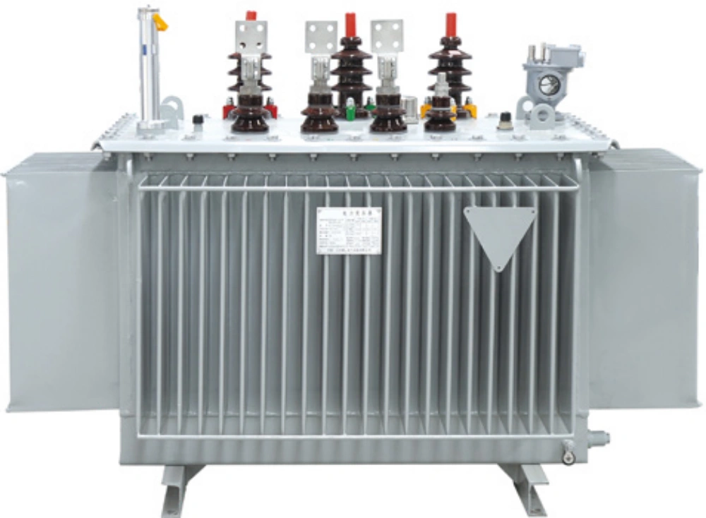
Oil-immersed distribution transformers are the units most often involved in field complaints about noise, leakage and oil temperature.
Why these three symptoms need a structured response
A field complaint about noise, oil or temperature is hard to resolve because the symptom is an effect, not a cause. Noise can originate in the core, in the windings, in a cooling fan, in the mounting structure, or in the supply itself. Oil can escape from a gasket, a flange, a valve, a weld or a bushing turret, and the leak point is often not where the oil appears. High oil temperature can be genuine overload, a cooling-system failure, a low oil level, an incorrect reading, or an internal fault such as a shorted turn. Because the causes span external, mechanical, thermal and internal categories, a fixed sequence — classify, record, eliminate external causes, then test — protects both the equipment and the warranty position.
Isolate and earth before any physical inspection
The first check is not a measurement, it is a control. Any inspection inside an enclosure, and any work on a bushing turret, valve or radiator joint, must be carried out with the transformer isolated, locked out and earthed, with a check that no residual charge remains before any terminal is touched. A transformer tank or bushing turret must never be opened while the unit is energised. Where oil is being handled, fire precautions and spill containment belong in the method statement, and high-voltage tests should be performed only by qualified personnel using calibrated test equipment.
Everything that can be established without touching the unit should be recorded first: load current, ambient temperature, the temperature reading and its relationship to the rated temperature rise, whether the noise is continuous, intermittent or load-dependent, and the exact location of any oil staining. This record is what separates a symptom that can be trended from a symptom that can only be argued about.
Abnormal noise or vibration: what to check first
Noise has to be classified before it is investigated, because the pattern of the noise points to the cause. Noise that varies with load points to the core, the windings or magnetostriction. Noise that is constant regardless of load often points to loose clamping or a resonance with the mounting structure. Intermittent noise usually points to a fan, a pump or a loose connection. Measuring the harmonic and DC content of the supply early is worthwhile, because harmonic distortion and DC magnetisation from connected loads are common external causes that can be corrected without opening the transformer.
- Identify whether the noise is continuous, intermittent or load-dependent.
- Check the cooling fans and pumps for bearing wear.
- Check the mounting bolts and investigate structural resonance.
- Measure the harmonic content and any DC component in the supply.
- Take an oil sample for dissolved gas analysis and check the core earthing connection.
- If the noise increases with load and the gas analysis is abnormal, de-energise the unit and inspect the core and clamping structure.
Decision rule: a hum that rises with load but matches normal magnetostriction and clean oil test results is an operating characteristic. A load-dependent hum accompanied by abnormal dissolved gas readings is an internal condition that requires the unit to be taken out of service.
Oil leakage: locate the point before adding oil
Oil leakage is a progressive fault rather than a cosmetic one. Beyond the environmental and safety exposure, a falling oil level reduces both insulation and cooling, and a leak that is not repaired will eventually cause an outage or a fire risk. The correct approach is to locate the exact leak point rather than topping up the oil and waiting, because the position of the leak indicates the cause — a gasket, a flange, a weld, a valve or overpressure. If the leak follows significant temperature cycling, or the tank appears over-pressurised, check the breather before touching any seal, since a blocked breather is a common root cause.
Causes to work through: age-hardened or incorrectly seated gaskets; loose flange bolts; weld or casting defects; leaking valves or gland packing; corrosion of the tank or pipework; and overpressure caused by a blocked breather or an incorrect oil level.
- Clean the area and locate the exact leak point — tank, bushing turret, valve or radiator joint.
- Check the breather and the conservator oil level to rule out overpressure.
- For a gasket leak, retighten to the specified torque or replace the gasket.
- For a weld or casting defect, repair under an approved welding procedure and re-test.
- Replenish with the correct oil grade and re-test dielectric strength and moisture.
- Record the leak, cause and repair in the maintenance history.
Two details matter on custom units. First, the oil grade is part of the specification: the oil-immersed distribution range is supplied with No. 25 mineral oil, No. 45 low-temperature oil or FR3 natural ester oil, and topping up with a different grade changes both insulation and cooling behaviour. Second, tank construction determines where leaks appear and how they can be verified — corrugated tanks are used up to 1,600 kVA and tubular radiators from 2,000 kVA, with a fully sealed construction and either a bladder or a conservator as an option.
Boundary condition: this symptom class does not apply to dry-type transformers. The SCB12–SCB18 epoxy resin cast dry-type range contains no insulating oil, which is precisely why it is specified for fire-sensitive indoor locations. On a dry-type unit, a temperature or noise complaint moves the investigation to winding temperature control, cooling fans and enclosure ventilation instead.
Abnormally high oil temperature: three causes, checked in order
An abnormally high oil temperature is nearly always one of three things: the unit is genuinely overloaded, the cooling system is not working, or the temperature is being read incorrectly. The method is to work outwards from the simplest cause — record the load current and ambient temperature first, then check the cooling system, then the oil level, and only then the instrument. If all external causes are eliminated, take an oil sample for dissolved gas analysis, because a sustained high temperature with abnormal gas readings indicates an internal fault and the unit should be de-energised before it fails on its own.
Causes to consider: sustained overload; cooling-system failure such as a fan or pump not running, blocked radiators or closed valves; low oil level; high ambient temperature or blocked ventilation in the room; harmonic content from non-linear load; incorrect thermometer calibration; or an internal fault such as a shorted turn.
- Record load current, ambient temperature and the temperature reading, and compare with the rated temperature rise.
- Check the cooling system — fans, pumps, radiator valves and control circuits.
- Check the oil level and inspect for leaks.
- Verify the thermometer and alarm contacts.
- If no external cause is found, take an oil sample for dissolved gas analysis.
- Reduce load or improve ventilation while investigating.
- If the gas analysis indicates an internal fault, de-energise the unit and carry out an internal inspection before returning it to service.
| Symptom | First checks (unit isolated and earthed) | Evidence to record | Escalation trigger |
|---|---|---|---|
| Abnormal noise or vibration | Classify continuous, intermittent or load-dependent; check fan and pump bearings; check mounting bolts and structural resonance; measure supply harmonics and DC | Noise pattern, load at the time, harmonic and DC measurements, dissolved gas analysis result, core earthing check | Noise increases with load and gas analysis is abnormal — de-energise and inspect core and clamping structure |
| Oil leakage | Clean the area and locate the exact leak point; check the breather and conservator level to rule out overpressure | Leak location with photographs, oil level history, oil grade used for any top-up, dielectric strength and moisture results after top-up | Weld or casting defect, or a repeat leak after correct gasket work |
| Abnormally high oil temperature | Record load current and ambient; check cooling system, radiator valves and oil level; verify thermometer and alarm contacts | Load, ambient and temperature readings against rated rise, cooling stage in service, tap-changer counter, gas analysis result | External causes eliminated and gas analysis indicates an internal fault — de-energise and inspect internally |
Read the cooling class before blaming the load
The cooling class is the code on the nameplate that determines how much load the unit may carry, and it is frequently the answer to an overheating complaint. The code combines two things: the internal cooling medium and how it circulates, and the external cooling medium and how it circulates. O stands for oil and A for air, N for natural circulation and F for forced circulation. An ONAN transformer relies on natural oil circulation and natural air cooling; adding fans (ONAF) raises the permissible loading, which is why the same transformer often carries more than one rating on its nameplate.
A concrete example makes the point. The SFZ-250000/345 three-phase oil-immersed on-load voltage regulating power transformer is rated 250/250 MVA at 345/34.5 kV, 60 Hz, vector group Dyn1, and its cooling stages are declared as ONAN at 185 MVA, ONAF1 at 225 MVA and ODAF2 at 250 MVA. A reading of 200 MVA is therefore within the rating with forced cooling in service and above the natural-cooling rating if the fans are not running. In other words, the first question in an over-temperature investigation is not how hot the oil is, but which cooling stage is actually in service.
The cooling class must also be checked against the ambient temperature and altitude of the installation site. For dry-type units the equivalent constraint is the temperature-rise limit: the SCB12–SCB18 range is quoted with insulation class F (155 °C) or H (180 °C) and temperature-rise limits of F 100 K or H 125 K, with AN natural air or AF forced air cooling and up to 150% rated load under forced-air cooling. It uses PT100 resistance sensors with an intelligent controller providing over-temperature alarm or trip, so on a dry-type unit the alarm may be reporting a winding-temperature condition rather than an oil condition at all.
Oil testing: BDV, moisture and dissolved gas analysis
Oil testing is the most useful single diagnostic because the oil condition reflects the internal state of the transformer. Three tests carry most of the weight in a field dispute. Dielectric strength, reported as breakdown voltage (BDV), indicates whether the oil can still withstand voltage. Moisture content indicates how much water the paper-oil insulation is carrying. Dissolved gas analysis (DGA) indicates whether the oil has been exposed to abnormal thermal or electrical stress.
Moisture matters because water and trapped air destroy the dielectric strength of oil-paper insulation. Cellulose insulation is hygroscopic and absorbs moisture during manufacture, transport and site assembly, while insulating oil holds dissolved gas; both lower the breakdown voltage and can initiate partial discharge, particularly under impulse voltage. This is why the active part is dried and the tank evacuated after assembly, and why filtered hot oil is introduced under vacuum so that the insulation is fully impregnated. It is also why a leak that draws in moist air, or a top-up with the wrong or unprocessed oil, is a dielectric issue and not merely housekeeping.
A workable preventive programme is built around the oil and combines visual inspection, oil testing, breather and cooling-system checks, bushing and connection inspection, and verification of protection devices and the tap-changer counter. Readings should be recorded and trended rather than judged in isolation, because a sudden change in dissolved gas or moisture is the earliest warning of an internal fault.
- Check the oil level and inspect for leaks.
- Sample the oil for dielectric strength (BDV), moisture and dissolved gas analysis (DGA).
- Inspect and replace the silica gel in the breather and check the oil cup.
- Clean the bushings, check connections for overheating with a thermographic scan, and verify torque.
- Operate the tap changer and record the operation counter.
- Verify thermometers, the Buchholz relay, the pressure-relief device and alarms.
- Inspect the cooling system — fans, pumps, radiators — and clean as required.
- Record all readings and compare them with previous trends.
When to escalate to the supplier — and what to send
Escalation is a documentation exercise, not a complaint. A symptom becomes a supplier matter when external causes have been eliminated and the evidence set is complete enough to be checked against the acceptance criteria or the warranty terms of the contract. The record should include the following:
- Load current, ambient temperature and the temperature reading at the time of the event, against the rated temperature rise.
- The character of the noise — continuous, intermittent or load-dependent — and whether it changes with load.
- The exact leak location, with photographs, and the oil level history.
- Oil test results: BDV, moisture and DGA, with sampling dates.
- The tap-changer operation counter and tap position history.
- Protection and alarm events, including over-temperature alarms and Buchholz or pressure-relief operation.
- Harmonic and DC measurements taken on the supply where noise or temperature is the complaint.
With that set in hand, the supplier can be asked for a technical position under the contract rather than an opinion. In Apex-coordinated projects, quality control is structured around a pre-shipment factory acceptance test and a joint site acceptance test with the customer after installation, with third-party inspection available on request, so the baseline performance of the unit — ratio, resistance, no-load and load losses, impedance, insulation and oil quality — is already documented before the unit leaves the works. That baseline is what a field symptom is compared against.
Warranty handling is contract-specific: the distribution transformer range is quoted with a 12-month warranty, while large power transformer and prefabricated cabin substation projects are quoted with 12 to 24 months per contract, supported by spare parts supply, remote technical support and optional on-site commissioning. The practical rule is simple — report the symptom with evidence while the unit is still in service, because an oil sample taken after the unit has been de-energised for a long period is a much weaker record than one taken when the symptom appeared.
Baseline test records established before shipment are what a later field symptom is measured against.
Where these symptoms are most likely to appear
The application determines which of the three symptoms is most probable, and it also determines which checks are meaningful.
- Distribution and substation networks. The S13/S14/S15 range covers 30–3,150 kVA at the 10 kV class and 3,150–31,500 kVA at the 35 kV class, ONAN cooled, with corrugated tanks up to 1,600 kVA and tubular radiators from 2,000 kVA. Outdoor units that cycle in temperature are where gasket and radiator-joint leaks and breather-related overpressure appear.
- Renewable energy blocks. The SC10/SZ18/SZ20 range for PV, wind and storage covers 500–12,500 kVA at 10 kV and 1,000–12,500 kVA at 35 kV, with impedance options from 6.0% to 14.0%, and is specified with temperature and oil-level monitoring, a pressure relief valve and a Buchholz relay. Inverter-fed blocks are where harmonic and DC-bias resistance is a stated requirement, so a noise complaint should be checked against supply harmonics before the transformer is opened.
- Data centres, commercial buildings and indoor substations. These use dry-type and prefabricated solutions. A dry-type unit in a fire-sensitive location will not leak oil; complaints relate to winding temperature, cooling fans and enclosure ventilation, with the intelligent controller and PT100 sensors providing alarm and trip signals. Where a site must be energised quickly, a prefabricated cabin substation is assembled, tested and commissioned at the factory before transport in modules for site connection.
- Industrial and mining loads. The mining range uses an H-class insulation system and is designed for high humidity, heavy dust and strong vibration with flameproof construction. Under those conditions, vibration-related loosening and cooling-path blockage are more likely explanations for noise and temperature than an electrical fault, so the mechanical checks come first.
Trend-based maintenance versus run-to-failure
The traditional alternative to the sequence above is reactive maintenance: run the unit until an alarm or a failure forces action, then repair. That approach needs no test programme, but it discards the information that makes a diagnosis cheap. A single dissolved gas reading taken after a fault is far less useful than a series of readings showing when the trend changed, and the difference between a planned outage and a forced one is usually visible in the data months earlier.
The limits of the diagnostic approach should be stated honestly. An oil test identifies the type of mechanism at work, not always its location: a DGA result consistent with a thermal fault does not by itself identify which winding, connection or core region is generating the heat, and confirming the location generally requires de-energisation and internal inspection, which may not fit inside a planned outage window. On a fully sealed transformer, the oil level cannot be verified visually, so a slowly falling level may only be detected through pressure behaviour or by finding the leak. Replacing a gasket without correcting the pressure condition that caused the leak will produce a repeat leak. And a load-dependent hum is not proof of an internal fault — normal magnetostriction rises with load, and the decision to open a unit should follow oil test results, not the sound alone.
Market and regulatory context
Two regulatory developments are pushing transformer design in directions that change how these symptoms present. China's GB 20052-2024, Minimum allowable values of energy efficiency and energy efficiency grades for power transformers, took effect on 1 February 2025 and sets the efficiency grading that new units must meet in that market; the S13/S14/S15 distribution range is quoted at Grade 1 or Grade 2 in accordance with GB 20052. In the United States, the Department of Energy 2024 rule under 10 CFR Part 431 requires distribution transformers to transition towards amorphous electrical steel starting in 2029, which shifts the loss profile of new units towards lower no-load losses.
The load itself is changing at the same time. The U.S. data centre substation market was valued at USD 3.44 billion in 2024, driven by AI and cloud computing growth, and non-linear, harmonic-rich loads are increasingly part of the picture in commercial and data-centre distribution. That combination — higher efficiency expectations on the equipment and more distorted loads on the supply — is the reason harmonic and DC measurement belongs in the first round of checks for a noise or temperature complaint rather than in the last.
Future outlook
Condition-based maintenance is moving from a specialist practice to a standard expectation, because the monitoring hardware is already being specified into new transformers. The new energy transformer range, for example, includes temperature and oil-level monitoring, a pressure relief valve and a Buchholz relay, and is offered with online oil dissolved-gas monitoring and remote communication interfaces as part of its smart integration package. Once oil condition data is available remotely, the escalation decision described in this article changes character: instead of a maintenance team discovering a trend during a routine visit, the trend itself triggers the oil sample request, the spare-parts order and the warranty notification.
The same shift applies to prefabricated and containerised substations, where integrated automation already covers temperature, humidity, smoke, water ingress and access monitoring. For a custom transformer, the practical implication is that the technical specification agreed at the enquiry stage — cooling class, temperature-rise limits, oil grade, monitoring package and test regime — increasingly determines what can be diagnosed remotely and what will still require an engineer on site. Buyers who treat those line items as commercial detail rather than engineering constraints usually discover their value at the first field complaint.
Frequently asked questions
What do ONAN and ONAF mean on a transformer nameplate?
The cooling class is a four-letter code describing how a transformer is cooled, indicating the internal cooling medium and its circulation together with the external cooling medium and its circulation. O means oil and A means air; N means natural circulation and F means forced circulation. ONAN therefore describes an oil-immersed unit with natural oil circulation and natural air circulation, while ONAF adds fans that force air over the radiators and raises the permissible loading. The code defines the rated capacity of each cooling stage and the associated temperature limits, and it should be checked against the ambient temperature and altitude of the installation site.
How can an operator tell whether abnormal transformer noise is load-related or mechanical?
The pattern of the noise is the first indicator. Noise that varies with load points to the core, the windings or magnetostriction; noise that is constant regardless of load often points to loose clamping or resonance with the mounting structure; intermittent noise usually points to a fan, a pump or a loose connection. Confirm the pattern, check cooling fans and pumps for bearing wear, check mounting bolts and structural resonance, and measure the harmonic and DC content of the supply. If the noise increases with load and dissolved gas analysis is abnormal, the unit should be de-energised for inspection of the core and clamping structure.
Why must a transformer be isolated and earthed before any inspection?
Isolation, lock-out and earthing are preconditions for any work inside an enclosure or on a bushing turret, valve or radiator joint, and no transformer tank or bushing turret should be opened while the unit is energised. Checking that no residual charge remains before a terminal is touched, using calibrated high-voltage test equipment operated by qualified personnel, and applying fire precautions with spill containment during oil handling are all part of the same control set. Only information that can be gathered without opening the unit — load current, ambient temperature, temperature reading, noise pattern and leak location — should be collected before the unit is taken out of service.
Which oil tests should be requested, and what does each one show?
Three tests cover most of the diagnostic ground. Dielectric strength, reported as breakdown voltage (BDV), indicates whether the oil can still withstand voltage. Moisture content indicates how much water the paper-oil insulation is carrying, which matters because water and trapped air reduce dielectric strength and can initiate partial discharge. Dissolved gas analysis (DGA) indicates whether the oil has been exposed to abnormal thermal or electrical stress. Readings should be recorded and trended rather than judged in isolation, since a sudden change in gas or moisture content is the earliest warning of an internal fault.
When does an oil leak become an acceptance or warranty matter rather than routine maintenance?
A leak becomes a documented matter when it can be traced to a source that maintenance cannot correct — a weld or casting defect rather than a gasket, for example — or when it recurs after correct retightening or gasket replacement, which usually indicates an underlying pressure condition such as a blocked breather. The record should include the exact leak location with photographs, the oil level history, and the oil test results after any top-up, including dielectric strength and moisture. That package allows the finding to be assessed against the acceptance criteria and warranty terms of the contract rather than treated as an isolated repair.
Can a high oil temperature be an instrument problem rather than an overload?
Yes, and the investigation is deliberately ordered to separate the two. Load current, ambient temperature and the temperature reading are recorded first and compared with the rated temperature rise; the cooling system, oil level and radiator valves are checked next; the thermometer and alarm contacts are verified after that. Only when external causes are eliminated should an oil sample be taken for dissolved gas analysis. If that analysis indicates an internal fault, the unit should be de-energised and internally inspected before it is returned to service.
Reference documentation on the transformer and substation ranges discussed here, including cooling configurations and testing scope, is available in the Apex Power Systems catalogue.