
Custom Transformer Scenario Fit for Solar and Wind Projects
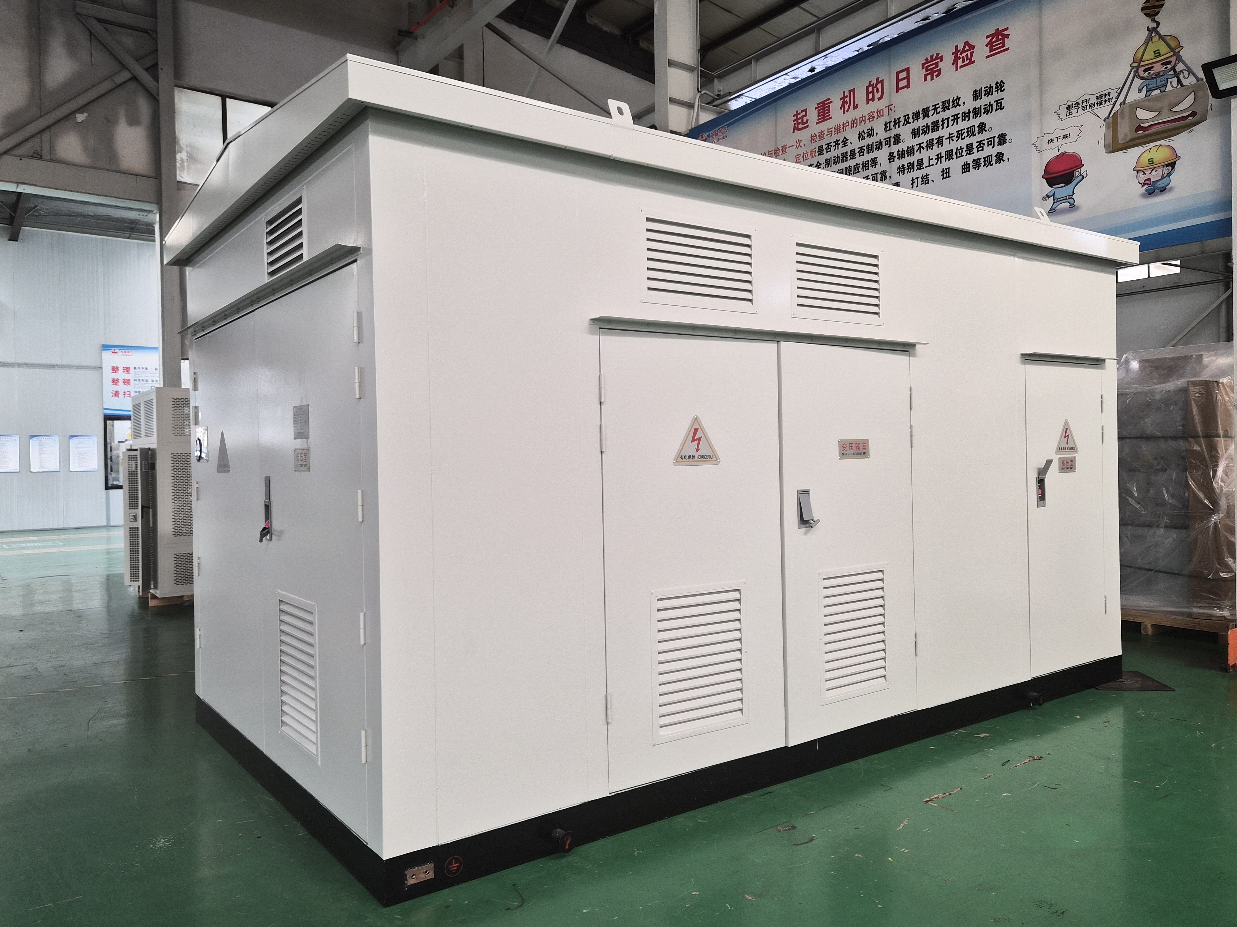
A prefabricated cabin substation integrates high-voltage switchgear, transformer, low-voltage switchgear and auxiliary systems into one factory-assembled module for remote generation sites.
Solar, wind and storage sites rarely fail on transformer quality alone. They fail on scenario fit — the wrong insulation medium at the wrong level of the plant, a cooling class that cannot carry the site's ambient temperature, or a certificate that names a different product family from the one being bought.
The global transformer market is estimated to reach USD 80.8 billion in 2026, and the distribution transformer segment is projected to grow from USD 26.0 billion in 2026 to USD 47.7 billion by 2033 at a compound annual growth rate of 9.1%. Within that, the box-type substation market for photovoltaics is estimated at USD 4.54 billion in 2026. Global trade in electrical transformers above 500 kVA (HS 850434) reached USD 2.5 billion in 2024, a 12.7% increase year on year. Those figures describe volume; they do not describe the decision a project engineer actually has to make — which family of custom transformer belongs at which level of a generation site, and on what basis that choice is defensible to an owner's engineer.
This reference maps the five transformer families supplied through Apex Power Systems (Nanjing)Co., Ltd. — New Energy Transformer, Energy-Saving Transformer, Dry-Type Transformer, Oil-Immersed Distribution Transformer and the Prefabricated Cabin Substation — onto the collector, distribution and step-up roles found in solar, wind and storage projects. Apex Power Systems (Nanjing)Co., Ltd. is an international trading and supply-partner company based in Nanjing, China, specialising in power transformers, box-type substations and complete substation solutions, and it manages factory selection, factory auditing, testing, documentation and delivery on behalf of overseas utility, EPC and industrial customers. The manufacturing, certification and test evidence referenced below belongs to its audited manufacturing partners.
Why scenario fit — not catalogue rating — decides the specification
A catalogue rating tells you what a transformer can carry. It does not tell you whether the unit will survive the site. Four scenario variables change the answer before any kVA figure is discussed.
What feeds the transformer. At collector level the unit is fed by inverters, not by a stiff utility bus. Inverter output brings harmonic content and DC bias into the magnetic circuit, and different inverter brands do not present the same low-voltage characteristics. The New Energy Transformer is built around a wide-range 0.4–1.14 kV low-voltage winding specifically so that inverters from different brands can be matched without redesigning the winding, and low-loss grain-oriented silicon steel or amorphous alloy is used for the core.
What the grid can deliver into a fault. Impedance voltage is not a nameplate formality on a renewable site; it is the lever that matches the transformer to the system short-circuit capacity. The New Energy Transformer is offered with impedance voltage from 6.0% to 14.0%, with off-circuit tap changing of ±2×2.5% or ±5%, vector groups Dyn11 or Yd11, and capacities of 500–12,500 kVA at 10 kV class or 1,000–12,500 kVA at 35 kV class.
Where the unit physically stands. A container cabin on a desert site, an oil-filled tank on a coastal platform, and a cast-resin unit inside a building are three different thermal and environmental problems, and the corpus of available products answers them with different families rather than different options on one family.
Which certificate the destination market accepts. A technically correct transformer without the certificate of the right product family for that market will not be energised. That constraint is dealt with later in this article because it frequently reverses an otherwise sensible technical choice.
The five families and the renewable energy roles they cover
Understanding scenario fit starts with separating the roles. A generation site needs inverter step-up, station auxiliary and distribution supply, and grid-side step-up — and those are not the same transformer.
| Family | Model range | Capacity and voltage | Renewable-energy role |
|---|---|---|---|
| New Energy Transformer | SC10 / SZ18 / SZ20 | 500–12,500 kVA (10 kV class); 1,000–12,500 kVA (35 kV class); HV 10 / 10.5 / 11 / 35 / 38.5 kV; LV 0.4 / 0.69 / 0.4–1.14 kV | Inverter output step-up and collector transformation in PV, wind and storage plants |
| Energy-Saving Transformer | S(B)H15(21–25)-M | Oil-immersed 30–2,500 kVA; dry-type 500–2,500 kVA; HV 6 / 10 / 10.5 / 11 / 20 / 35 kV | Distribution side of renewable-energy plants and loss-sensitive auxiliary supply |
| Dry-Type Transformer | SCB12–SCB18 | 30–2,500 kVA (10 kV class); 800–25,000 kVA (35 kV class); HV 6–35 kV; LV 0.4–10.5 kV | Step-up and station supply where oil-free, flame-retardant construction is required |
| Oil-Immersed Distribution Transformer | S13 / S14 / S15 | 30–3,150 kVA (10 kV class); 3,150–31,500 kVA (35 kV class); HV 6 / 10 / 10.5 / 11 / 35 kV | Outdoor distribution and transformer packages for renewable substations |
| Prefabricated Cabin Substation | YBM / ZGS11 / ZGS13 | 10 / 35 kV; transformer capacity 500–50,000 kVA; IP54 / IP55; –40 °C to +50 °C | Complete step-up station for PV, wind and energy-storage plants, including remote sites |
The table matters less as a product list than as a dividing line. The first four families are transformers that a project buys into an existing or conventionally built station. The fifth is a station that arrives already assembled, and that distinction changes construction sequencing, not just equipment selection.
Collector level versus step-up level: where each family belongs
At collector level, the transformer steps inverter output up to the medium-voltage collection network. The governing requirements are wide low-voltage compatibility, tolerance of harmonic and DC content, correct impedance for the local fault level, and low losses because these units run loaded for the life of the plant. The New Energy Transformer is designed for exactly this role, and the low-loss design is intended to improve overall plant yield. Configurations are available as oil-immersed, dry-type or prefabricated cabin depending on site and climate.
At distribution and auxiliary level, the transformer supplies station loads, buildings, tracking systems and control equipment. Here the Energy-Saving Transformer with an amorphous alloy core is the loss-driven choice: no-load losses are 60–80% lower than conventional silicon-steel transformers, and efficiency is above the highest national efficiency grade. The Oil-Immersed Distribution Transformer with S13 / S14 / S15 efficiency options complements it where outdoor distribution capacity is the priority, with no-load current reduced by 60–80% and average no-load losses reduced by 25–35% against conventional units, and a fully sealed tank that keeps the oil out of contact with air.
At step-up level, the plant connects to the transmission network and the equipment class changes. Capacities and voltages move into the power transformer range — up to 250 MVA and 345 kV in the reference portfolio, with ONAN / ONAF1 / ODAF2 cooling stages, on-load tap changing and paper-oil insulation, verified by a KEMA Labs Type I Inspection Report for a 250 MVA / 345 kV unit tested to IEC 60076-1/-2/-3, IEC 60076-10 and IEC 60076-11, and to IEEE Std C57.12.00 / C57.12.90.
The practical rule for a buyer is this: if the unit is being selected for inverter compatibility and plant yield, it belongs to the new energy family; if it is being selected for standby loss and long-term energy cost, it belongs to the energy-saving family; if it is being selected for grid-side voltage control, it belongs to the power transformer class.
Dry-type or oil-immersed at collector and step-up level
The insulation medium decides more than fire risk. It decides where the unit can stand, how much it can carry under overload, how much maintenance it needs, and which certifications apply.
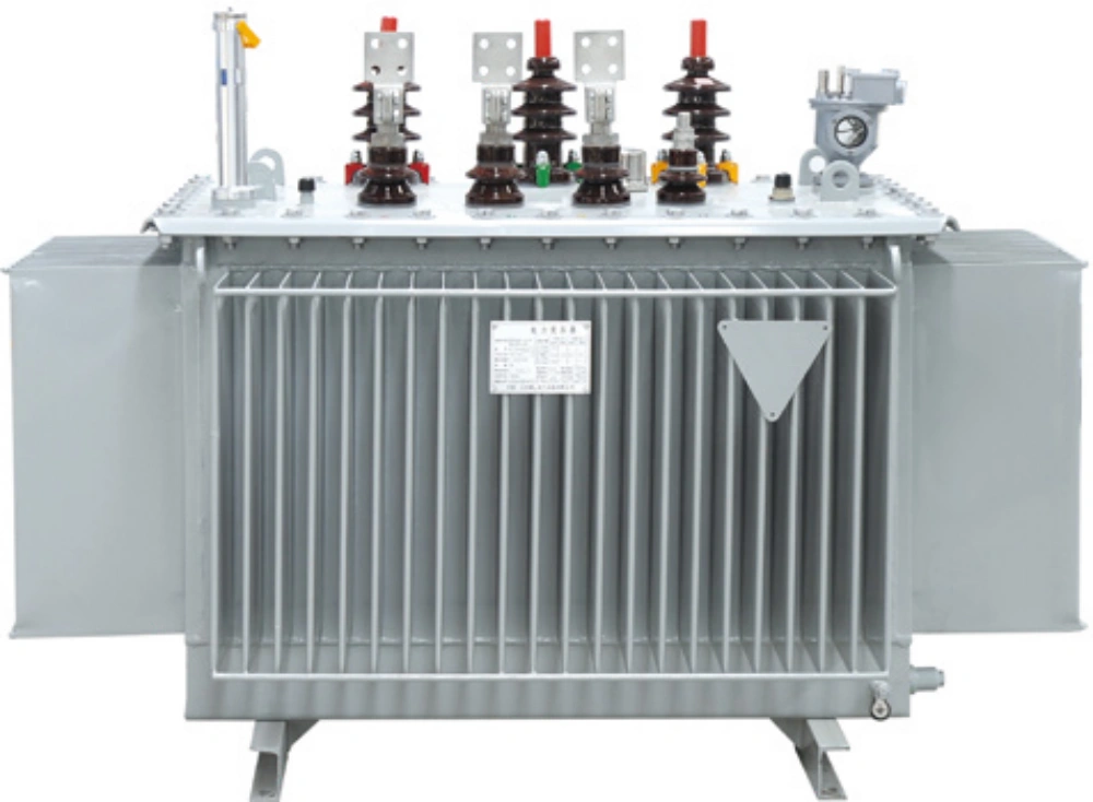
Oil-immersed distribution transformers use a fully sealed corrugated or radiator tank and are specified for outdoor collector and distribution duty.
| Decision criterion | Dry-type (SCB12–SCB18, cast resin) | Oil-immersed (S13 / S14 / S15) |
|---|---|---|
| Location and fire exposure | No insulating oil; flame-retardant and explosion-resistant; can be installed close to the load | Contains insulating oil; normally placed outdoors or in a separate compartment rather than in fire-sensitive occupied space |
| Capacity and voltage band | 30–2,500 kVA at 10 kV class; 800–25,000 kVA at 35 kV class | 30–3,150 kVA at 10 kV class; 3,150–31,500 kVA at 35 kV class |
| Cooling and overload | AN natural air or AF forced air; up to 150% of rated load under forced-air cooling; F / H insulation class with PT100 sensing and over-temperature alarm | ONAN natural oil circulation; fully sealed tank construction |
| Environmental behaviour | Operates normally at 100% humidity and can be energised after shutdown without pre-drying; protection ratings IP00 / IP20 / IP23 | No. 25 mineral oil, No. 45 low-temperature oil or FR3 natural ester oil for cold or environmental constraints |
| Loss performance | Low losses, low partial discharge, low noise | S13 / S14 / S15 efficiency grades; no-load current reduced by 60–80% and average no-load losses by 25–35% |
| Standards reference | IEC 60076-11 compliance | Efficiency Grade 1 / Grade 2 under GB 20052 |
The decision sequence that follows from this table is deliberately narrow. First ask where the unit will stand and who will be near it. If the answer is inside a building, under a structure, or in a fire-sensitive area, the cast resin dry-type transformer is the default because it contains no oil at all. Second ask what capacity is required at that voltage. If the answer exceeds the dry-type band at that voltage class — for example beyond 25,000 kVA at 35 kV — the oil-immersed family becomes the only realistic route unless the plant is split into more units. Third ask what the load profile does to the unit. If the site needs short-term overload capability, forced-air cooling on a dry-type unit reaches up to 150% of rated load. Fourth ask what the climate does. If the site is cold, humid or environmentally sensitive, the choice within the oil-immersed family between No. 45 low-temperature oil and FR3 natural ester oil is a separate decision that should be made on the enquiry, not at the factory.
What the cooling class code actually commits the buyer to
The cooling class is the four-letter code on the nameplate that states how the unit is cooled — and therefore how much load it is permitted to carry. O stands for oil and A for air; N means natural circulation and F means forced circulation. ONAN therefore means oil-immersed with natural oil circulation and natural air circulation, while ONAF adds fans that force air across the radiators and raises the permissible loading. Because one transformer can carry two ratings, one for each cooling stage, the same unit can be sold at one capacity and operated at a higher one once the fans run.
For a renewable energy site this has two consequences. The first is that the guaranteed capacity is not a single number — it is a number per cooling stage, and the enquiry, the nameplate and the acceptance test must all refer to the same stage. The second is that the cooling class must be checked against the ambient temperature and the altitude of the installation. The New Energy Transformer is offered with ONAN or ONAF cooling, and the large power transformer reference in the portfolio uses three stages — ONAN at 185 MVA, ONAF1 at 225 MVA and ODAF2 at 250 MVA — which illustrates how much of a unit's rating is a function of cooling rather than of iron and copper.
Prefabricated cabin substation or civil-built substation at a remote generation site
A prefabricated substation is supplied as a factory-assembled unit — typically a steel or containerized enclosure containing the transformer, high-voltage and low-voltage switchgear, protection and auxiliary systems — delivered to site ready for connection. The practical consequence is that assembly, wiring and factory testing happen before shipment, not on a site with limited labour.
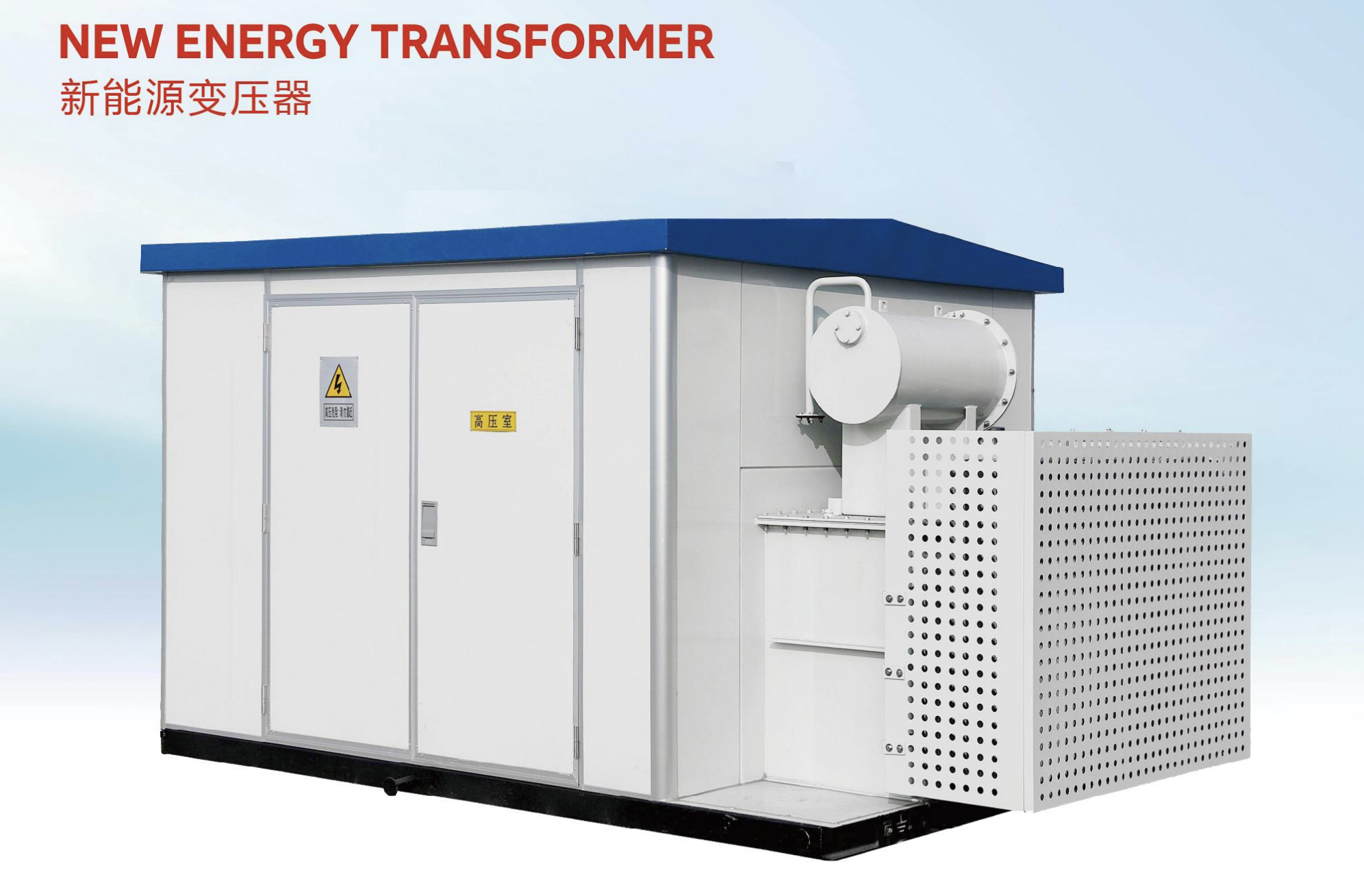
New energy transformer units are configured for PV, wind and energy-storage applications, with oil-immersed, dry-type or prefabricated-cabin construction.
| Consideration | Prefabricated cabin substation (YBM / ZGS11 / ZGS13) | Conventional civil-built substation |
|---|---|---|
| Where the assembly work happens | Equipment installed, tested and commissioned at the factory, then transported in modules for site connection | Equipment delivered separately and assembled, wired and tested on site |
| Scope integrated in the module | HV switchgear + transformer + LV switchgear + compensation + automation system + AC/DC supply + environmental control | Each system procured and coordinated separately on site |
| Site works | Transport as a complete unit, crane lifting and on-site connection | Foundations, building, cable trenching and installation labour on site |
| Environmental envelope | IP54 / IP55; –40 °C to +50 °C; high altitude, high humidity, dust and salt-spray environments | Depends on the building design and on the individual equipment ratings |
| Expansion path | Modular and expandable; capacity upgrades require additional cabins | Expansion normally requires new civil construction |
| Operation | Integrated automation with temperature, humidity, smoke, water-ingress and access monitoring; remote monitoring and unattended operation | Depends on the automation package specified and on site staffing |
The scenario logic is therefore straightforward. A prefabricated compact substation suits a remote generation site where civil capability is thin, where construction time is the binding constraint, and where the module can be lifted into position. It is also the natural choice for overseas EPC projects in areas with limited transport access, and for temporary or relocatable municipal and mine power supply. A conventional civil-built substation remains the better answer where the site already has the civil capability, where the station is part of a larger permanent building, or where the required capacity exceeds the containerized envelope and would force a full customization of cabin dimensions.
Certification is a scenario variable, not paperwork
Destination-market certification changes the technical specification, so it belongs in the scenario assessment rather than at the end of the purchase. The pattern that matters is that a certificate must be current, in the correct legal entity name, and must cover the exact product family being purchased.
- IEC markets, including the European Union. 10 kV and 35 kV power transformers and box-type substations are supplied to IEC conformity, and dry-type units to IEC 60076-11.
- North America. UL certification issued by Underwriters Laboratories and CSA certification issued by the Canadian Standards Association apply to the relevant product families, with ANSI/IEEE insulation levels and DOE 2016 / CSA 2023 efficiency requirements for pad-mounted products.
- China. GB 20052-2024, the minimum allowable values of energy efficiency and energy efficiency grades for power transformers, took effect on 1 February 2025 and sets the efficiency grades referenced on oil-immersed distribution transformers.
- United States, forward-looking. The DOE 2024 rule for distribution transformers moves the market towards amorphous electrical steel from 2029, under 10 CFR Part 431.
- Independent verification. Type-test evidence forms the strongest third-party proof — the portfolio includes a KEMA Labs Type I Inspection Report for a 250 MVA / 345 kV three-phase power transformer.
Management-system certification is a separate layer. ISO 9001:2015, ISO 14001:2015 and ISO 45001:2018 certifications are held by the audited manufacturing partners, alongside a provincial metrology qualification, CQC product certification for box-type substations and switchgear product lines, and routine, type and special test reports covering dry-type, oil-immersed and box-type substation families.
How these scenarios have been delivered
Scenario fit is best evidenced by projects where the site conditions matched the selection.
| Site type | Project reference | What it demonstrates |
|---|---|---|
| Grid-scale energy storage | 40,000 kVA energy storage project for a Bulgarian transmission company, 3 units, energy-saving transformer model S(B)H15(21–25)-M, design through commissioning, operating since 2023 | Energy-saving transformer applied to a storage grid-connection scenario |
| Solar PV plant | European PV market, multiple 40 MVA transformers (115 / 158 kV class) and a 25 MVA transformer, with multi-winding YNyn0d11 design, delivered and commissioned | Large-capacity multi-winding step-up for PV grid connection |
| Pad-mounted distribution | 15 MVA pad-mounted transformer project for a US transmission company | North American product compliance for distribution assets |
| Heavy industry step-up | 132 kV power transformer for a steel plant substation in Seville, Spain | High-voltage industrial load duty |
| Cold-climate grid station | 110 kV substation, 6 units of transformer equipment, Mongolia | Cold climate operation and full substation supply |
| Island grid reliability | 115 kV substation transformer equipment for a Puerto Rico distribution company, including 40 MVA class units | Island grid stability and logistics to an island port |
Other references in the same portfolio include 4 × 110 kV power transformers for a power energy company in Azerbaijan, a 115 kV substation in Tajikistan, a 69 kV transformer project and a commercial development in the Philippines, a 75,000 kVA / 230 kV substation transformer in Ecuador, and a 345 kV fully insulated power transformer for a US–Georgia transmission company.
Where scenario fit has limits
A useful reference states its boundaries. Four limits matter when applying the guidance above.
The supply model. Apex Power Systems is a trading and supply-partner company and is not itself the manufacturer. All manufacturing, certification and test references belong to its audited manufacturing partners. Buyers whose contract structure requires a single-factory warranty should confirm that structure explicitly at enquiry stage, because the accountabilities differ from buying directly from a plant.
Prefabricated cabins are not free of site work. Factory prefabrication removes assembly and testing from the site, but it does not remove the need for crane access, a prepared base, cable connection and grid-side protection coordination. A site without lifting access for a complete module will not benefit from the format.
Dry-type units still need protection. Cast resin dry-type transformers are supplied with IP00, IP20 or IP23 protection depending on configuration. That is adequate indoors or in a controlled enclosure; it is not the same as the IP54 / IP55 enclosure of a cabin, so a dry-type unit placed outdoors in a dusty or coastal environment needs an enclosure or a building around it.
Tap changing is stage-dependent. The New Energy Transformer uses off-circuit tap changing at ±2×2.5% or ±5%. Where a site requires voltage to be regulated while the transformer remains energised, that requirement cannot be met by an off-circuit tap changer and moves the specification into the power transformer class with on-load tap changing.
What the market direction means for specification
Three signals point the same way. First, the distribution transformer segment is projected to grow at 9.1% annually to 2033, which means more units bidding for the same engineering attention and a rising premium on selection criteria that can be applied consistently. Second, the box-type substation market for photovoltaics alone is estimated at USD 4.54 billion in 2026, which reflects how often the packaged station is now the default delivery format for a solar site rather than an alternative to it. Third, energy-efficiency regulation is becoming the binding constraint — GB 20052-2024 in China and the DOE 2024 rule in the United States both push specification towards lower-loss core materials, which is where amorphous alloy transformers already sit, with no-load losses 60–80% below conventional silicon-steel cores.
The trade data reinforces the same conclusion from the demand side: transformer trade above 500 kVA grew 12.7% year on year to USD 2.5 billion in 2024, so cross-border specification decisions are being made more often, and the destination-market certificate is now as much a part of the technical envelope as the impedance value.
Future outlook
The scenario-fit logic described here is likely to tighten rather than loosen. Several directions are already visible in the current product data. Wide-range low-voltage windings at 0.4–1.14 kV exist precisely because inverter fleets are mixed on real projects, and that tolerance is becoming a specification norm rather than a feature. Modular cabin design allows capacity upgrades by adding cabins rather than rebuilding, which suits plants that are built in phases. Monitoring is moving into the transformer itself — temperature and oil-level monitoring, pressure relief and Buchholz protection on oil-immersed units, and online oil dissolved-gas monitoring with remote communication interfaces on new energy units — which changes the maintenance model at remote sites where sending an engineer is expensive. And where construction time is the constraint, factory prefabrication of the complete station can shorten site construction time substantially compared with assembling equipment on site.
For a buyer, the practical implication is to fix the scenario before fixing the capacity: level of the plant, insulation medium, cooling class and certificate regime. Only then does comparing quotations between suppliers produce a meaningful result, because two transformers with the same kVA rating, different cooling stages and different certified product families are not the same procurement.
Frequently asked questions
Which custom transformer types fit a solar PV or wind collector substation?
For the inverter step-up and collector level, the relevant family is the New Energy Transformer, rated 500–12,500 kVA at 10 kV class and 1,000–12,500 kVA at 35 kV class, with HV 10 / 10.5 / 11 / 35 / 38.5 kV and a wide low-voltage range of 0.4–1.14 kV that is designed to suit inverters from different brands. Vector groups Dyn11 or Yd11 and impedance voltage of 6.0–14.0% cover different system short-circuit capacities. Where the same station also supplies auxiliary or distribution loads, the Energy-Saving Transformer at 30–2,500 kVA oil-immersed or 500–2,500 kVA dry-type, or the Oil-Immersed Distribution Transformer at 30–3,150 kVA (10 kV class) and 3,150–31,500 kVA (35 kV class), is used instead. Cast resin dry-type units are also specified for step-up applications at solar, wind and energy-storage plants.
When does a remote generation site suit a prefabricated cabin substation rather than a civil-built substation?
A prefabricated cabin substation is a factory-assembled unit at 10 or 35 kV with transformer capacity from 500 to 50,000 kVA, integrating HV switchgear, transformer, LV switchgear, compensation equipment, an automation system, AC/DC power supply and environmental control in a container-dimension enclosure rated IP54 or IP55 for –40 °C to +50 °C. It suits remote renewable sites where site labour and civil works are constrained, because assembly, testing and commissioning happen at the factory and the module is transported as a complete unit and lifted into place with only on-site connection remaining. A conventional civil-built substation remains appropriate where the site already has civil capability, where the station forms part of a larger permanent building, or where no crane access exists for a complete module.
How is the dry-type versus oil-immersed choice made at collector and step-up level?
The choice follows four checks. First, location: epoxy resin cast dry-type transformers contain no insulating oil, are flame-retardant and can be installed close to the load, which is why they are used in fire-sensitive and occupied locations, while oil-immersed units are normally placed outdoors or in a separate compartment. Second, capacity and voltage: dry-type SCB12–SCB18 covers 30–2,500 kVA at 10 kV class and 800–25,000 kVA at 35 kV class, while oil-immersed S13 / S14 / S15 covers 30–3,150 kVA at 10 kV class and 3,150–31,500 kVA at 35 kV class. Third, load profile: dry-type units reach up to 150% of rated load with forced-air cooling, whereas oil-immersed distribution units rely on natural oil circulation. Fourth, environment: dry-type units operate normally at 100% humidity and can be energised after shutdown without pre-drying, while oil-immersed units can be specified with No. 45 low-temperature oil or FR3 natural ester oil where cold or environmental constraints apply.
What do the cooling class codes ONAN and ONAF mean for a renewable energy transformer?
The cooling class is the four-letter code on the nameplate describing how the unit is cooled and therefore how much load it may carry. O stands for oil, A for air, N for natural circulation and F for forced circulation. ONAN therefore means oil-immersed with natural oil circulation and natural air circulation, while ONAF adds fans that force air across the radiators and raise the permissible loading. Because one transformer can carry two ratings, one per cooling stage, the guaranteed capacity is not a single figure and the cooling stage must be stated consistently on the enquiry, the nameplate and the acceptance test. The cooling class must also be checked against the ambient temperature and altitude of the site. The New Energy Transformer is offered with ONAN or ONAF cooling, and the 250 MVA / 345 kV power transformer reference uses ONAN, ONAF1 and ODAF2 stages rated at 185 MVA, 225 MVA and 250 MVA respectively.
Which certifications should a renewable project transformer hold for its destination market?
The requirement is a standards-based design plus a market-specific certificate that names the exact product family being purchased. For the European Union and most IEC markets, 10 kV and 35 kV power transformers and box-type substations are supplied to IEC conformity, and dry-type units to IEC 60076-11. For North America, UL and CSA certification apply, with ANSI/IEEE insulation levels and DOE 2016 / CSA 2023 efficiency for pad-mounted products. China's minimum energy-efficiency requirements are set by GB 20052-2024, effective 1 February 2025, and the U.S. DOE 2024 rule for distribution transformers moves towards amorphous electrical steel from 2029 under 10 CFR Part 431. Independent verification is available in the form of a KEMA Labs Type I Inspection Report for a 250 MVA / 345 kV transformer tested to IEC 60076-1/-2/-3, IEC 60076-10, IEC 60076-11 and IEEE Std C57.12.00 / C57.12.90.
Product ranges, capacities, cooling options and certification coverage for these transformer families are set out in the Apex Power Systems catalog, which can be downloaded for specification reference.