Designing Pad Mounted Transformers for Multi-Array PV and Uneven Loads
A pad mounted transformer is a distribution transformer installed inside a locked, tamper-resistant enclosure at grade level, connected to an underground primary feeder and supplying low-voltage circuits from the same pad. In North America, three-phase pad-mounted distribution transformers are commonly specified under IEEE C57.12.34, which covers ratings up to 10 MVA and 34.5 kV. The practical difficulty is not the definition. It is that most pad-mounted units are ordered as catalog items - one primary voltage, one secondary voltage, one kVA rating, one fixed tap arrangement - while a growing share of photovoltaic and commercial projects no longer fits that shape.
Projects that bring several PV arrays or inverter blocks to one interconnection point, and sites whose load is uneven across phases, inverters or hours of the day, sit outside those assumptions. The usual response is not a larger transformer. It is a different winding arrangement, a different set of secondary outputs, a different tap range and a different protection scheme, which is the territory of ODM engineering. The sections below set out the failure modes, the configuration options available in Winley Electric's pad-mounted range, and what a delivered 31-unit North American order shows about multi-specification ODM production.
Why a standard pad mounted transformer assumes a simpler project
Three assumptions sit behind the standard pad-mounted catalog configuration. Each is a procurement convenience rather than a technical requirement.
One interconnection point. A catalog unit is built with a single primary feed, loop or radial, and a single secondary. The intended project has one point where the transformer connects to the distribution system and one point where power leaves toward the loads. When a site has several inverter groups, each producing at its own voltage and current, a single secondary forces every group onto the same winding.
Broadly balanced loading. Standard three-phase pad-mounted ratings are published as a single kVA figure, which implicitly assumes the three phases carry roughly similar current and that the load profile is reasonably predictable. Uneven loading is normally handled by selecting the next size up rather than by re-configuring the transformer.
Largely one-directional power flow inside a defined voltage window. Distribution transformers are traditionally sized and tapped for power flowing from primary to secondary. A PV project spends part of every day pushing power in the opposite direction, which lifts voltage along the feeder.
Multi-array PV and mixed-use commercial sites violate all three assumptions at the same time, and the mismatch tends to appear as lost thermal margin, voltage excursion and site complexity rather than as one obvious failure.
What multi-point PV interconnection and uneven loading do to a transformer
Thermal margin disappears before the nameplate does
A transformer loaded unevenly across phases or windings generally reaches its hottest-spot limit before it reaches its rated kVA, because the additional losses in the more heavily loaded phase produce additional heat in a tank whose cooling surface was sized for balanced operation. On a site where three arrays have different string counts, different orientations and different inverter ratings, that imbalance is not a transient. It is the normal operating condition for most of the day.
Several inverters sharing one secondary
When multiple inverter outputs are paralleled onto a single secondary, the combined current profile becomes harder to predict, because each inverter follows its own irradiance, its own maximum power point behaviour and its own start-stop cycle. Inverter harmonics also accumulate on the shared winding, and harmonic currents increase winding and stray losses. Solar applications in North America are specified with those conditions in mind: step-up and reverse power flow capability, tolerance of fluctuating output and daily load cycles, inverter harmonic tolerance, lightning and surge protection, resistance to high temperatures and harsh outdoor conditions, and low losses are standard requirements, together with supporting equipment such as PV modules, inverters, combiner boxes, MV switchgear, RMU, reclosers, protection devices, SCADA and medium-voltage cables.
Voltage regulation when the site is exporting
Midday export raises voltage at the point of interconnection, and the transformer is the first place where that can be corrected. A fixed tap with little adjustment range leaves the designer with unattractive options such as moving to a higher primary voltage class or accepting curtailment. Multi-tap and multi-step tap arrangements exist for this reason. Configurations in the range include a 3750 kVA pad-mounted unit at 12.87 kV to 480Y/277 V with a seven-step tap changer, and a 150 kVA, seven-voltage unit covering 11.5-14.4 kV to 208Y/120 V, both used to standardize feeders that see different source voltages along their length.
Grounding and fault current in a collector system
Where several arrays or storage blocks are collected onto one medium-voltage bus, grounding design has to control fault current rather than simply provide a neutral. Zig-zag grounding pad-mounted transformers, such as a 5000 kVA, 27.6 kV unit, are used in solar collector systems for that purpose.
Site footprint, cabling and maintenance
The alternative to a multi-point transformer is one transformer per group. That multiplies pads, trenches, cable terminations, grounding electrodes and inspection points, and it multiplies the number of enclosures standing in publicly accessible areas, where low audible noise, tamper resistance, compact footprint and reliable grounding are already specified requirements.
What ODM customization changes
Xiamen Winley Electric Co., Ltd. (Winley Electric) is a transformer manufacturer founded in 2014, headquartered in Xiamen, China, with manufacturing facilities in Shanghai and Guangdong. The company produces transformers rated 230 kV and below, including three-phase pad-mounted transformers (model ZGS), single-phase pad-mounted transformers (model DGS), substation transformers, pole-mounted transformers, cast coil and vacuum-impregnated dry-type transformers, isolation transformers, voltage regulators and reactors. It states certification to UL and cUL as well as ISO, CE, TUV and EMC, and compliance with ANSI, IEEE, CSA, DOE 2016 and IEC 60076 standards. Export markets are focused primarily on North and South America.
Its ODM scope is the reason a multi-point problem can be solved at the transformer rather than by rearranging the whole site. Winley Electric offers OEM/ODM transformer solutions up to 10 MVA with high-voltage systems rated up to 36 kV, and customizes:
- electrical performance, including rated capacity, voltage and connection group;
- structure and appearance, including model, cabinet size and protection class;
- insulation fluid;
- protection devices, switches and gauges;
- tank coating and adaptation for extreme environments;
- extended functions including monitoring, protection and communication interfaces.
Designs are executed to customer drawings, and components from brands such as Qualitrol and Eaton Cooper can be integrated where a project calls for them. Minimum order quantity is one unit, monthly capacity is 500 units, and lead time is typically 4-8 weeks.
| Design dimension | Standard catalog pad-mounted unit | ODM-configured unit |
|---|---|---|
| Secondary arrangement | Single secondary at one fixed voltage | Multi-winding or dual-secondary outputs, each sized for its own inverter group or load zone |
| kVA rating | Fixed ladder of published ratings | Capacity set by the project loading profile, up to 10 MVA |
| Voltage regulation | Fixed taps | Multi-tap and multi-step tap arrangements for export and long feeders |
| Insulation fluid and enclosure | Standard fluid and standard finish | Project-specified fluid and corrosion-resistant enclosure, including high-fire-point and natural-ester options |
| Protection and monitoring | Limited accessory list | Customer-specified relays, switches, gauges, monitoring, protection and communication interfaces |
| Component sourcing | Manufacturer standard bill of materials | Named third-party components where specified |
| Documentation | Standard data sheet | Drawings, test reports and factory acceptance testing per customer requirements |
Configuration options for multi-point PV interconnection
In practice the engineering question is how many electrical points the transformer must present to the site, and how the kVA should be distributed among them. Winley Electric's pad-mounted range includes several configurations that answer that question differently.
Multi-winding step-up for multi-inverter PV
A multi-winding solar step-up pad-mounted transformer collects several inverter outputs on separate windings inside one enclosure. A 2.05 MVA, FR3 liquid-filled unit with three 380 V inputs stepping up to 34.5 kV at 60 Hz is built for multi-inverter PV plants. Because each inverter group has its own winding, the arrays do not have to be electrically identical to be collected at one point.
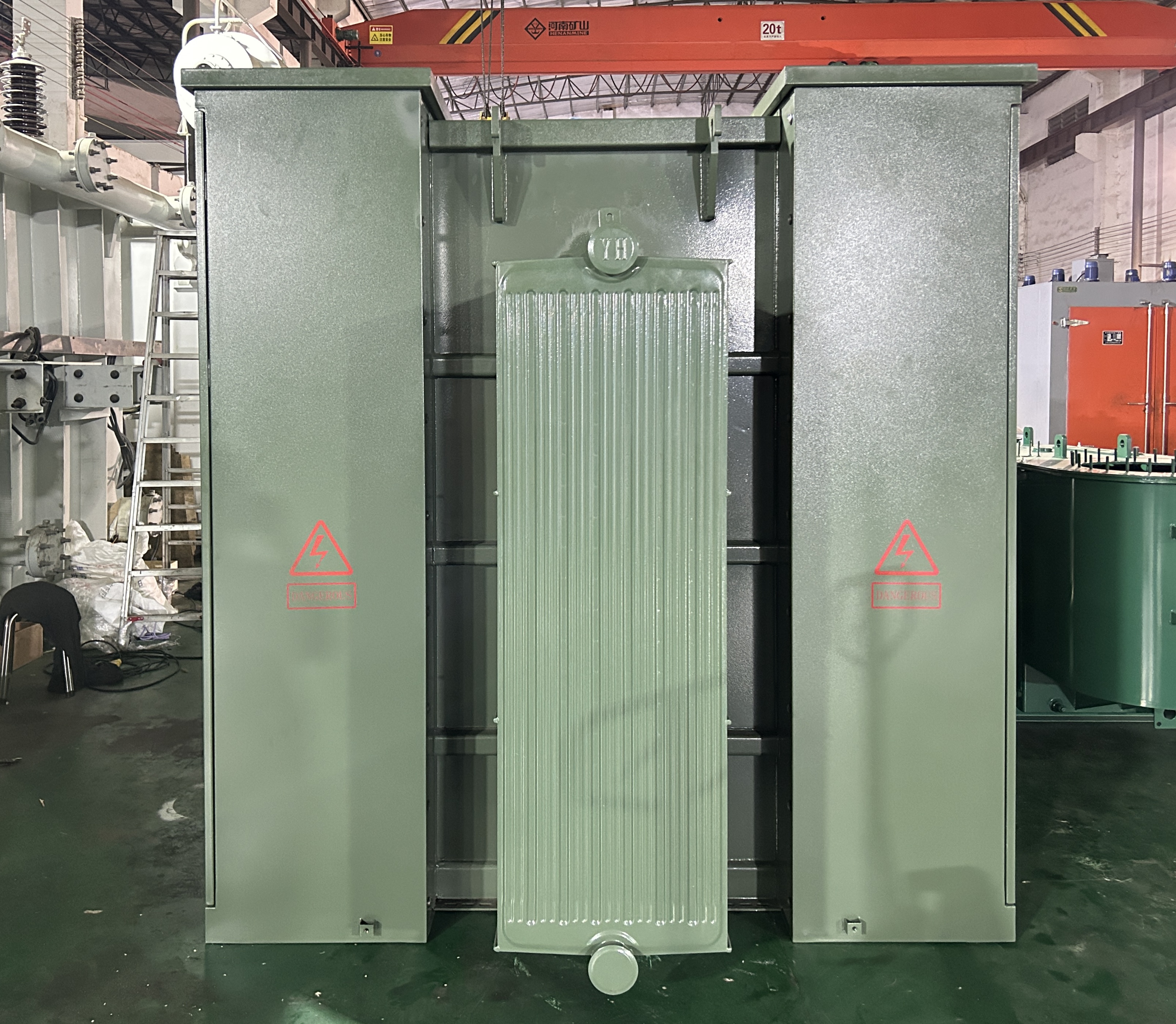
A multi-winding solar step-up pad mounted transformer: three 380 V inverter inputs collected on separate windings and stepped up to 34.5 kV inside one FR3-filled enclosure.
Dual-secondary and split-winding designs
Where the load groups are not all PV, dual-secondary designs keep them electrically distinct instead of merging them on a shared bus. Examples in the range include a 1500 kVA dual-secondary unit at 21.6/12.47 kV feeding 995 V and 480Y/277 V for separate equipment and building-service loads, and an 8 MVA, 34.5 kV unit with dual 480 V split windings for multi-bus distribution. On the generation side, double-split step-up transformers such as a 6500 kVA unit stepping 480 V up to 13.8 kV are used to aggregate several inverter blocks onto one primary connection.
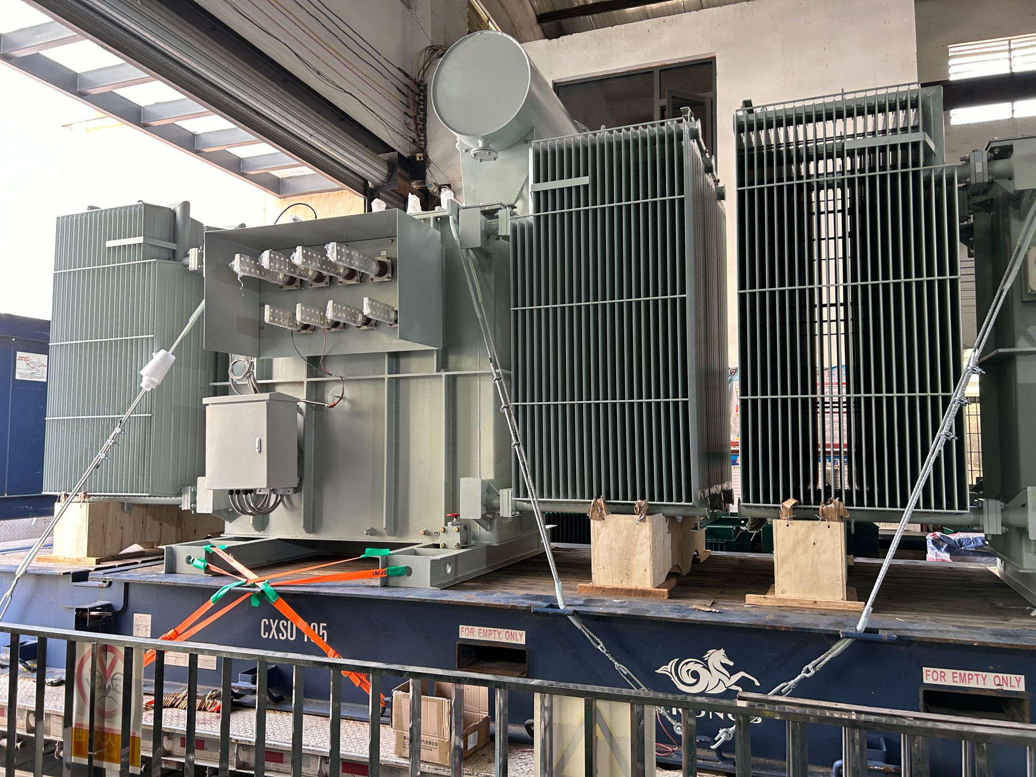
A double-split step-up transformer used to aggregate multiple inverter blocks onto a single medium-voltage primary connection.
Tap arrangements and voltage range
A wider tap range turns one transformer into a feeder-standardization device. Rather than stocking several primary voltage classes, a specifier can select a unit whose tap range covers the voltages actually present on the feeder, and adjust in the field as the network changes.
Grounding, fluid and enclosure
Collector systems and public-access sites often need more than a standard tank. Options in the range include zig-zag grounding units for solar and storage collectors, natural-ester and FR3 dielectric fluids for high-fire-point locations, and 304 stainless steel NEMA 4X tanks for coastal and high-corrosion environments.
Protection and communication interfaces
Because multi-point sites have more to coordinate, protection and monitoring become part of the transformer specification rather than an afterthought. Customer-specified relays, switches, gauges and communication interfaces are part of the customizable scope, and third-party components can be integrated where a utility or engineering firm requires a specific brand.
A delivered North American example: 31 units across two ratings
A recent order shows what multi-specification ODM production looks like in practice. Winley Electric produced 31 three-phase pad-mounted transformers for a United States-based electricity utility customer in a single batch, covering two core ratings: 2550 kVA and 3750 kVA, with high-voltage ratings of 34.5 kV and 12.87 kV. The batch was completed within the agreed timeframe. The three-phase pad-mounted series carries UL and cUL certification, and the units were built to ANSI/IEEE standards with core efficiency metrics meeting and frequently exceeding DOE 2016 requirements. The application scope recorded for the order covers large commercial and retail complexes, edge and mid-scale data centers, industrial manufacturing and logistics, renewable energy and EV infrastructure, and multi-family residential and microgrids.
Two characteristics of that batch matter more than the unit count. First, two different kVA ratings and two different primary voltages were engineered and produced as one order, which is the operational behaviour ODM procurement depends on when a site portfolio is not uniform. Second, configuration was driven by the customer application scenario and North American standards rather than by a catalog list.
What the example does not establish: a 31-unit multi-rating batch is evidence of engineering and production capability under North American standards, not proof that every multi-array PV project needs the same winding arrangement. Winding configuration, kVA split, tap range and protection scheme are determined by the site loading profile, the grounding study and the utility interconnection requirements, and are confirmed on approved drawings before production.
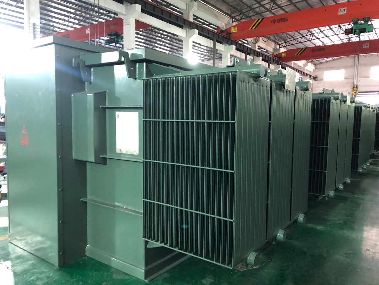
A 3750 kVA three-phase pad mounted transformer from the 31-unit North American order, which also included 2550 kVA units at 34.5 kV and 12.87 kV.
Where these configurations are used
The same engineering choices recur across several project types, and it is usually the load shape rather than the industry label that decides the configuration.
- Solar and PV. Utility-scale solar farms, commercial and industrial PV, distributed solar and solar-plus-storage projects step up inverter output of 208 V, 380 V, 480 V, 600 V or 800 V to 13.8 kV, 24.94 kV or 34.5 kV for collection and grid interconnection, and also provide step-down power for plant auxiliary loads.
- Commercial and institutional campuses. Commercial real estate, healthcare facilities, higher education, K-12 education, hospitality, retail and public institutions convert 34.5 kV, 24.94 kV, 13.8 kV, 12.47 kV, 11 kV or 4.16 kV to 480Y/277 V, 208Y/120 V, 600Y/347 V, 433 V or 415 V for HVAC, lighting, elevators, kitchens, laboratories and central utility plants, under variable daytime loads and seasonal peaks.
- Industrial plants. Manufacturing sites convert utility medium voltage to 4.16 kV, 1 kV, 480 V or 415 V for production lines, motor control centers, variable frequency drives, welding equipment, compressors and pumps, often with cyclic and impact loads.
- EV charging depots. Charging hubs convert medium voltage to 480Y/277 V or 600Y/347 V for DC fast chargers and auxiliary systems, with simultaneous charger operation and rapid load changes.
- Data centers and storage. Data center distribution and battery energy storage interconnection both require tight voltage control, harmonic tolerance and, in storage applications, bidirectional power flow.
Market signals behind the shift
Published market figures should be read carefully, because definitions differ between research houses. Global Market Insights values the global pad-mounted transformer market at approximately USD 22.3 billion in 2024. Mordor Intelligence publishes USD 6.12 billion for 2025, and Strategic Market Research USD 5.2 billion for 2024. The spread reflects different scopes, in particular whether larger power transformers are partly included, so the figures should not be compared directly or treated as one agreed value.
At country level, Market Research Future estimates the United States pad-mounted transformer market at USD 3.75 billion in 2024, attributing growth to grid modernization and underground cabling. Trade data supports the direction rather than the level: global trade in liquid dielectric transformers under 650 kVA reached USD 4.08 billion in 2024, a 22.6% increase over the previous year, according to the Observatory of Economic Complexity, with South Korea, Mexico and China the leading exporters and China alone accounting for USD 511 million in 2024.
For specification work, the relevant implication is not only volume. A market expanding through undergrounding, PV additions and storage interconnection also changes the mix of configurations being ordered, toward more multi-point connections, more export-capable units and more project-specific tap and protection schemes. Major global manufacturers in the category include ABB, Eaton, Schneider Electric, Siemens Energy and General Electric, according to Mordor Intelligence, which is a useful benchmark set when comparing certification scope, testing documentation and customization depth.
Standard catalog versus ODM-configured: the real trade-off
ODM configuration is not universally better. It solves a specific mismatch, and it introduces obligations that a catalog purchase does not have.
| Consideration | Standard catalog unit | ODM-configured unit |
|---|---|---|
| Fit to a multi-point site | Requires one unit per group, or acceptance of unbalanced operation on a shared secondary | One enclosure can present several electrical points and per-group kVA |
| Front-end engineering | Minimal; select from a list | Drawings must be prepared, reviewed and approved before release to production |
| Lead time | Often available from stock or in short cycles | Typically 4-8 weeks, and dependent on drawing approval and component availability |
| Field interchangeability | High; units of the same rating can be substituted | Lower; a replacement must match the original approved drawing |
| Fleet spares planning | Simpler across many sites | Requires drawing-level records for each configuration |
| Best use case | Balanced load, one interconnection point, stable voltage | Multiple arrays or load zones, uneven loading, export-driven voltage variation |
The clearest limitation is documentation dependency. A custom pad-mounted transformer is only as good as the drawings it was built to, and any change after approval reopens the engineering cycle. Non-standard units also complicate fleet standardization: an operator with twenty identical catalog units can swap spares freely, while an operator with twenty different ODM configurations cannot. Where a site genuinely has one interconnection point and a balanced load, a catalog unit remains the more economical and more easily maintained choice.
What to fix at the drawing stage
The following items determine whether a multi-point configuration works in service, and each should be resolved before production release.
- Number and rating of each inverter group or load zone to be connected, and whether they share a winding or use separate windings.
- kVA allocation per winding, checked against the site loading profile rather than against a single aggregate figure.
- Primary and secondary voltages, connection group and the tap range needed to cover actual feeder and export conditions.
- Insulation fluid and enclosure finish, based on fire-point requirements, public access and local corrosion conditions.
- Grounding arrangement, including whether a zig-zag grounding unit is required for the collector bus.
- Protection, switching, gauging and any monitoring or communication interfaces, including any named third-party components.
- Test scope: factory routine tests, type tests where required, and whether third-party inspection or factory acceptance testing is needed.
Future outlook
As more PV, storage and EV load is connected behind the same distribution feeders, the proportion of projects with more than one generation or load point is likely to keep rising. That shifts pad-mounted transformer selection away from picking a rating from a table and toward defining a winding arrangement, a kVA split and a tap range. It also raises the value of documentation: monitoring and communication interfaces, test reports and drawing control become part of what a buyer is purchasing, not optional extras.
The countervailing pressure is standardization. Utilities and large operators gain real benefits from a small number of approved configurations, and the most durable outcome is likely to be a middle path in which a limited set of customized arrangements is developed once and then reordered across projects, rather than a new design for every site.
Frequently asked questions
What is a multi-winding pad mounted transformer used for?
A multi-winding pad-mounted transformer places more than one secondary winding, or more than one input winding, inside a single pad-mounted enclosure, so that several inverter blocks or load groups can connect without a separate transformer for each. Winley Electric's range includes a 2.05 MVA FR3 liquid-filled solar step-up pad-mounted transformer with three 380 V inputs stepping up to 34.5 kV at 60 Hz, built for multi-inverter PV plants. Similar logic applies on the load side, where a dual-secondary 21.6/12.47 kV unit feeding 995 V and 480Y/277 V keeps equipment loads and building-service loads on separate secondaries.
How does a pad mounted transformer handle uneven loading from several PV arrays?
Two design responses are available. The first is to separate the sources: give each inverter group its own winding so that unequal production is absorbed by unequal winding loading rather than by one shared secondary, and size each winding for its own expected output. The second is to size the shared rating with explicit attention to imbalance, since a transformer loaded unevenly across phases generally reaches its hottest-spot limit before its nameplate kVA. Both approaches still require the project grounding study and protection coordination to be completed, because a custom winding arrangement does not remove those requirements.
What can be customized in an ODM pad mounted transformer for a North American project?
The customizable scope covers electrical performance, including rated capacity, voltage and connection group; structure and appearance, including model, cabinet size and protection class; insulation fluid; protection devices, switches and gauges; tank coating and adaptation for extreme environments; and extended functions such as monitoring, protection and communication interfaces. Designs are produced to customer drawings, and components from brands such as Qualitrol and Eaton Cooper can be integrated for specific applications. The ODM scope extends to 10 MVA with high-voltage systems rated up to 36 kV, and the minimum order quantity is one unit.
Which standards and certifications apply to pad mounted transformers in North America?
IEEE C57.12.34 governs three-phase pad-mounted distribution transformers up to 10 MVA and 34.5 kV. IEEE C57.12.38-2025 standardizes single-phase pad-mounted transformers of 250 kVA and smaller, and IEEE C57.12.28-2023 specifies enclosure integrity for pad-mounted equipment in public-access areas. Winley Electric's three-phase pad-mounted transformers (model ZGS) are specified to IEEE/ANSI C57.12.34, CSA C227.4 and C227.5, IEC, DOE and NEMA, while the single-phase range (model DGS) references ANSI/IEEE C57.12.00, C57.12.20, C57.12.38 and C57.12.90, along with CSA, DOE and NEMA. The three-phase pad-mounted series holds UL and cUL certification, and DOE 2016 efficiency requirements apply.
What are the minimum order quantity and lead time for a custom pad mounted transformer?
Winley Electric's stated minimum order quantity is one unit, with a monthly production capacity of 500 units and a typical lead time of 4-8 weeks. Actual schedule depends on how quickly drawings are approved and on the availability of specified components, particularly where named third-party brands are required. Quality control covers factory routine tests and type tests as required by the customer. After-sales support runs for 24 months from the bill of lading, with free replacement of damaged accessories on photographic evidence, supply of consumable accessories according to unit quantity, and technical support on request.
For projects where several PV arrays or load zones terminate at one pad, the decisive question is not which transformer is largest, but which arrangement of windings, secondaries and taps matches the way the site actually produces and consumes power.
Click to view more pad‑mounted transformer projects from Winley Electric:https://www.winley-electric.com/supplier-4701740-three-phase-pad-mounted-transformer
·Website:www.winley-electric.com