
Factory Evidence: How AOYG's Tooling and QC Enable 1000+ Mating Cycles
Factory Evidence: How AOYG's Tooling and QC Enable 1000+ Mating Cycles
High-current DC power connectors have moved out of the hobby drawer and into documented supply chains. The global high power connectors market was valued at approximately USD 5.47 billion in 2025 (Fact.MR), and DC connectors accounted for 58.7% of the energy storage connector market in the same year, a share attributed to higher voltage requirements (Dataintelo). As volumes rise across energy storage, e-mobility, robotics and drone platforms, the evaluation question has shifted from "what is the rating?" to "what inside the factory makes that rating repeatable?"
A mating-cycle figure is a useful example. Most high-current connector datasheets quote one. Far fewer suppliers can describe the tooling, plating thickness, housing material, temperature-rise limit and test regime that sit behind the number. This article examines how AOYG DC Power Connector, a manufacturer of high-current DC connection systems for lithium-ion smart devices, supports a published rating of 1000 or more mating cycles across its connector families — and where the published evidence stops.
From Datasheet to Factory Floor: Why Mating-Cycle Ratings Are Being Audited
In the evaluation stage, most connector comparisons begin with the same three figures: rated voltage, continuous current and mating cycles. The comparison weakens when those figures were produced under different conditions. A cycle rating measured on an unloaded connector on a laboratory bench is not the same claim as a rating measured with the specified cable, under load, in a dusty enclosure.
Three questions separate a catalogue number from a verifiable one:
- Who owns the tooling? If the mould for the housing and the forming dies for the terminal are developed in-house, dimensional changes requested by a buyer move through a controlled process instead of a third-party queue.
- Which processes are controlled on site? Stamping, injection moulding, assembly and final test each contribute to contact stability. Outsourced steps shift corrective action outside the supplier's control.
- What evidence exists for the claim? Ratings, third-party test reports, batch records and traceability determine whether a claim can survive an audit or a field failure investigation.
For most procurement teams, the practical opportunity is not finding a supplier with a higher number on the datasheet. It is finding a supplier whose number can be traced to a process step, a material specification and a test record.
The Supplier Behind the Rating: AOYG DC Power Connector at a Glance
AOYG DC Power Connector is a China-based manufacturer and solution provider specialising in the research, development, production and customisation of high-current DC connection systems for lithium-ion smart devices. The company operates a 6,000 m² production facility with approximately 100 employees, reports annual output of 900,000 units, and supports that output with 25 engineers in R&D. Roughly 50% of production is exported, with Europe and the United States listed as the main markets and additional sales across Southeast Asia.
Two documented elements frame the quality argument. The first is IATF16949:2016 certification, the automotive quality management system standard, which the company states it has obtained and applies across the production process. That certificate is a starting point for verification rather than a conclusion: buyers can confirm the certificate number, scope and validity with the issuing certification body, and check whether the audited scope covers the connector production site. The second element is a 100% test regime at the quality-control stage, layered on incoming material inspection, precision mould development, automated production and finished-product inspection.
The connector families referenced in this article are the DXT30U series (including the 2+2 power-signal composite), the DXT60EW and DXT60W waterproof pair, the DXT90H-M and DXT90E-F Yellow pair for RC and small electric vehicles, and the DXT90H-M and DXT90S-F UAV pair.
What a 1000+ Mating Cycle Rating Actually Rests On
Published specifications across these families share a consistent set of electrical and mechanical decisions. The table below summarises the values that the manufacturer publishes for each family.
| Family and model | Rated voltage | Continuous current (stated wire) | Peak current | Contact resistance | Sealing | Mating cycles |
|---|---|---|---|---|---|---|
| Drone Connector DXT30U-M / DXT30U-F | DC 500 V | 15 A (18AWG, 20AWG compatible) | 30 A | ≤ 0.7 mΩ | IP40 | ≥ 1000 |
| Waterproof High Current Connector DXT60EW-M + DXT60W-F | DC 500 V | 60 A (8–10AWG) | 100 A | ≤ 0.8 mΩ | IP67 | ≥ 1000 |
| RC Model Electric Vehicle Connector DXT90H-M + DXT90E-F Yellow | DC 500 V | 45 A (10AWG, 8AWG compatible) | 90 A | ≤ 1.0 mΩ | IP40 | ≥ 1000 |
| UAV Connector DXT90H-M / DXT90S-F | DC 500 V | 90 A (10AWG, 8AWG compatible) | Not published | Not published | IP40 | ≥ 1000 |
| Power-Signal Combo DXT30U(2+2)-F(B) | DC 500 V | 20 A power pin (16AWG); 1 A signal pin | 35 A | ≤ 1.2 mΩ | IP40 | ≥ 1000 |
Values as published for each family. Continuous current is stated by the manufacturer for the wire gauge shown, with a temperature-rise limit of ≤ 85 °C on continuous load. Where a value is not published for a family, it is marked as such rather than inferred.
Six design decisions in these specifications support cycling endurance:
- Gold-plated H62 brass terminals. Gold plating is specified at 0.3 µm as standard, with thicker industrial gold plating available as an option. Plating thickness and adhesion are the first line of defence against the oxide build-up that pushes contact resistance upward as cycles accumulate.
- Beryllium copper spring contacts. Where the material is published — the DXT90H-M + DXT90E-F Yellow connector — the contact spring is beryllium copper with gold plating. Spring force is what keeps contact resistance stable as the mating interface wears.
- PA66 housings rated UL94 V-0. All cited families publish UL94 V-0 as the flammability class for the housing. Dimensional stability at temperature preserves the alignment of the mating interface.
- A defined temperature-rise limit. The 45 A and 90 A continuous ratings are published with a 10AWG conductor and a temperature rise of ≤ 85 °C. Heat accelerates contact degradation, so the temperature-rise limit carries as much weight as the ampacity figure itself.
- Dielectric margin. Published values include insulation resistance of ≥ 2000 MΩ and an AC 2000 V / 1 min withstand test, an explicit margin above the DC 500 V rated voltage.
- Corrosion screening. Gold-plated standard models are published as passing 48 hours of salt spray testing.
In-House Tooling: The Design-for-Manufacturing Evidence Trail
The published process description for AOYG runs from raw material incoming inspection and precision mould development through automated production and processing to finished product testing and factory inspection. Precision mould development is the step that connects the factory most directly to a 1000-cycle claim: pin position, terminal retention and housing geometry determine whether a connector mates on axis a thousand times or wears unevenly after the first hundred.
The customisation scope that sits on top of that tooling base covers size, current specification, pin position, wiring structure and logo printing. OEM and ODM development is offered from a customer's application scenario and technical parameters, and the waterproof pair is available as a pre-wired harness with custom cable lengths. In practice this means a buyer specifying a new enclosure or a different pin-out is not limited to a catalogue item.
Commercial and capacity parameters are published as follows: monthly capacity of 8,000 units, a lead time of 30–45 days, a minimum order quantity of 2 units, 100% test, and after-sales support delivered remotely.
The implication for an evaluation-stage buyer is a sequence rather than a single decision. A low minimum order quantity and a 30–45 day tooling and production window allow sample build and validation before volume commitment — the order most OEM programmes need when a housing or pin-out changes. The corresponding trade-off is capacity: 8,000 units per month is a defined ceiling, and a programme that exceeds it needs either a schedule agreed in advance or a second qualified source.
Design-for-Manufacturing Evidence: Anti-Spark, Sealing and Power-Signal Integration
Anti-spark pre-charge
The DXT90S-F female connector includes a built-in high-power precharge resistor, and other families in the range describe an anti-spark structure as optional. The function is to limit inrush current at the moment of connection. Because uncontrolled arcing attacks the same plated interface that the mating-cycle rating depends on, a pre-charge path is a durability feature as much as a safety feature — it protects the surface that determines contact resistance at cycle 10 and at cycle 1000.
IP67 sealing, on the models that carry it
The DXT60EW-M and DXT60W-F pair uses a silicone O-ring and is published at IP67, with continuous current of 60 A, peak current of 100 A and a Φ5 mm H62 brass gold-plated terminal. The stated application field covers waterborne unmanned equipment, outdoor mobile photovoltaic energy storage, marine lithium battery systems, outdoor communication backup power, outdoor 5G base station standby power, outdoor garden machinery, water operation equipment, construction machinery and outdoor electric amusement equipment.
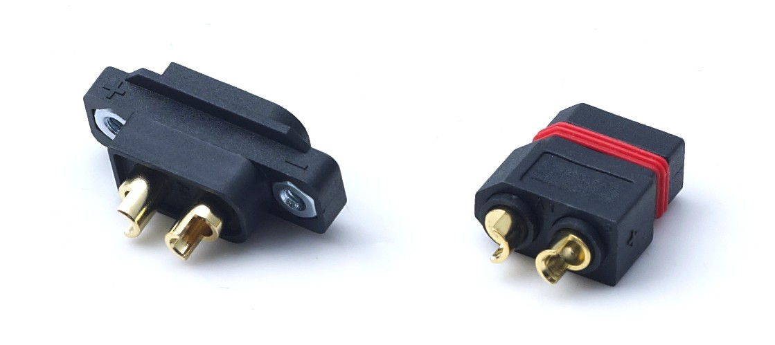
DXT60EW-M + DXT60W-F: the waterproof pair in the AOYG range, sealed with a silicone O-ring and published at IP67 with 60 A continuous and 100 A peak current.
Power and signal in one housing
The DXT30U(2+2)-F(B) composite connector carries two power pins and two signal pins — 20 A on the power pin with 16AWG wire and 1 A on the signal pin — and accepts 12–16AWG silicone wire. It mates with the DXT30U(2+2)-M and DXT30U(2+2)P counterparts. For a harness designer, combining power and signal in one interface reduces the number of separate connection points in a battery pack or robot chassis, and each removed connection point is one less interface to validate.
Vibration and keying provisions
Across the application requirements published for these connector families, the recurring mechanical demands are vibration resistance, anti-loosening retention and anti-reverse-insertion design, alongside operating temperatures from -20 °C to +120 °C.
Where These Connectors Are Used in Volume
The product line is stated as adopted by manufacturers of drones, robots, e-mobility, energy storage and power tools. The published application list is broader than those five categories and includes FPV drones, agricultural plant-protection UAVs, electric scooters, electric bicycles, portable outdoor energy storage power stations, handheld power tools, garden machinery, intelligent service robots, AGV handling robots and lithium battery pack assembly.
One documented programme illustrates the durability claim in field terms rather than laboratory terms: a 20-unit deployment with drone, robot, e-mobility, energy storage and power tool manufacturers, running in stable operation for more than two years, with products exported to Europe, America and Southeast Asia.
One application deserves separate attention because the power profile is changing fast: 5G base station backup. A typical 5G site draws 11.5 to 14 kW on average, with peaks reaching 19 kW (Telecom Site Planning Guide, February 2026). That load profile puts continuous current and thermal behaviour ahead of peak ratings in the specification, and it explains why outdoor-rated low-voltage DC connectors appear alongside battery cabinets in site designs.
Market Signals Buyers Are Responding To
Three verifiable market figures frame the evaluation context:
- The global high power connectors market was valued at approximately USD 5.47 billion in 2025 (Fact.MR, High Power Connectors Market report).
- DC connectors represented 58.7% of the energy storage connector market in 2025, a share Dataintelo attributes to higher voltage requirements.
- XT60 and XT90 remain established interface references for medium to high power RC aircraft and drone battery-to-ESC connections in 2026 (ChinaHobbyLine, RC Battery Connector Compatibility Guide, April 2026).
Taken together, these signals point in one direction for procurement: DC connection hardware is being specified as a documented component with a lifecycle cost, not as an accessory. That shift raises the value of factory evidence — tooling ownership, plating specification, test records — relative to catalogue breadth. It also means a 1000-cycle rating increasingly functions as a screening threshold rather than a differentiator: buyers use it to disqualify, then decide on the evidence behind it.
Comparison With Traditional Solutions — and Where the Limits Are
Buyers weighing a modular connector against hard-wired battery leads are comparing two different service models rather than two products. The trade-offs are structural.
| Criterion | Hard-wired or soldered battery leads | Modular high-current connector (published AOYG families) |
|---|---|---|
| Field serviceability | Requires cutting and re-soldering | Manually mated and locked; battery packs can be swapped or replaced in the field |
| Published cycling life | Not applicable to a soldered joint | ≥ 1000 mating cycles on all cited families |
| Environmental protection | Dependent on harness potting and enclosure design | IP40 as standard; IP67 on the DXT60EW-M + DXT60W-F pair |
| Inrush behaviour at connection | No pre-charge path unless added externally | Built-in high-power precharge resistor on DXT90S-F; anti-spark structure optional on other models |
| Termination method | Solder only | Cable-soldered (DXT30U(2+2)-F(B)), brass crimp sleeve, or pre-wired harness with custom length |
| Added hardware and weight | Lower component count | Adds a connector pair, housing material and weight to the assembly |
Comparison based on published specifications and published application requirements for the AOYG families referenced in this article.
An honest evaluation also has to state the limits of the evidence above.
- Sealing is model-specific, not range-wide. The published IP67 rating applies to the DXT60EW-M + DXT60W-F pair. Other families are published at IP40. Buyers specifying outdoor or wash-down equipment cannot assume the whole range carries the same ingress protection.
- Plating and corrosion performance depend on the specification chosen. 0.3 µm gold plating is the standard, and thicker industrial gold plating is an option that must be requested. The published 48-hour salt spray result applies to gold-plated standard models.
- Current ratings are conditional. A 90 A continuous figure assumes a 10AWG conductor; the 15 A figure for the DXT30U-M/DXT30U-F assumes 18AWG. Ratings also carry a ≤ 85 °C temperature-rise limit, which is a design constraint in a sealed enclosure, not a formality.
- Cycle ratings are published as a minimum without the test protocol. The ≥ 1000 figure is a design and test target; real service life depends on mating alignment, contamination, load profile and whether cable strain is managed.
- Custom tooling has a schedule. The published lead time is 30–45 days with a monthly capacity of 8,000 units, so buyers planning a new pin-out or housing should build that window into the project timeline.
- IATF16949:2016 should be verified, not assumed. Certification is a strong quality milestone, but its value in a purchase decision depends on confirming scope and validity with the issuing body and checking the audited production site.
A Verification Checklist for the Evaluation Stage
- Confirm the IATF16949:2016 certificate directly with the issuing certification body, including scope, validity and the production site covered by the audit.
- Request the third-party test reports relevant to your application, including electrical performance testing to IEC 60512 and GB/T 5095, salt spray testing to GB/T 10125 and ASTM B117, UL 94 flammability testing, RoHS 2.0 testing to IEC 62321 and REACH SVHC screening. Reports issued by laboratories accredited to CNAS, CMA and ISO17025 carry more weight than internal documents.
- Ask what the 100% test claim covers — contact resistance, withstand voltage, dimensional or functional checks — and whether results are retained per batch.
- Trace one batch from raw material to finished goods. Full lifecycle traceability is the mechanism that turns a defect report into a corrective action.
- Specify the plating and sealing grade explicitly rather than accepting the default, and confirm whether thicker gold plating or an anti-spark structure is required for your duty cycle.
- Validate with samples before committing to a custom pin-out or housing, given the 30–45 day tooling lead time.
- Confirm capacity against programme volume — 8,000 units per month per the published figure — before treating the supplier as a single source.
Future Outlook
Duty cycles in the applications these connectors serve are moving in one direction. Battery swapping in two-wheelers and light electric vehicles multiplies mating events per unit. Outdoor energy storage and 5G backup power push sealing and temperature performance. Drone and robot platforms keep reducing weight while increasing continuous current.
For suppliers, that combination rewards process control over catalogue breadth: mould ownership, plating control, defined temperature-rise limits and retained test data. For buyers, the practical change is in the request-for-quotation itself — asking for the cycle-test protocol, the plating thickness and the certificate scope before the price. AOYG's published position on this axis is a documented set of ratings, an IATF16949:2016 quality milestone, in-house tooling for custom work, and an eight-thousand-unit monthly capacity with a 30–45 day lead time. Whether that fits a given programme remains a function of the application's load profile, environment and volume — not of the rating alone.
FAQ
Does AOYG hold IATF16949 certification, and what does its quality control standard cover?
Yes. The company states that it has obtained IATF16949:2016 automotive-grade quality management system certification and that production follows automotive component quality requirements, with full-process control from raw material incoming inspection through production processing to finished product testing. The stated purpose of the system is consistent product stability, batch consistency, traceability and defect elimination. In practice, buyers should confirm the certificate number, scope and validity with the issuing certification body, and check that the audited scope covers the connector production site, rather than relying on the claim alone. The company also states a 100% test regime at the quality-control stage.
What is the flame-retardant grade of AOYG's connector housings, and what does that mean in operation?
All connector families referenced in this article publish PA66 housings rated UL94 V-0. The manufacturer states that the housing material is a high-purity flame-retardant engineering plastic rather than recycled material, offering high-temperature and melt resistance, self-extinguishing behaviour under abnormal overheating or sparking, and stable insulation performance. A UL94 V-0 flammability test report to the UL 94 standard is issued by a third-party laboratory accredited to CNAS, CMA and ISO17025. For buyers, the relevant point is that a V-0 housing protects the mechanical alignment of the contact interface during continuous high-current operation, since a housing that softens would allow terminal displacement and a rise in contact resistance.
Do AOYG's continuous current ratings assume specific conditions?
Yes. Continuous current is published together with the conductor gauge and a temperature-rise limit. The DXT90H-M / DXT90S-F UAV connector is rated for 90 A continuous on 10AWG wire with temperature rise ≤ 85 °C, compatible with 8AWG. The DXT90H-M + DXT90E-F Yellow connector is rated for 45 A continuous on 10AWG with a 90 A short-term peak. The DXT60EW-M + DXT60W-F waterproof pair is rated for 60 A continuous and 100 A peak with 8–10AWG wire. The DXT30U-M / DXT30U-F drone connector is rated 15 A continuous and 30 A peak with 18AWG wire, compatible with 20AWG. The DXT30U(2+2)-F(B) carries 20 A on the power pin with 16AWG wire and 1 A on the signal pin, accepting 12–16AWG silicone wire.
What determines whether a high-current connector survives 1000 mating cycles?
Four documented factors dominate. First, terminal plating: the families use H62 brass with gold plating specified at 0.3 µm as standard, with thicker industrial gold plating optional, plus beryllium copper gold-plated spring contacts where published. Second, spring force retention, which keeps contact resistance stable as the interface wears — published contact resistance ranges from ≤ 0.7 mΩ to ≤ 1.2 mΩ depending on the family. Third, housing dimensional stability, supported by PA66 UL94 V-0 material across an operating range of -20 °C to +120 °C. Fourth, thermal load, since continuous current is tied to a ≤ 85 °C temperature-rise limit and heat accelerates contact degradation. The manufacturer publishes the ≥ 1000 cycle rating as a minimum but does not publish the cycle-test protocol, so buyers should request mating force, load and environmental conditions if the rating must be compared directly against another supplier's figure.
Can AOYG provide technical support for product matching and debugging?
The company states that it provides free model selection guidance, product adaptation analysis and assembly solution suggestions, along with support for sample machine debugging and optimisation. Customisation covers size, current specification, pin position, wiring structure and logo printing, with OEM and ODM development based on the customer's application scenario and technical parameters. After-sales support is provided remotely. Published commercial parameters for custom work are a monthly capacity of 8,000 units, a lead time of 30–45 days and a minimum order quantity of 2 units.