
Fuse Switch Disconnector and Fuse Base Shortlist for LV Panels
A buyer-oriented shortlist of fuse switch disconnectors, fuse rails and fuse bases for low-voltage distribution panels, organized by use case and limited to documented ratings, construction and test evidence.
A low-voltage distribution panel clears faults in its feeder layer, and that layer is normally built from two component families: fuse switch disconnectors, which combine manual isolation with fuse-based protection, and fuse bases, which hold the fuse link on a busbar run, a rail or a DIN rail. Both are traded under familiar names — fuse switch, vertical fuse switch, fuse rail, fuse holder — yet their documented ratings differ enough that a shortlist built on a single headline current tends to fail later, at the panel drawing stage.
This shortlist is written for buyers in the evaluation and execution stages, where the question is no longer what a fuse does but which documented option fits a given busbar pitch, fault level, current rating and enclosure environment. It covers the Stripe Fuse rail and the Stripe Fuse Switch Disconnector models BTR1 through BTR6, the Stripe Fuse rail with hook-type busbar installation, the BH-400 DIN rail type fuse base at 690 V and 400 A, and the NT/NH fuse base models NT00, NT1, NT2 and NT3 used together with NT NH fuse links.
These products are made by BARFUSE Electric Co., Ltd. (Yueqing Barfuse Electric Co., Ltd.), a manufacturer based in Yueqing, Zhejiang Province, China, whose range covers low-voltage fuse switch disconnectors, busbar systems and high and low voltage distribution wiring management products, including MCB and MCCB pan assemblies and metal distribution boxes. The company was founded in 2014 and reports a 10,000 ㎡ factory, 45 employees, a seven-engineer R&D team and an annual output of 250,000 pieces, with about 90% of sales exported to the Middle East, Russia, Latin America, Central Asia, the EU, Africa and Oceania.
Why the protection layer is being re-specified now
Three changes are visible in the public record, and each one changes what a buyer should be able to verify.
First, the fuse standard has moved. IEC 60269-1:2024 sets out general requirements for low-voltage fuses covering AC up to 1000 V and DC up to 1500 V, and it is listed as active with an effective date of 9 August 2024. A specification that only documents AC behaviour leaves the DC column of a modern panel unanswered.
Second, panel geometry has settled around defined busbar pitches. Vertical fuse switch disconnectors are optimized for 185 mm and 100 mm busbar spacing systems in low-voltage networks, which makes mounting pitch a first-order selection criterion rather than a drawing detail resolved at the end of the project.
Third, the market itself is expanding. The global electric fuse market is projected to reach USD 5.84 billion in 2025 and to grow at a CAGR of 7.05% towards 2034, according to Fortune Business Insights. Inside that total, the 800 V DC protection segment for data centers is estimated at USD 265 million in 2026 with a 29.9% CAGR — a smaller, faster-moving pocket where the vocabulary of DC fuse, PV fuse holder and photovoltaic fuse now sits alongside conventional fuse switch terminology.
For a panel builder, the practical consequence is straightforward: AC rating tables, breaking capacity and busbar spacing should stay as separate lines in the evaluation instead of being collapsed into one general decision about fuse protection.
The criteria used to build this shortlist
Every option below is described with the same seven documented data points, so that the comparison stays on verifiable ground.
- Rated operation current, documented as Ie on the switch disconnectors and as Ith on the rail models.
- Rated operation voltage Ue, documented at 415 V, 500 V and 690 V across the BTR family and up to 1140 V across the NT/NH family.
- Insulation and impulse withstand values, documented as Ui 1000 V and Uimp 10 kV on the BTR1 to BTR5 models.
- Busbar distance, documented as 100 mm and 185 mm unit options on BTR6.
- Breaking capacity, documented up to 120 kA on the NT/NH fuse links.
- Construction materials, documented as COPPER + DMC with ABS and PC on selected models, ceramic and tin-plated copper on NT/NH bases, and ceramic with silver-plated copper on NT NH fuse links.
- Standard alignment and third-party evidence, including IEC/EN 60269 on BTR6, IEC 269 on the NT/NH family, type test report V160016, VDE certificate NO.40047494 and ISO 9001 certificate 62724Q1160R0S.
Option family A: Stripe Fuse rail and Stripe Fuse Switch Disconnectors, BTR1 to BTR6
The BTR family splits into two mechanical roles. BTR1 and BTR2 are Stripe Fuse rails — the carrier that positions a fuse on a busbar run and gives the panel its hook-type busbar installation pattern. BTR3, BTR4 and BTR6 are Stripe Fuse Switch Disconnectors, which add the manual switching function to the same busbar-mounted concept. BTR5 is documented as a Stripe Fuse fuse rail in the same electrical class as the switch disconnectors.
The distinction matters during procurement, because a rail and a switch disconnector are not interchangeable line items: the rail fixes the mounting pitch and the current path, while the disconnector determines whether the feeder can be isolated locally at the panel.
Documented parameters of the BTR range
| Model | Documented type | Rated current | Ue | Other documented data |
|---|---|---|---|---|
| BTR1 | Stripe Fuse rail | 250 A / 400 A / 630 A | 415 V / 500 V / 690 V | 50/60 Hz; Ui 1000 V; Uimp 10 kV; COPPER + DMC |
| BTR2 | Stripe Fuse rail | 250 A / 400 A / 630 A (Ith) | 415 V / 500 V / 690 V | 50/60 Hz; Ui 1000 V; Uimp 10 kV; IP30; COPPER + DMC + ABS + PC |
| BTR3 | Stripe Fuse Switch Disconnector (BTR3-250 / 400 / 630) | 250 A / 400 A / 630 A | 415 V / 500 V / 690 V | 50/60 Hz; Ui 1000 V; Uimp 10 kV; IP30; COPPER + DMC |
| BTR4 | Stripe Fuse Switch Disconnector (BTR4-250 / 400 / 630) | 250 A / 400 A / 630 A | 415 V / 500 V / 690 V | 50/60 Hz; Ui 1000 V; Uimp 10 kV; IP30; COPPER + DMC + ABS + PC |
| BTR5 | Stripe Fuse fuse rail (BTR5-250 / 400 / 630) | 250 A / 400 A / 630 A | 415 V / 500 V / 690 V | 50/60 Hz; Ui 1000 V; Uimp 10 kV; IP30; COPPER + DMC + ABS |
| BTR6 | Stripe Fuse Switch Disconnector | Ie 160 A | AC 690 V | Busbar distance 100 mm / 185 mm; IEC / EN 60269; COPPER + DMC + ABS + PC |
Two patterns emerge from the table. The 250 A, 400 A and 630 A class behaves consistently across BTR1 to BTR5, including the 1000 V insulation value and the 10 kV impulse withstand value, so moving a feeder from a rail to a switch disconnector inside that class generally does not change the electrical environment around it. BTR6 sits in a different place: it is a 160 A device documented against IEC/EN 60269 and specified by busbar distance rather than by a 630 A class current.
That is why BTR6 is the natural candidate for panels laid out on 100 mm busbar spacing, where a 160 A feeder needs a compact fuse switch disconnector rather than a full-width device. The same model also documents a 185 mm variant, which lets one product family be carried across two panel standards without a second supplier qualification.
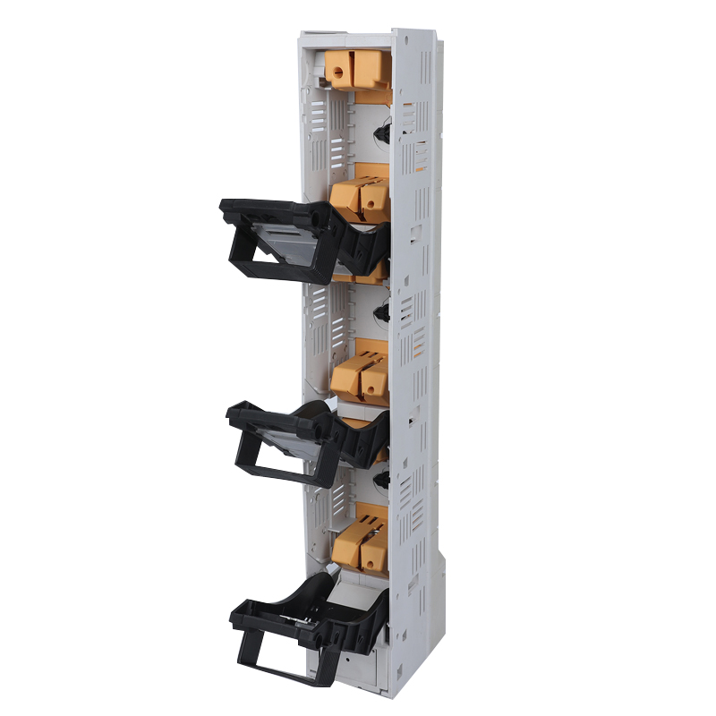
Option family B: NT/NH fuse bases NT00, NT1, NT2 and NT3 with NT NH fuse links
Where fault level or voltage pushes beyond the busbar-mounted range, the NT/NH family takes over. The NT/NH fuse base is documented for circuits of AC 50 Hz with a rated voltage up to 1140 V and a rated current up to 630 A, while the fuse links carry a breaking capacity up to 120 kA and conform to the standards of IEC 269. Bases are constructed from ceramic and tin-plated copper. The corresponding NT NH fuse links share the AC 50 Hz and 1140 V envelope, extend the rated current to 1250 A, hold the same 120 kA breaking capacity and use ceramic with silver-plated copper.
The base and the link are documented as a pair, and that is the detail buyers should hold on to: NT00, NT1, NT2 and NT3 describe sizes, while the practical assembly performance is defined by the link's breaking capacity rather than by the base alone. The documented applicable industry for this family is industrial application and commercial building electric management — the two environments where prospective fault current is higher and service intervals are longer.
Operationally, an NT/NH assembly is not a switching device. Removing or replacing a link normally requires a fuse puller or a fuse handle sized to the link, and isolation is provided by an upstream or adjacent disconnector. Panels specifying this family should therefore plan both the link inventory and the physical access needed for safe replacement.
Option family C: the BH-400 DIN rail type fuse base
Not every panel is built on busbar runs. The BH-400 DIN rail type fuse base is documented at 690 V and 400 A, which places it in the modular, DIN rail-mounted segment of low-voltage distribution panels. For the buyer, the constraint it changes is geometric: instead of a 100 mm or 185 mm busbar pitch, the layout is driven by DIN rail space, panel depth and the upstream disconnecting means. The BH-400 is therefore shortlisted for compact modular enclosures and retrofit work rather than as a substitute for a 630 A class busbar device.
Shortlist by use case
| Use case | Documented option | Documented basis |
|---|---|---|
| Compact modular panels, 100 mm busbar spacing | BTR6 Stripe Fuse Switch Disconnector | Ie 160 A; Ue AC 690 V; busbar distance 100 mm / 185 mm; IEC / EN 60269 |
| Busbar-run feeders in the 250 A to 630 A class | Stripe Fuse rail BTR1 / BTR2 / BTR5 and Stripe Fuse Switch Disconnector BTR3 / BTR4 | Ue 415 V / 500 V / 690 V; Ith 250 A / 400 A / 630 A; Ui 1000 V; Uimp 10 kV; IP30 |
| High breaking capacity needs | NT/NH fuse base NT00 / NT1 / NT2 / NT3 with NT NH fuse link | Up to 1140 V; base up to 630 A; link up to 1250 A; breaking capacity up to 120 kA; IEC 269 |
| DIN rail mounting inside modular enclosures | BH-400 DIN rail type fuse base | 690 V; 400 A |
| Industrial and commercial building electric management | NT/NH fuse base and NT NH fuse link family | Documented applicable industry: industrial application and commercial building electric management |
Compact modular panels
For enclosures designed on a 100 mm busbar grid, BTR6 is the option that matches the panel instead of adapting to it: a 160 A, AC 690 V fuse switch disconnector documented against IEC/EN 60269, with both 100 mm and 185 mm unit variants. Where the enclosure has no busbar run at all, the BH-400 DIN rail fuse base covers the 690 V and 400 A case on a DIN rail. In both situations the selection question is the same — does the device match the mounting system the panel already uses, or does it require an adapter that has to be documented separately?
High breaking capacity needs
When prospective fault current is the limiting factor, the NT/NH fuse base and NT NH fuse link pairing is the documented route in this catalogue, with a breaking capacity up to 120 kA and voltage up to 1140 V. That combination is normally specified together with a separate disconnecting means, because the base holds the link rather than switching the circuit. Buyers should confirm that the base size and the link size are ordered as one matched set — NT00, NT1, NT2 or NT3 — since mismatched sizes cannot be documented as an assembly.
Industrial and commercial building electric management
The NT/NH family is documented specifically for industrial application and commercial building electric management, which is also where the feeder pillar and distribution box records in this catalogue sit. In commercial buildings, the driver is usually coordination with the building's protection scheme and predictable fuse replacement; in industrial plants it is fault level and environmental tolerance. Both cases reward a panel design in which the fusible and the switching functions are clearly assigned to different devices, rather than assumed to be combined.
Technical explanation: reading these ratings correctly
Four values on these datasheets are frequently confused during evaluation, and each one answers a different question.
- Rated operation current (Ie) and conventional thermal current (Ith): Ie describes the current a switching device is rated to operate at, while Ith describes the thermal current a rail can carry. BTR6 documents Ie 160 A; BTR1 to BTR5 document Ith values of 250 A, 400 A and 630 A.
- Rated operation voltage (Ue): 415 V, 500 V and 690 V across the BTR range, AC 690 V on BTR6, and up to 1140 V on the NT/NH family.
- Rated insulation voltage (Ui) and rated impulse withstand voltage (Uimp): documented as 1000 V and 10 kV on BTR1 to BTR5, describing insulation coordination rather than continuous operating current.
- Degree of protection: IP30 on the BTR models, which addresses contact with live parts rather than ingress of dust or water.
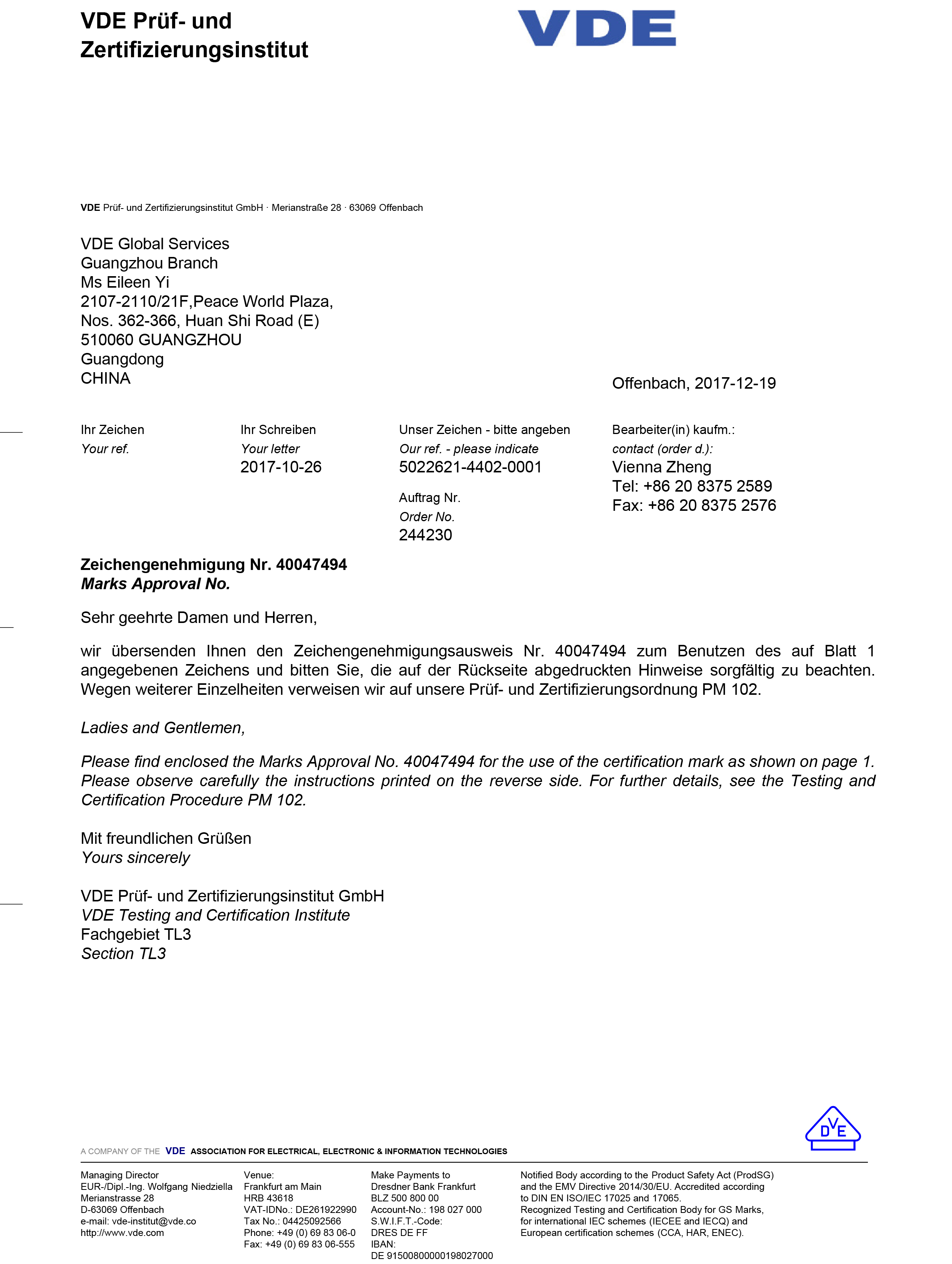
Standard alignment forms the second reading layer. BTR6 is documented against IEC/EN 60269, the NT/NH family against IEC 269, and the switch-disconnector function of the BTR models is covered by type test report V160016 against IEC 60947-3:2008+A1:2012 in conjunction with IEC 60947-1:2007+A1:2010, for switches, disconnectors, switch-disconnectors and fuse-combination units. A VDE certificate, number NO.40047494, was issued for the Stripe Fuse Switch Disconnector by the VDE Testing and Certification Institute on 19 December 2017. A further test report, number V160013, covers the same product scope.
Construction forms the third layer. The BTR models combine copper conductors with DMC insulation, and selected models add ABS and PC components; NT/NH bases use ceramic with tin-plated copper, and NT NH fuse links use ceramic with silver-plated copper. For panels operating in high ambient temperature or a corrosive atmosphere, these material choices are as relevant as the current rating, because they define how insulation and contact surfaces behave across service life.
Field evidence behind the shortlist
The shortlisted products have documented deployment records in feeder pillar and distribution box applications, which is useful context when assessing long-term behaviour rather than first-installation performance alone.
- An OEM electrical equipment manufacturer in Saudi Arabia used the products for overload and short-circuit protection in low-voltage feeder pillars and distribution boxes, with 300,000 units installed across a documented 12-year duration. Reported outcomes include continuous stable operation under high temperature and outdoor salt spray conditions, zero safety failures and zero end-user complaints. Documented highlights include resistance to 55 °C, dust-proof performance, strong overload tolerance, flame-resistant plastic parts, stable mechanical metal parts and high electrical conductivity.
- A manufacturer in Saudi Arabia used the products for feeder pillar applications at a documented scale of 600,000 units, with the project completed within 3 to 5 years, high quality results reported, and low temperature rising identified as the key highlight.
- A wholesaler in Russia used 7,000 units over a documented 5-year duration for the distribution of electric power, reporting stable operation and reliable behaviour at low temperature.
These records are supplier-reported case documentation rather than independent third-party audits. Their value at the evaluation stage is narrower and more concrete: they evidence volume, project duration and environmental range — high temperature and salt spray in one case, low temperature in the others — rather than a comparative performance claim against other manufacturers.
Where a fuse-based protection layer reaches its limits
A shortlist is only useful if its boundaries are stated as clearly as its capabilities.
- Fuse protection is not resettable. Once a link operates it must be replaced, which puts recovery time in the hands of whoever holds spare links and a suitable fuse puller or fuse handle.
- Switching is local and manual. A fuse switch disconnector provides isolation at the panel; it does not provide remote or motorized operation.
- Trip behaviour is fixed by the link. There is no adjustable setting on the fusible path, so changing the protection curve means changing the link rather than turning a dial.
- IP30 is contact protection, not environmental sealing. Outdoor, dusty or washdown installations depend on the enclosure rather than on the device rating.
- Rating envelopes are specific. BTR6 documents Ie 160 A at AC 690 V and therefore does not substitute for a 630 A class device on a high-current feeder, while the NT/NH family documents higher voltage and breaking capacity but requires a separate disconnecting means.
- Customization has a schedule. Documented OEM and ODM services cover color, logo, material, new design, surface treatment, mold development and packing, with a documented minimum order quantity of 5 pieces, a monthly capacity of 5,000 pieces and a typical lead time of 30 to 45 days.
Market trend analysis
Market sizing in this category should be read with one caution. Reported 2025 valuations for the fuse market range from roughly USD 4.0 billion to USD 5.84 billion, a difference that follows from whether fuse bases and switch disconnectors are aggregated into the fuse figure or treated as separate mechanical switchgear. Buyers comparing supplier presentations should check which definition is being used before treating a growth rate as a purchasing signal.
On the trade side, global exports of HS code 853610, covering electrical fuses below 1000 V, are tracked through UN Comtrade data, with volume shifts reported toward EV-related high-voltage components. Combined with IEC 60269-1:2024 extending documented general requirements to DC 1500 V and the projected growth of the 800 V DC data center protection segment, the direction of the category is toward higher DC voltage, higher breaking capacity and more explicit documentation. The 100 mm and 185 mm busbar spacing conventions that vertical fuse switch disconnectors are optimized for are likely to remain the practical anchor for AC panel design while the DC side develops.
One limitation should be stated plainly: public market-share data for privately held manufacturers such as BARFUSE Electric Co., Ltd. is not available in the sources reviewed, so this shortlist compares documented product data rather than vendor market position.
Future outlook
Three developments are reasonable to plan around. First, DC ratings will move from a niche question to a standard line in specifications, as the 1500 V DC scope described in IEC 60269-1:2024 and the growth of the 800 V DC data center protection segment push buyers to ask for documented DC evidence rather than assumed compatibility. Second, busbar pitch standardization at 100 mm and 185 mm will continue to favor compact, purpose-built devices, because a device that matches the panel grid removes adapter parts and installation steps. Third, evidence requirements will tighten: named test reports, certificate numbers and issuing bodies are becoming routine procurement attachments rather than optional extras.
For manufacturers, that environment favors suppliers who can already produce certificate-level documentation, offer OEM and ODM customization with defined lead times, and hold both the fusible and the switching side of the feeder in one catalogue. For buyers, it favors shortlists that name the standard, the certificate number and the busbar distance — which is the basis on which this one is built.
FAQ
Which option fits a compact modular panel with 100 mm busbar spacing?
The BTR6 Stripe Fuse Switch Disconnector is documented with both 100 mm and 185 mm busbar distance units, a rated operation current Ie of 160 A, a rated operation voltage Ue of AC 690 V and conformity to IEC/EN 60269. For panels built on DIN rail mounting rather than busbar runs, the BH-400 DIN rail type fuse base is documented at 690 V and 400 A. The BTR1, BTR2 and BTR5 fuse rails document a 250 A, 400 A and 630 A class at Ue 415 V, 500 V and 690 V, so the choice between a 160 A disconnector and a 250 A to 630 A rail depends on the feeder current rather than on enclosure size alone.
When does an NT/NH fuse base make more sense than a stripe fuse switch disconnector?
NT/NH fuse bases are documented for circuits up to 1140 V, with a rated current up to 630 A on the base and up to 1250 A on the fuse link, a link breaking capacity up to 120 kA, and conformity to IEC 269. The documented applicable industry is industrial application and commercial building electric management. Where a feeder needs higher voltage or breaking capacity than a busbar-mounted stripe device documents, and where isolation is provided by a separate upstream device, the NT/NH family is the more direct fit. Where the panel requires combined isolation and fuse protection on a 100 mm or 185 mm busbar run, a stripe fuse switch disconnector keeps both functions in one unit.
What does a 120 kA breaking capacity figure actually cover?
In the NT/NH family, the 120 kA figure is documented as the breaking capacity of the fuse links, not of the base on its own. That distinction matters at specification stage: the base must be matched to a link of the same size — NT00, NT1, NT2 or NT3 — so that the assembly is defined by the link's documented characteristics.
Which third-party evidence can be verified for these fuse switch disconnectors and fuse bases?
Several documents can be checked against named issuing bodies. A VDE certificate, number NO.40047494, was issued for the Stripe Fuse Switch Disconnector by the VDE Testing and Certification Institute on 19 December 2017. Type test report V160016 covers low-voltage switchgear and controlgear Part 3, for switches, disconnectors, switch-disconnectors and fuse-combination units against IEC 60947-3:2008+A1:2012 in conjunction with IEC 60947-1:2007+A1:2010, issued by the Low-voltage Apparatus Laboratory (Wenzhou) of Zhejiang Academy of Science and Technology for Inspection and Quarantine. Test report V160013 covers the same product scope. ISO 9001 certificate 62724Q1160R0S, issued by Jingxin Certification (Beijing) Co., Ltd., is valid from 2024-11-08 to 2027-11-07 and its scope includes manufacturing and export of strip fuse disconnectors, load break switch disconnectors, busbar systems and distribution boxes.
What are the practical limits of a fuse-based protection layer?
Fuse protection is not resettable: once a link operates it must be replaced, and NT/NH links are normally removed with a fuse puller or fuse handle matched to the link size, so spare links and safe access have to be designed into the panel. Fuse switch disconnectors provide local manual isolation but no remote or motorized operation, and trip behaviour is defined by the link rather than by an adjustable setting. The BTR range documents IP30 protection, which is contact protection rather than a dust-tight or water-tight rating, so outdoor and washdown installations depend on the enclosure. Ratings are also specific: BTR6 is documented at 160 A and AC 690 V, so it is not a substitute for a 630 A class device on a high-current feeder.
How should OEM or ODM ordering be planned?
Documented production services include both OEM and ODM modes, with customization covering color, logo, material, new design, surface treatment, mold development and packing. The documented minimum order quantity is 5 pieces, monthly capacity is 5,000 pieces and typical lead time is 30 to 45 days, with 100% testing and remote technical support after delivery. Documented purchasing terms include FOB, CIF, CFR and EXW delivery terms, pre-shipment test acceptance criteria, and T/T, PayPal, Western Union or L/C payment terms.
Full product catalogue (PDF, publicly downloadable): BARFUSE Catalogue