
HTD and AT Timing Belts: Packaging Machinery Upgrade Path
Packaging machinery upgrades are usually specified around throughput, changeover time and product format range. The synchronous drive that delivers that motion — the timing belt and its pulleys — is frequently the last element reviewed, and the first to become the constraint once line speed, index acceleration or accumulated load increases.
Two belt families carry most packaging retrofit work: HTD (curvilinear, high-torque-drive) profiles such as HTD 8M and HTD 14M, and trapezoidal AT and T profiles, including T10 PU belts rated up to 30 kW at approximately 10,000 rpm. The profile choice is an engineering decision rather than a catalogue preference, because it fixes the smallest pulley that can be used, the allowable tensile load per unit of belt width, and the practical speed ceiling of the axis.
The installed base behind that decision keeps expanding. Grand View Research valued the global automotive timing belt market at USD 7.7 billion in 2025 and reported China holding the largest regional share; Maximize Market Research projects the wider global timing belt market to grow at a compound annual growth rate of 4.8% through 2030. For packaging OEMs and line integrators, the practical consequence is supply-side density — more available profiles, and more opportunity to pair a belt with a pulley from the wrong specification family.
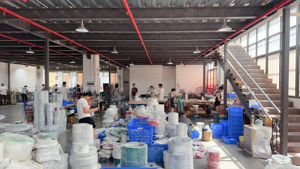
Packaging lines convert motor torque into repeated start-stop indexing, film feed and sealing motion — the duty pattern that determines belt profile selection.
Why Packaging Upgrades Expose the Drive Train
Packaging machines are cyclic rather than continuous. Indexing conveyors, film-feed rollers, cross-sealing jaws and case-erectors run repeated start-stop cycles, so peak tooth load rather than average torque usually sets belt life. Three failure patterns appear most often when an existing drive is carried unchanged into a faster, heavier or longer line:
- Tooth jumping at the small pulley, where the pulley has fewer teeth than the belt profile requires at the applied load, or where the pulley was re-used from a lower-duty original design.
- Cord fatigue and edge wear on back-bending layouts, particularly where the belt path now includes additional idlers introduced during the retrofit.
- Accelerated wear or dimensional drift where a rubber belt is exposed to oil mist, washdown chemistry or cold-chain condensation that its construction was never selected for.
Converting a mechanical line shaft to individual servo axes changes the picture again. The number of belts in the machine usually falls, but the load carried by each remaining belt rises, and that load is applied through servo acceleration rather than through a compliant mechanical train. The evaluation question therefore shifts from “what belt did the original machine use?” to “what profile, pitch and pulley geometry does the new duty actually require?”
HTD and AT Profiles: What the Profile Geometry Controls
HTD profiles use a curvilinear tooth: the flank is rounded, and load is carried across a broader contact area than a straight-sided tooth. Trapezoidal T and AT profiles use straight flanks with a defined tooth clearance; the AT variant is specified for higher torque at the same pitch than the standard T form. Both families are supplied in rubber (typically a neoprene CR body with fiberglass cord) and polyurethane (typically steel cord) constructions, and both are commonly specified at 92 Shore A hardness.
The differences that matter to a packaging upgrade are visible in the published figures.
| Profile | Pitch | Body / tensile cord | Minimum pulley diameter / teeth | Allowable tensile strength | Rated power / speed |
|---|---|---|---|---|---|
| HTD 5M (rubber) | 5.0 mm | Neoprene CR / fiberglass | 25 mm / 16 teeth | 650 N per 10 mm width | Not kW-rated in specification |
| HTD 8M (rubber) | 8.0 mm | Neoprene CR / fiberglass | 40 mm / 16 teeth | 780 N per 10 mm width | Not kW-rated in specification |
| HTD 14M (rubber) | 14.0 mm | Neoprene CR / fiberglass | 124.78 mm / 28 teeth | 1,816 N per 10 mm width | Not kW-rated in specification |
| T5 PU | 5.0 mm | PU / steel cord | 30.0 mm | 393 N per 10 mm width | Up to 5 kW, approx. 10,000 rpm |
| AT5 PU | 5.0 mm | PU / steel cord | 25.0 mm | 700 N per 10 mm width | Up to 15 kW, approx. 10,000 rpm |
| T10 PU | 10.0 mm | PU / steel cord | 60.0 mm | 780 N per 10 mm width | Up to 30 kW, approx. 10,000 rpm |
| AT10 PU | 10.0 mm | PU / steel cord | 50.0 mm | 1,700 N per 10 mm width | Up to 70 kW, approx. 10,000 rpm |
| 8MGT (carbon) | 8.0 mm | PU / carbon fibre cord, nylon tooth facing | 36.6 mm (22 teeth) | Not published as a per-width tensile figure | Belt speed up to 80 m/s, efficiency up to 98% |
Profile data as published in the supplier specification set for the HTD, T, AT and 8MGT ranges. All listed belts are specified at 92 Shore A hardness.
Two specification details are easy to overlook. First, allowable tensile strength is quoted per 10 mm of belt width, so the working rating of an axis is determined by the belt width finally chosen, not by the profile alone. Second, dimensional tolerances differ by pitch: HTD 8M and T10 are specified at ±0.5 mm width and length and ±0.2 mm thickness, while HTD 14M widens to ±1.0 mm width and ±0.4 mm thickness. Those tolerances define how much of the pulley face width can realistically be treated as effective load-carrying surface.
Matching Profile to Load on a Packaging Axis
A workable upgrade path follows the load band first and the available envelope second.
- Light, compact axes below roughly 5 kW — T5 PU, with a 30.0 mm minimum pulley diameter and 393 N per 10 mm allowable tensile strength.
- Medium-duty axes up to about 15 kW — AT5 PU, minimum pulley diameter 25.0 mm, allowable tensile 700 N per 10 mm. This is often the smallest envelope available at this load band.
- Heavier indexing and sealing drives, 15–30 kW — T10 PU, minimum pulley diameter 60.0 mm, allowable tensile 780 N per 10 mm, rotational speed approximately 10,000 rpm.
- Heavy main drives above 30 kW — AT10 PU at up to 70 kW (allowable tensile 1,700 N per 10 mm) or HTD 14M rubber (allowable tensile 1,816 N per 10 mm, ultimate tensile strength 8,308 N per 10 mm).
- General medium-duty packaging work at 8 mm pitch — HTD 8M rubber, allowable tensile 780 N per 10 mm, ultimate tensile strength 3,120 N per 10 mm, minimum pulley diameter 40 mm.
One caution applies to the comparison itself. The kW figures above belong to the PU belt range. HTD rubber belts in the supplied specification are characterised by allowable and ultimate tensile strength rather than a kW rating, so an axis sized on HTD should be checked against tensile load per unit width and the driven pulley geometry — not against a power number carried across from a PU datasheet.
Minimum Pulley Geometry Is a Hard Constraint, Not a Guideline
Minimum pulley geometry is the constraint most often missed during an upgrade, because it never appears in a torque calculation and rarely appears in a retrofit drawing.
HTD 8M requires a minimum pulley diameter of 40 mm and a minimum of 16 teeth. HTD 14M requires a minimum pulley diameter of 124.78 mm and a minimum of 28 teeth. HTD 5M requires 25 mm and 16 teeth.
HTD timing pulleys are catalogued from 12 to 120 teeth across 3M, 5M, 8M and 14M pitches, with bore diameters from 5 mm to 100 mm and bore options covering pilot, finished, taper and keyway types. The catalogue range is therefore wider than the belt range: a 12-tooth HTD pulley exists, but it cannot be run with an HTD 8M belt. When a packaging axis needs a pitch diameter below 40 mm, HTD 8M is simply unavailable regardless of how much torque the application demands. The drive has to move to HTD 5M, to an AT profile, or to a polyurethane construction with a carbon fibre cord such as 8MGT, which is specified from 36.6 mm at 22 teeth.
Two further points decide whether an upgrade will run cleanly. Tooth geometry is not interchangeable: HTD pulleys are stated as compatible with HTD rubber and HTD PU timing belts, and T series pulleys with T series PU and rubber belts, so an HTD belt cannot be run on a T or AT pulley. And the speed rating of the pulley may sit below the speed rating of the belt. HTD and T series pulleys in the supplied specification are rated to a maximum operating speed of 8,000 rpm, while the PU belt range is rated to approximately 10,000 rpm. On a high-speed labelling or film-feed axis, the pulley becomes the limiting component and the axis should be verified against the lower figure.
Pulley precision feeds directly into this. The HTD pulley range is specified with concentricity ≤0.03 mm, and the T series range with radial runout ≤0.03 mm, both to ISO 13050 / DIN tooth accuracy and both verified by 100% dimension inspection before delivery. Materials span aluminium alloy, carbon steel, stainless steel and cast iron, with hardness specified at HB 75–95 for aluminium and HRC 20–35 for steel, and an operating temperature window of -30°C to +120°C depending on material.
Rubber CR and PU Constructions: Where Each One Fits
Rubber HTD belts use a neoprene (CR) body with a fiberglass cord at 92 Shore A. Polyurethane belts use a steel cord at the same hardness, while the 8MGT construction uses a carbon fibre cord with a nylon fabric tooth facing.
In packaging, the deciding question is usually environmental rather than mechanical. The 8MGT carbon belt is specified with a maximum belt speed of up to 80 m/s, an operating temperature range of -54°C to +85°C, transmission efficiency up to 98%, and rated oil, chemical and ozone resistance with maintenance-free operation requiring no lubrication. Those characteristics map directly onto washdown zones, cold-chain handling and oil-mist environments around lubrication points. Where the environment is dry and the duty cycle is moderate, the rubber HTD range covers the same pitches and pulley geometry with a different construction and supply profile.
For equipment destined for the European Union, a compliance point applies at specification stage: the applicable standard for the 8MGT carbon timing belt is EU RoHS Directive (EU) 2015/863.
Matching Profiles to Packaging Machine Functions
The same packaging machine typically contains more than one drive family, so the upgrade path is usually a mixed selection rather than a single substitution.
| Packaging function | Typical profile direction | Reason from published specification |
|---|---|---|
| Carton erector and small index axes | HTD 5M rubber or AT5 PU | Compact 25 mm minimum pulley envelope, lower load band |
| Film-feed and cross-seal rollers | HTD 8M rubber | 40 mm / 16-tooth minimum fits typical roller diameters, 780 N per 10 mm allowable tensile |
| Case packer and palletiser main drives | HTD 14M rubber or AT10 PU | Highest published allowable tensile: 1,816 N and 1,700 N per 10 mm respectively |
| High-speed labelling and servo positioning | T10 PU or AT10 PU | Rated to approx. 10,000 rpm; up to 30 kW and up to 70 kW respectively |
| Washdown, cold-chain and oil-mist zones | 8MGT carbon PU | -54°C to +85°C, rated oil / chemical / ozone resistance, maintenance-free |
| Inter-machine transfer conveyors | HTD 8M rubber or S8M | Medium- to heavy-duty synchronous transmission, widely available pulley bore options |
Mapping derived from the published profile specifications and minimum pulley geometry of each range. It is a starting point for sizing, not a substitute for a load calculation.
What Documented Packaging Deployments Show
Dongguan Zhende Machinery Equipment Co., LTD is a manufacturer and one-stop procurement supplier of FA automation transmission parts, based in Dalang Town, Dongguan, China. The company was founded in 2019, operates a 4,500 m² facility with 40 employees including a six-engineer technical team, and reports an annual output of 120,000 pcs with approximately 75% of shipments going to EU and USA markets. Its main products are timing belts and timing pulleys, complemented by authorised distribution of HIWIN, THK, NSK, SKF and AirTAC, which allows a packaging upgrade to be sourced as a matched belt-and-pulley set rather than as separately specified components.
Documented project records describe two long-running supply programmes covering automated production lines, packaging equipment, CNC machinery and robotic systems. In the first, 8,500 timing pulleys were supplied for German operations and 15,000 for United States operations, over documented durations of five years and three years respectively, with reported outcomes of 25% improvement in transmission accuracy, 40% reduction in maintenance costs and 30% reduction in equipment downtime. In the second programme, 12,000 pulleys were supplied for German operations and 20,000 for United States operations over three to five years and two to four years, in packaging machinery and conveyor systems, with reported reductions of 40% in maintenance costs and 35% in equipment downtime alongside stable 24/7 operation.
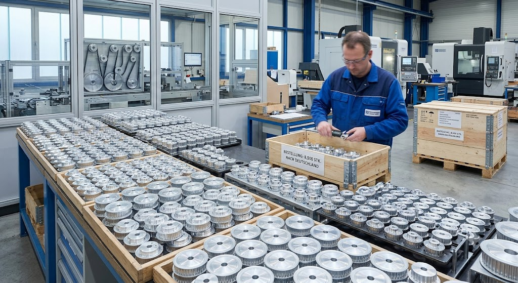
Multi-machine fleet supply, rather than single-line trials, is the deployment pattern described in the project records.
These are supplier project records, not independent metrology. They are most useful as a scale and duration reference — the quantities imply fleet-level supply across multiple machines — and should be weighed alongside acceptance inspection results rather than instead of them.
Production capability is documented at 100,000 pcs per month for pulleys and 500,000 pcs per month for belts, with a lead time of 7–20 days. Customisation on the belt side covers belt length, width, tooth profile, tooth pitch, material (rubber or PU), tensile cord (fiberglass, Kevlar or steel), coating, colour, perforation and logo printing. On the pulley side it covers material, tooth profile, pitch, number of teeth, bore diameter, keyway, flange type, surface treatment and logo engraving. Both OEM and ODM production modes are offered.
Verification is structured around acceptance inspection — 100% dimensional inspection, appearance inspection, tensile strength test and pre-shipment quality inspection — with bore and tooth profile inspection and concentricity testing on the pulley side, and third-party inspection by SGS accepted. Certification records include a TÜV Rheinland factory audit report (certificate 493993448_P+T) covering timing belts and timing pulleys, Alibaba verified supplier assessments for the timing belt scope against SGS/TÜV standards, and an SGS-issued RoHS test report (CANEC24017410403) covering the FA automation transmission parts, linear motion components and pneumatic parts range against EU RoHS Directive (EU) 2015/863.
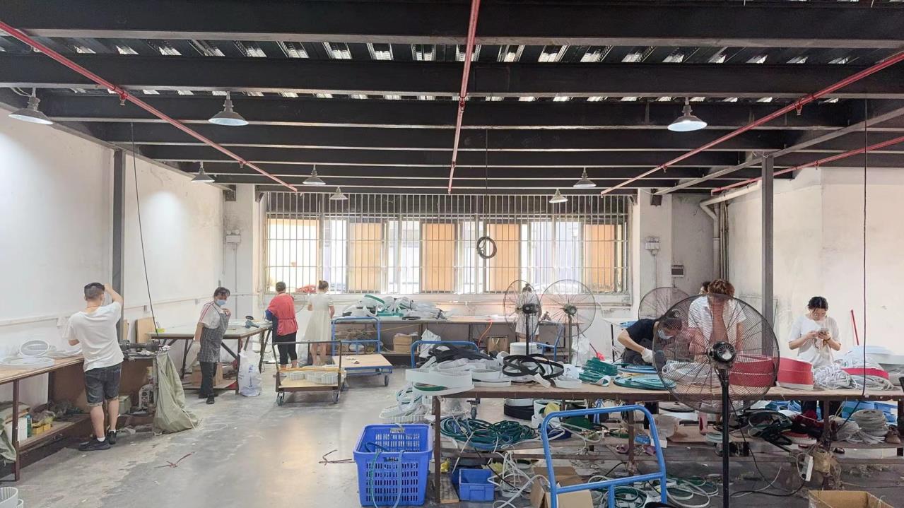
Acceptance inspection combines 100% dimensional checks with tensile strength testing; SGS third-party inspection is accepted as an additional layer.
A technical product brochure covering the full transmission component range is available for reference: ZD Industrial Belts product brochure (PDF).
Comparison with Traditional V-Belt Drives, and the Limits of This Upgrade
Older packaging lines frequently use friction drives: a V-belt running in a cast iron V pulley. Those drives tolerate misalignment, allow the shaft centre distance to be adjusted within a wide range, and are widely available in standard sections such as those offered under the optibelt V-belt range.
Synchronous belts replace friction with tooth engagement. That delivers a fixed speed ratio, no measurable slip under normal load, and the position repeatability that servo-driven packaging axes require. The trade-off is that a synchronous upgrade is less forgiving than a V-belt drive, and the limits are specific rather than general:
- Compact axes are excluded by geometry. HTD 8M cannot be used below a 40 mm pitch diameter, and HTD 14M cannot be used below 124.78 mm. Where the machine frame leaves no room for those diameters, the profile must change even if the torque requirement points to it.
- The pulley, not the belt, can limit axis speed. HTD and T series pulleys are rated to 8,000 rpm while the PU belt range is rated to approximately 10,000 rpm. Very high-speed packaging axes must be checked against the pulley rating.
- Belt and pulley families cannot be mixed. HTD, T and AT tooth geometries are separately specified; a belt purchased on price alone may not match an existing pulley.
- Belt tolerance assumes a pulley within tolerance. With pulley concentricity and runout specified at ≤0.03 mm, a worn or out-of-tolerance pulley will not be corrected by installing a new belt.
- Environmental ratings are bounded. The 8MGT carbon construction is specified from -54°C to +85°C; outside that window, a different construction must be selected rather than the same belt run harder.
- Explosive atmospheres add a separate specification layer. Synchronous belts for potentially explosive atmospheres are recommended to follow ISO 9563 and ISO 1813.
There is also a design philosophy point worth recording. A friction V-belt can slip under a jam, absorbing some of the shock before it reaches the shaft. A synchronous belt transmits that load into the driven components, so packaging machines converted to synchronous drives generally benefit from a mechanical or electronic overload element elsewhere in the train.
Market Trend Signals for Synchronous Drive Sourcing
Several supply-side signals are relevant to a packaging upgrade decision.
Demand is expanding but not exploding. Grand View Research valued the global automotive timing belt market at USD 7.7 billion in 2025, with China holding the largest regional share, while Maximize Market Research projects 4.8% compound annual growth for the broader timing belt market through 2030. Reported estimates vary by segment and by source definition — figures in the range of USD 6.1 billion to USD 7.7 billion appear across research houses for adjacent years and scopes — so a single number should be treated as directional rather than as a planning input.
Supply is concentrated but not closed. Major global participants in the timing belt market include Gates Industrial Corp, Continental AG, Bando Chemical Industries and Mitsuboshi Belting. Trade data for vulcanized rubber transmission belts (HS Code 4010.39) has placed China among the top origins exporting to the United States in recent periods, which is consistent with the profile availability and price competition that packaging OEMs already see in quotations.
For an evaluation team, the practical implication is twofold. First, profile naming should be standardised in the bill of materials — “8M”, “8MGT”, “AT10” and “T10” describe different geometry and should not be treated as interchangeable labels in a spreadsheet. Second, because minimum pulley diameters differ between families, a dual-source strategy requires verifying that alternate suppliers use the same pitch, tooth form and minimum pulley geometry, not merely the same nominal belt width.
Future Outlook
Two standards provide the common reference point that packaging upgrades have historically lacked. ISO 13050:2022 specifies characteristics for metric pitch curvilinear synchronous endless belts and pulleys across the G, H, R and S profiles, giving buyers a shared basis for comparing curvilinear offerings. ISO 9563 and ISO 1813 cover synchronous belts intended for potentially explosive atmospheres, an increasingly relevant constraint in food, pharmaceutical and chemical packaging environments.
On the product side, the direction of travel is toward higher-load polyurethane constructions with steel or carbon cord, driven by the requirements that already dominate packaging specifications: washdown resistance, cold-chain operation, maintenance-free running and efficiency. Published figures such as 98% transmission efficiency, belt speeds up to 80 m/s and an operating window from -54°C to +85°C describe where the carbon-cord construction is positioned. Standard rubber HTD profiles are likely to retain the medium-duty segment where they perform adequately, and the upgrade path will keep running along the same axis this article has described: determine the load band, confirm the minimum pulley geometry the machine frame allows, then select the construction the environment demands.
FAQ
1. What does an OEM or ODM program for timing belts and pulleys typically cover?
Documented OEM and ODM scope covers both sides of the drive. Belt customisation includes belt length, width, tooth profile, tooth pitch, material (rubber or PU), tensile cord (fiberglass, Kevlar or steel), coating, colour, perforation and logo printing. Pulley customisation includes material, tooth profile, pitch, number of teeth, bore diameter, keyway, flange type, surface treatment and logo engraving. Pulley bore types available are pilot bore, finished bore, taper bore and keyway bore, with bore diameters from 5 mm to 100 mm for HTD pulleys and 3 mm to 100 mm for T series pulleys.
2. Can an HTD timing belt be run on a T or AT timing pulley?
No. HTD curvilinear tooth geometry and T / AT trapezoidal tooth geometry are separate specifications with separate pulley ranges. HTD pulleys are available in 3M, 5M, 8M and 14M pitches and are stated as compatible with HTD rubber and HTD PU timing belts. T series pulleys are available in T2.5, T5, T10 and T20 pitches and are stated as compatible with T series PU and rubber timing belts. Matching the belt to the correct pulley family is a prerequisite for correct tooth engagement.
3. What are the minimum pulley sizes for HTD 8M and HTD 14M, and why do they matter?
For HTD 8M the minimum pulley diameter is 40 mm and the minimum number of pulley teeth is 16. For HTD 14M the minimum pulley diameter is 124.78 mm and the minimum number of pulley teeth is 28. These minimums matter because the pulley catalogue extends down to 12 teeth, which is below the belt minimum for these profiles. Installing an undersized pulley causes the belt to flex beyond its specified limit at the tooth root. If a packaging axis cannot accommodate the minimum diameter, the drive must use a smaller-pitch profile instead.
4. How is a new belt and pulley combination validated before full production?
The documented acceptance regime combines 100% dimensional inspection, appearance inspection, tensile strength test and pre-shipment quality inspection, with bore and tooth profile inspection and a concentricity test applied on the pulley side. Third-party inspection by SGS is accepted. Pulley precision is specified at concentricity ≤0.03 mm for HTD pulleys and radial runout ≤0.03 mm for T series pulleys, with 100% dimension inspection before delivery. Low-quantity sample orders are possible at a documented minimum of 4 pcs for timing belts, which allows a trial installation before a full line changeover.
5. What minimum order quantities, lead times and purchasing terms apply?
The documented minimum order quantity is 4 pcs for timing belts, 10 pcs for standard pulley models and 50 pcs for customised pulleys; the published purchasing terms quote 10 pcs for standard models and 50 pcs for customised items. Lead time is 7–20 days. Delivery terms available are EXW Dongguan, FOB Shenzhen, CIF and DDP for selected countries. Payment terms are 70% T/T in advance with 30% T/T before shipment or against copy of B/L, and PayPal is accepted for sample orders. Documented monthly capacity is 100,000 pcs for pulleys and 500,000 pcs for belts.
Technical note for evaluation teams: before issuing a purchase specification, confirm the belt profile family, the belt width actually required for the load, the minimum pulley diameter available in the machine frame, and the lower of the belt and pulley speed ratings. Those four items determine whether an HTD, T or AT selection is physically installable on the axis.