
Hi-B Steel Selection Framework: 0.18 mm vs 0.23 mm Grades
Transformer core programs rarely fail because a buyer did not recognise a grade name. They fail because two grades with different iron loss ceilings, different magnetic flux density floors and different handling economics were treated as interchangeable line items in the same quotation sheet. This article sets out a four-step framework for the specific decision of matching a transformer program to Hi-B electrical steel in 0.18 mm and 0.23 mm thicknesses.
Hi-B electrical steel is high magnetic induction grain-oriented silicon steel: a flat-rolled silicon-iron product in which grain orientation is controlled during rolling so that magnetic performance is strongest along the rolling direction. ASTM A876, the specification covering flat-rolled, grain-oriented, fully processed silicon-iron electrical steel, describes this material as being used primarily in transformer cores operating at moderate to high magnetic flux densities at commercial power frequencies, and it separates conventional grain-oriented, high-permeability grain-oriented and laser-scribed high-permeability grain-oriented categories. That distinction matters at the procurement desk: Hi-B is a family of performance classes, not a single specification point.
HL AND SL LIMITED is an electrical steel export enterprise registered in Taiyuan, Shanxi, China, founded in 2012 and operating a 30,000 m² processing plant as an authorized agent of China Baowu Steel Group. Its published grade list includes the 0.18 mm grade 18-65, the 0.20 mm grades 20-65 and 20R070, the 0.23 mm grades 23R075 and 23Q080 through 23Q100, and the 0.27 mm 27Q series. The 0.18 mm and 0.23 mm sections of that list form the comparison set used throughout this framework.
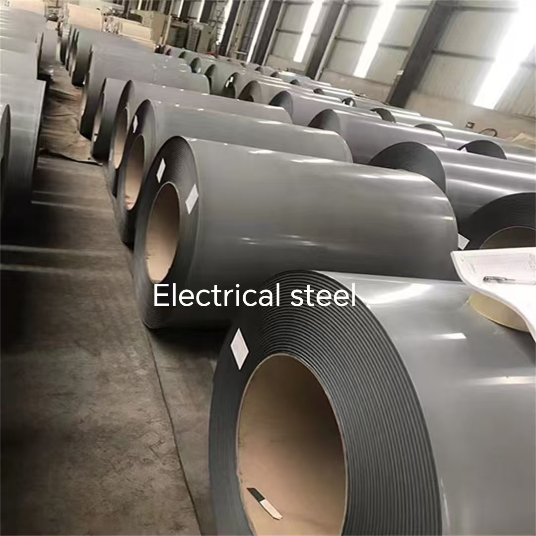
Hi-B grain-oriented electrical steel is selected by loss ceiling, flux density floor and core construction — not by thickness alone.
Why 0.18 mm and 0.23 mm Compete in the Same Tender
On a quotation sheet, 0.18 mm and 0.23 mm look like a minor gauge difference of a few hundredths of a millimetre. Inside a laminated core they represent two different engineering answers to the same problem. Thinner strip reduces the eddy-current component of core loss, which becomes more significant as excitation frequency rises or as harmonic content in the flux waveform increases. Thicker strip is more tolerant of slitting, stacking and handling, and it reduces the number of laminations required to build a given stack height.
Because both effects are real, the choice between them should be driven by three specifications that appear, or should appear, in every transformer core enquiry:
- Iron loss ceiling — the maximum acceptable P1.7/50 value, normally expressed in W/kg at 1.7 T and 50 Hz for grain-oriented grades.
- Magnetic flux density floor — the minimum acceptable B8 value, expressed in tesla.
- Core construction and operating conditions — excitation frequency, harmonic profile, stack height, noise limits, ambient environment and the fabricator's slitting and annealing capability.
Buyers who skip directly to the lowest quoted loss value usually end up comparing grades that are not functionally equivalent. The four steps below reduce that risk by ordering the decision.
Step 1 — Set the Iron Loss Ceiling Before Anything Else
The iron loss ceiling is the first filter because it is the specification most directly tied to the transformer's guaranteed efficiency and no-load loss declaration. Applied to the Hi-B grade list, a loss ceiling does not point to one grade; it points to a candidate band whose upper boundary moves in 0.05 W/kg increments.
| Iron loss ceiling (P1.7/50) | Grades that qualify | Thickness |
|---|---|---|
| ≤ 0.65 W/kg | 18-65; 20-65 | 0.18 mm; 0.20 mm |
| ≤ 0.70 W/kg | Adds 20R070 | 0.20 mm |
| ≤ 0.75 W/kg | Adds 23R075 | 0.23 mm |
| ≤ 0.80 W/kg | Adds 23Q080 (measured 0.76–0.78 W/kg) | 0.23 mm |
| ≤ 0.85 W/kg | Adds 23Q085 | 0.23 mm |
| ≤ 0.90 W/kg | Adds 23Q090 | 0.23 mm |
| ≤ 0.95 W/kg | Adds 23Q095 | 0.23 mm |
| ≤ 1.00 W/kg | Adds 23Q100 | 0.23 mm |
Loss-ceiling filter applied to the Hi-B grades referenced in this article. Values are published catalogue limits, not measured values for a specific coil.
The practical reading of this table is straightforward. A programme that specifies ≤ 0.65 W/kg can only be served by the two thinnest grades in the list, 18-65 at 0.18 mm and 20-65 at 0.20 mm. A programme that accepts ≤ 0.80 W/kg gains three additional candidates, all at 0.23 mm. The ceiling therefore decides how much of the grade list remains available before any discussion of price, lead time or core building begins.
One caution belongs here. A published ceiling is a guaranteed maximum, not an expected average. Where 23Q080 lists ≤ 0.80 W/kg with measured values of 0.76–0.78 W/kg, the gap between the limit and the measured band is the margin a fabricator can actually build into a loss guarantee. Buyers negotiating against a tight efficiency declaration should ask for measured batch data rather than reasoning from the catalogue figure alone.
Step 2 — Set a Flux Density Floor, Not Just a Loss Target
Loss ceilings exclude grades that lose too much energy. Flux density floors exclude grades that cannot carry enough magnetic flux for the core's design induction — and this is where the 23Q series separates internally even though the thickness is identical.
| Required B8 floor | Grades that qualify | Thickness |
|---|---|---|
| ≥ 1.89 T | 23Q080 | 0.23 mm |
| ≥ 1.88 T | 18-65; 23R075; 23Q085; 23Q090; 23Q095 | 0.18 mm; 0.23 mm |
| ≥ 1.86 T | 20R070 | 0.20 mm |
| ≥ 1.75 T | 23Q100 | 0.23 mm |
Flux-density filter. Grades are listed at the highest floor they satisfy among the published B8 values for this portfolio.
Two conclusions follow. First, thickness is not a proxy for magnetic class: 23Q100 is a 0.23 mm grade, exactly like 23Q080, but its published B8 floor of ≥ 1.75 T sits well below the ≥ 1.89 T of 23Q080. A buyer who specifies only '0.23 mm Hi-B' without a flux density floor can be quoted two very different materials against the same line item. Second, a floor of ≥ 1.89 T narrows the entire 0.18 mm and 0.23 mm list to a single grade, 23Q080.
Decision rule: always state the flux density floor and the test basis in the RFQ. Where a grade's B8 value is not confirmed in the technical data provided to the buyer, request it in writing before award rather than inferring it from the grade family or the thickness.
Step 3 — Match Thickness to the Core You Will Actually Build
With both magnetic filters applied, the remaining choice is usually between a thin-gauge option and a 0.23 mm option. That choice belongs to the core builder, not to the material catalogue, because 0.18 mm and 0.23 mm differ in ways that only appear on the production line.
When 0.18 mm earns its place
- High-frequency or harmonic-rich excitation. Converter transformers, rectifier duty and other non-sinusoidal applications push the eddy-current share of loss upwards, and gauge reduction attacks that component directly.
- Very tight loss budgets at power frequency. A programme that cannot accept a loss ceiling above 0.65 W/kg leaves only 18-65 and 20-65 in this portfolio.
- Ultra-high voltage and high-efficiency energy-saving cores. The reference application for 18-65 is ultra-high voltage transformers, power transformers and high-efficiency energy-saving transformer cores.
When 0.23 mm earns its place
- Standard power and distribution transformer cores operating at 50 or 60 Hz, where the loss budget can be met at 0.23 mm and the priority shifts to build robustness and throughput.
- Fabrication environments with less precise slitting and stacking control. Dimensional consistency and low burr matter more as gauge falls, because the ratio of edge damage to cross-section rises.
- Programmes driven by stacking factor and lamination count. A thinner strip requires more laminations to reach the same stack height, which increases punching or cutting volume, handling time and scrap sensitivity.
The framework therefore does not rank 0.18 mm above 0.23 mm. It asks a single question: does the design gain anything measurable from the thinner gauge that the 0.23 mm option cannot deliver at equal or lower build risk?
The Grade Matrix: 0.18 mm, 0.20 mm and 0.23 mm Hi-B Options Side by Side
The table below combines both filters into a single reference. It is written for buyers who need to see, on one page, which grade satisfies which combination of loss ceiling, flux density floor and reference application.
| Grade | Thickness | P1.7/50 (max) | B8 (min) | Reference application in the portfolio |
|---|---|---|---|---|
| 18-65 | 0.18 mm | ≤ 0.65 W/kg | ≥ 1.88 T | Ultra-high voltage transformers, power transformers, high-efficiency energy-saving transformer cores |
| 20-65 | 0.20 mm | ≤ 0.65 W/kg | Not stated in the reference data | Ultra-high voltage transformers, high-efficiency distribution transformers, high energy-efficiency power equipment |
| 20R070 | 0.20 mm | ≤ 0.70 W/kg | ≥ 1.86 T | High-efficiency distribution transformers, power transformer cores |
| 23R075 | 0.23 mm | ≤ 0.75 W/kg | ≥ 1.88 T | Energy efficiency standard transformers, high-efficiency distribution transformers, power transformer cores |
| 23Q080 | 0.23 mm | ≤ 0.80 W/kg (measured 0.76–0.78 W/kg) | ≥ 1.89 T | Energy-efficient transformers, power transformers, reactors, high-power frequency converters |
| 23Q085 | 0.23 mm | ≤ 0.85 W/kg | ≥ 1.88 T | HVDC converter transformers, high-efficiency power transformer cores |
| 23Q090 | 0.23 mm | ≤ 0.90 W/kg | ≥ 1.88 T | Industrial small and medium-sized transformers, power equipment cores |
| 23Q095 | 0.23 mm | ≤ 0.95 W/kg | ≥ 1.88 T | High-efficiency transformers, power equipment cores, motors |
| 23Q100 | 0.23 mm | ≤ 1.00 W/kg | ≥ 1.75 T | Common distribution transformers, general industrial transformers, electromagnetic equipment |
Combined grade matrix. All values as published; coating, width and processing tolerances are separate specification items to be confirmed in the RFQ.
Worked example. A 50 Hz distribution transformer programme sets P1.7/50 ≤ 0.80 W/kg and B8 ≥ 1.88 T. Applying the loss ceiling leaves 18-65, 20-65, 20R070, 23R075 and 23Q080. Applying the flux density floor then removes 20R070 at ≥ 1.86 T and leaves 18-65, 23R075 and 23Q080 — one thin-gauge option and two 0.23 mm options. At that point the decision has moved from magnetics to core construction, lamination count, fabricator capability and delivered cost, which is exactly where it belongs.
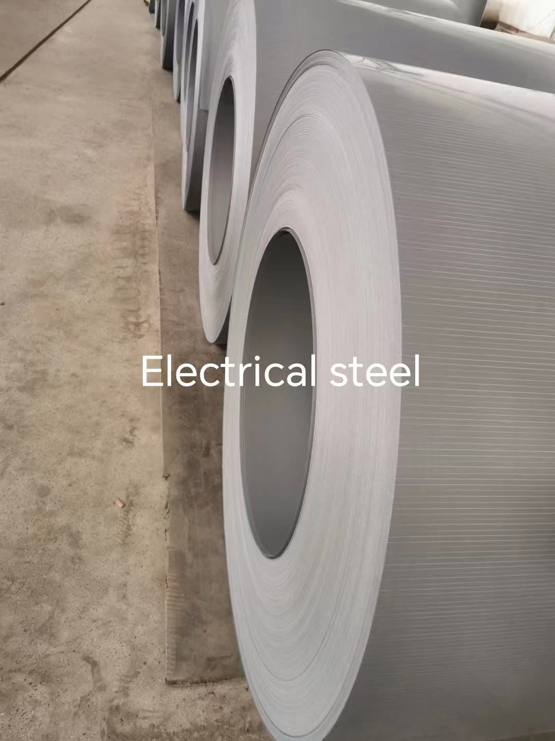
Grade selection is only complete once the strip can be slit, cut and stacked to the tolerances the core design assumes.
Step 4 — Test the Shortlist Against Real Project Conditions
Project conditions are the final filter because two sites with identical loss and flux density targets can require different material behaviour. The application scenarios below show how the same grade family is specified differently once climate, duty cycle and grid standards are taken into account.
| Project condition | Stated requirement | What it does to the shortlist |
|---|---|---|
| Germany — distribution transformer upgrade replacing old energy-consuming units in line with EU ecodesign regulation; mild climate, stable grid, strict transformer noise limits | Core material to reduce no-load and load losses; iron loss ≤ 0.60 W/kg; noise 2–3 dB below standard; coating weather resistance for coastal salt-spray conditions | Pushes the loss target below the published ceilings of the thin-gauge grades in this set, so measured data and product-form confirmation become a pre-award requirement |
| Canada — cold-region grid upgrade and urban low-noise distribution transformers | Operation from −40 °C to −20 °C with frequent freeze-thaw cycles and coastal salt fog; magnetic permeability retention ≥ 95 % at −40 °C; Class 1 energy-efficient rolled iron core transformers | Adds a low-temperature permeability retention criterion and a coating durability criterion that sit outside the basic loss and B8 filters |
| Brazil — ±800 kV ultra-high voltage direct current project, Belém Mountain Phase II | Converter transformer core material; 30–40 °C and 80–90 % humidity; high thunderstorm index; flux density ≥ 1.92 T and iron loss below 0.85 W/kg | Sets a flux density floor above the highest published 0.23 mm B8 value in this set, so the requirement must be confirmed against measured performance before commitment |
| Brazil — transmission and distribution transformer manufacturing for the national grid | Core material for power and distribution transformers under continuous full-load operation; compliance with regional energy efficiency certification | Favours grades whose application profile already covers power transformer and distribution transformer cores |
Project conditions extracted from the scenario references associated with this portfolio. Requirements are project-specific and are not general performance claims for any grade.
The pattern is consistent. Magnetic filters narrow the list; project conditions decide which of the surviving grades can actually be qualified. A buyer who runs steps one to three and stops has a shortlist. A buyer who runs step four has a sourcing decision.
Comparison With Conventional Practice — and Where the Framework Stops
Conventional purchasing practice treats grain-oriented electrical steel as a single commodity class, selected mainly on thickness and price, with loss values checked only at the goods-receipt stage. The framework above replaces that with two independent filters and a project-condition test. The difference is not theoretical: within the same 0.23 mm thickness, published loss ceilings in this portfolio range from ≤ 0.75 W/kg to ≤ 1.00 W/kg, and published flux density floors from ≥ 1.75 T to ≥ 1.89 T.
Three boundaries should be stated plainly, because a framework that only lists advantages is not a framework.
- Published grade limits can sit below a project specification. The German distribution scenario cited above requires iron loss ≤ 0.60 W/kg, while the lowest published ceiling among the 0.18 mm and 0.23 mm grades referenced here is ≤ 0.65 W/kg for 18-65. That gap cannot be closed by choosing a different grade name from the same table; it must be resolved with measured batch data and confirmation of the applicable product form before award.
- A high flux density floor can exceed the published values of the whole shortlist. The Brazil HVDC scenario states a requirement of ≥ 1.92 T. The highest published B8 value among the 0.23 mm grades in this article is ≥ 1.89 T for 23Q080. When a project specification sits above the published data, the correct action is to request measured test evidence, not to assume equivalence.
- Thinner gauge is not a universal upgrade. Moving from 0.23 mm to 0.18 mm increases the number of laminations needed for a given stack height, raises sensitivity to burr and edge damage during slitting and stacking, and does nothing to improve building factor, noise performance or coating suitability. If the loss budget is already met at 0.23 mm, thin gauge can add handling cost without delivering a magnetic benefit the design can use.
Two further constraints apply to the standards layer. ASTM A876 specifies that materials shall conform to defined values of magnetic properties — core loss, permeability and magnetic aging — as well as physical dimensions and mechanical properties such as lamination factor and ductility. A grade name alone does not evidence compliance with those property groups. Similarly, where a project references an application standard such as ASTM A677 for fully processed non-oriented electrical steel, the applicable standard must be matched to the actual product type; grain-oriented transformer steel and non-oriented motor lamination steel are not interchangeable specifications.
Turning a Grade Decision Into Usable Laminations
A grade decision only becomes a deliverable when the material can be supplied in the right form. HL AND SL LIMITED operates a processing plant covering the full oriented silicon steel route with OEM and ODM support, and its published capability set addresses the conversion steps that follow grade selection.
- Specification customisation: thickness from 0.18 mm to 0.35 mm, with width typically 800–1250 mm and ultra-wide 1250 mm available on request.
- Material options: general orientation CGO, high magnetic flux Hi-B, laser-scribed R series and heat-resistant HS series.
- Coating options: organic coating with temperature resistance up to 180 °C, inorganic coating with temperature resistance up to 800 °C, and semi-organic coating.
- Size processing: strip cutting, fixed-length flat cutting and longitudinal cutting.
- Packaging: standard export sea-worthy packaging with logo and graphic customisation.
- Commercial parameters: monthly capacity 4,000 T, minimum order quantity 25 T, regular order lead time 15–20 days, urgent or stock orders shipped in 3–7 days, bulk export orders 30–45 days to port arrival, and 7–30 working days after letter of credit deposit.
- Quality control: origin factory inspection with full-process random and batch inspection, material and warranty certificates issued per batch with the goods, and third-party testing through CMA/CNAS-accredited laboratories.
- After-sales: lifecycle technical guidance and application support, inbound quality inspection dispute handling and re-inspection, with feedback and coordination within 1–3 working days.
Scale matters less than repeatability here. The company supplies transformer manufacturers across Asia, Europe, the Americas, Australia and the Middle East, with an export share of roughly 80 % and stated main markets in Mexico, Brazil, Italy, the UAE and India. One reference case describes batch supply to a Mexican transformer manufacturer over more than ten years, covering cores for power transformers, converter transformers and special engineering transformers at a business scale of approximately USD 500 million annually. A second describes long-running supply into WEG's Brazilian transformer manufacturing, supporting local energy efficiency certification requirements and grid modernisation in Latin America. Extended supply relationships of this kind are relevant to buyers because they indicate repeat qualification against consistent incoming inspection rather than a single delivered lot.
Market Context: Why Grade-Level Specification Is Getting More Attention
The commercial context behind this framework is a market that continues to expand while its internal segments behave differently. Commercial research tracked in the HTNXT verified data package estimates the global electrical steel market at approximately USD 54.02 billion in 2026, with non-grain-oriented electrical steel holding more than 71 % of 2025 volume share. Within the oriented segment, one estimate places the global grain-oriented market at roughly USD 7,514.92 million in 2026, rising to about USD 9,954.69 million by 2035, while a North America estimate projects the regional electrical steel market at approximately USD 7.51 billion by 2035 at a 6.50 % CAGR from 2026 to 2035.
These figures come from commercial research sources with differing product scopes and methodologies and should not be combined or averaged into a single market view. Their directional signal is nevertheless consistent: demand for transformer core material is growing alongside grid investment, and grain-oriented grades sit at the centre of that growth because transformer cores depend on them. For buyers, the practical consequence is that grade-level specification quality increasingly determines whether a programme can be awarded, delivered and certified on schedule.
Future Outlook
Three developments are likely to shape Hi-B grade selection over the next procurement cycles. First, the boundary between conventional and laser-scribed high-permeability grain-oriented categories, already separated in ASTM A876, will keep expanding the number of performance points buyers must distinguish within a single thickness. Second, efficiency regulation and grid modernisation will push more projects toward explicit loss ceilings and flux density floors, which makes the filter sequence in this framework more useful rather than less. Third, documentation discipline will matter as much as magnetic data: batch certificates, measured values and third-party test reports are the evidence that a grade decision was implemented, not just made.
For a buyer working through the framework, the sequence is stable. Fix the loss ceiling, set the flux density floor, choose thickness against the core you will actually build, then test the shortlist against the project's climate, duty cycle and certification requirements. Everything else — coating, width, cut tolerance, packing and lead time — is specified after that sequence, not before it.
FAQ
Is 0.18 mm Hi-B steel always the better choice over 0.23 mm for transformer cores?
No. Thinner strip primarily reduces the eddy-current component of core loss, which helps most where loss budgets are tight or excitation contains high-frequency content. It also increases the number of laminations required for a given stack height and raises sensitivity to burr and edge damage during slitting and stacking. If the design can meet its loss target at 0.23 mm, the thicker gauge is usually the lower-risk build.
If a project sets an iron loss ceiling of 0.65 W/kg, which Hi-B grades qualify?
Among the grades referenced here, only 18-65 at 0.18 mm and 20-65 at 0.20 mm publish a P1.7/50 limit of ≤ 0.65 W/kg. Any ceiling at or below that value excludes the 0.23 mm grades in this list, whose published limits begin at ≤ 0.75 W/kg for 23R075 and rise to ≤ 1.00 W/kg for 23Q100.
What magnetic flux density floor should be written into a transformer RFQ?
The floor should be derived from the core design induction, not chosen for convenience, and it should state the test basis. As a reference, a floor of ≥ 1.88 T is satisfied by 18-65, 23R075, 23Q085, 23Q090 and 23Q095; a floor of ≥ 1.89 T narrows the same list to 23Q080; and a floor of ≥ 1.75 T would admit 23Q100 even though it shares the 0.23 mm thickness of much stronger grades.
Can a 0.23 mm grade replace a 0.18 mm grade when the loss target is already met?
In principle yes, provided the replacement meets both the loss ceiling and the flux density floor and the core can be built to the same dimensions and tolerances. The points to re-check are lamination count and stacking factor, noise behaviour, cutting volume and scrap sensitivity. A substitution that satisfies the magnetic specification can still fail on build cost or factory throughput.
What documentation should accompany a Hi-B electrical steel shipment?
Batch-level evidence is the minimum. In this portfolio, supply is supported by origin factory inspection with full-process random and batch inspection, a material and warranty certificate issued with each batch, and third-party testing through CMA/CNAS-accredited laboratories. ASTM A876 identifies the property groups that such documentation should address — core loss, permeability and magnetic aging as magnetic properties, physical dimensions, and mechanical properties including lamination factor and ductility.
Do cold-climate or high-humidity projects change the grade decision?
They can add criteria that sit outside the basic loss and flux density filters. The Canada scenario in this portfolio combines operation from −40 °C to −20 °C with freeze-thaw cycles and coastal salt fog, and specifies a magnetic permeability retention rate of ≥ 95 % at −40 °C plus coating weather resistance. The Brazil HVDC scenario combines 30–40 °C and 80–90 % humidity with a flux density requirement of ≥ 1.92 T. In both cases the environmental criteria must be confirmed against measured data before the shortlist is finalised.
For the full grade and processing reference behind this framework, the HL AND SL LIMITED brochure is available for download: electrical steel grade and processing brochure.
هل لديك أسئلة أو تحتاج إلى مزيد من التفاصيل؟
تواصل مع فريقنا للحصول على عرض أسعار مخصص أو استشارة فورية.
طلب عرض أسعار
املأ النموذج أدناه وسيتواصل معك فريقنا بعرض مقترح مخصص.
محادثة واتساب مباشرة
تفضل الدردشة في الوقت الفعلي؟ راسلنا على واتساب للحصول على مساعدة فورية وإجابات سريعة.
- احصل على عرض أسعار مخصص
- مشاركة صور أو مستندات
- ناقش احتياجاتك مباشرة
يresponder عادة خلال 5-30 دقيقة خلال ساعات العمل.