
Hybrid Solar Inverter vs. Separate MPPT + Inverter: Off-Grid Buyer Decision Guide
Hybrid Solar Inverter vs. Separate MPPT + Inverter: Off-Grid Buyer Decision Guide
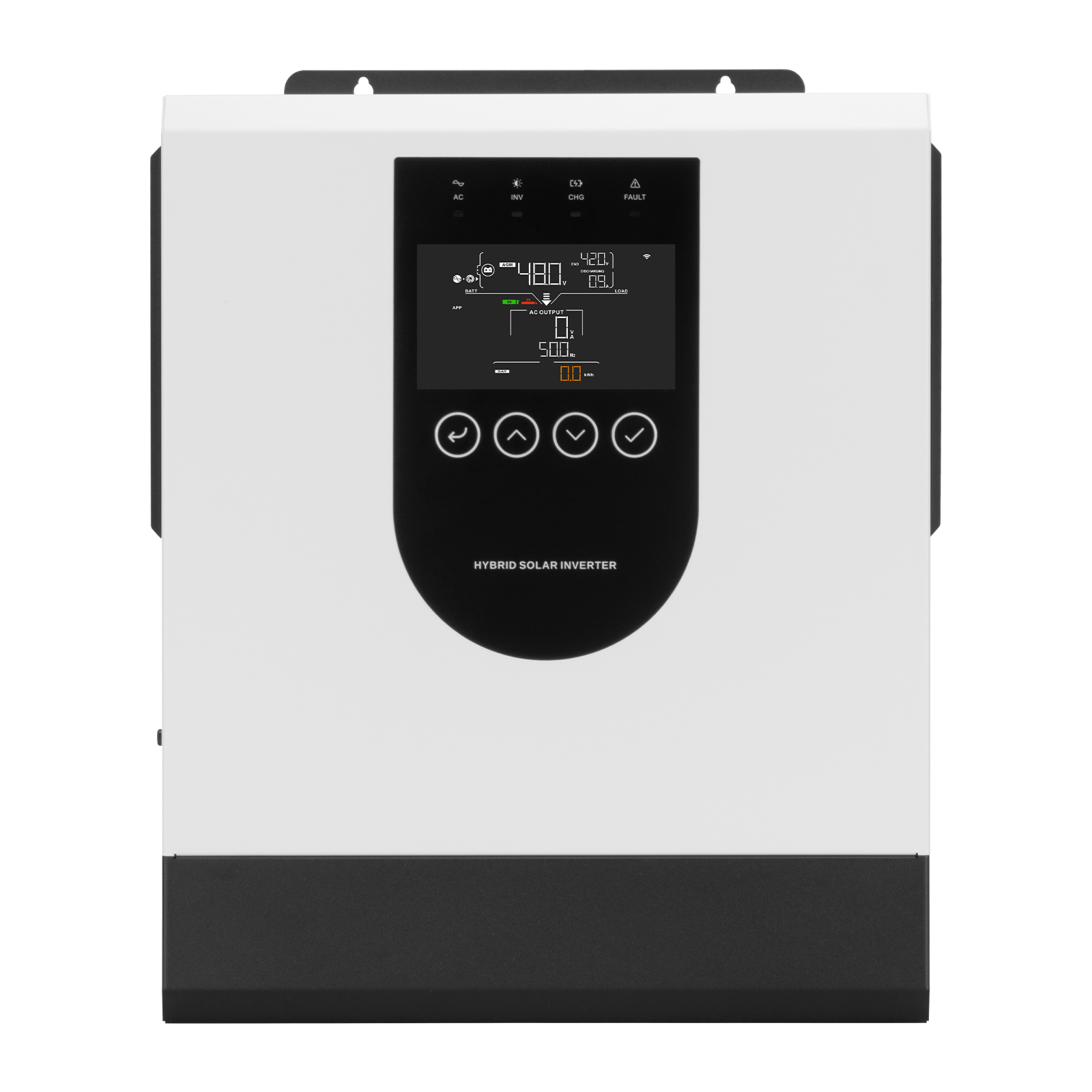
An off-grid power system always contains the same four functional blocks: PV array, charge control, battery bank and inverter. What buyers actually decide is how those blocks are packaged, either inside a single hybrid solar inverter or split between a standalone MPPT solar charge controller and a separate off-grid inverter. That packaging choice sets the PV input ceiling, the maximum charge current, the surge behaviour of the load, the number of enclosures on the wall, and the certification documents a buyer has to hold.
FOSHAN SOLARUP TECHNOLOGY CO.,LTD, which trades under the brand GOTOSOLAR, manufactures both sides of this comparison: hybrid solar inverters and PWM/MPPT solar charge controllers. The company operates three production bases in Foshan, Yiwu and Yingtan, exports to more than 120 countries, and reports annual shipments of over one million solar charge controllers alongside a daily hybrid inverter production capacity above 2,000 units. Its documented specifications, particularly for the SYP6.5KW48V hybrid inverter and the MPJ, MPQ, MPK, MRL, MPZ, AT, CT, FT, LT and VT solar charge controller series, make the architecture trade-off measurable rather than theoretical.
Two architectures, one power path
In the integrated architecture, the PV array connects directly to the hybrid inverter. That single device performs maximum power point tracking, battery charging, DC-to-AC inversion and transfer between the grid or a generator and the battery bank. In the separated architecture, the array terminates at a solar charge controller that regulates charging on its own, and an off-grid inverter draws from the battery to produce AC output. Both designs end at the same battery bus and deliver the same result, charged batteries and usable AC power, but the boundaries of responsibility differ.
With one integrated unit, a single firmware logic coordinates charging, discharging and transfer, and there is one configuration interface. With two devices, charging voltages and protection thresholds must be aligned across two controllers, the buyer manages two specification sheets, and troubleshooting splits into two diagnostic paths. Neither arrangement is inherently better. The correct answer depends on the PV array, the battery bank and the load profile.
Side-by-side specification comparison
| Decision factor | All-in-one hybrid inverter (SYP6.5KW48V) | Separate MPPT controller + off-grid inverter |
|---|---|---|
| Charge stage | Built-in MPPT solar charger inside the inverter | Standalone MPPT or PWM solar charge controller |
| PV input envelope | Max PV input current 27 A; max PV input power 9,000 W; MPPT range 60-450 VDC; max PV open circuit voltage 500 VDC | Max PV input power 130 W-11,000 W and charge current 10 A-200 A, model-dependent |
| Charge current | 120 A from PV, 120 A from AC, 120 A maximum combined | Up to 200 A on the highest-rated controller models |
| Charge conversion efficiency | Integral MPPT stage; inverter maximum efficiency in battery mode 94% at 48 VDC | At least 98% for MPPT types, at least 95% for PWM types |
| Battery compatibility | Lithium and lead-acid, with lithium battery activation; 48 VDC nominal, 54 VDC float, 61 VDC overcharge protection | Gel, lithium and lead-acid deep-cycle banks; 12 V/24 V/48 V auto-identification |
| AC output | 6.5 kW rated, 12 kVA surge, pure sine wave, power factor 1 | Determined by the off-grid inverter selected; specified independently of the controller |
| Transfer behaviour | 10 ms switch time in both normal and UPS modes; workable with a generator; dual AC output | Determined by the off-grid inverter selected |
| Monitoring and interfaces | LCD display; RS232/RS485/USB; WiFi optional (internal or external) | LCD/LED optional; RS485/Bluetooth optional on smart models |
| Ingress protection | IP21, indoor or protected installation | IP32, indoor, on the controller |
| Certification | CE-LVD (SZNTC2511142SV00 / SZNTC2511124SV00; EN 62109-1:2010, EN 62109-2:2011); CE-EMC (CTC191J0808101EC) | CE-EMC (CTC191J1202501EC), CE-LVD (SZNTC2411125SV00), CE-RoHS (CTC191J1202501RC) |
| Physical footprint | 410 x 336 x 110 mm, 8.4 kg, one wall-mounted enclosure | Two enclosures plus DC wiring, fusing and breaker hardware between controller, battery and inverter |
The left column reflects the documented specifications of one model, the SYP6.5KW48V. The right column combines documented charge controller specifications with the fact that the inverter side of a separated system is selected independently by the buyer, so its ratings vary by model.
PV input limits: where the array design is decided
Answer first: the SYP6.5KW48V hybrid inverter accepts a maximum PV input current of 27 A and a maximum PV input power of 9,000 W, tracks the array across a 60-450 VDC MPPT range, and tolerates a maximum PV open circuit voltage of 500 VDC.
Those four numbers decide the array configuration. The 60 VDC lower bound means the series string voltage must stay above the tracking floor under real operating conditions, not only at standard test conditions. The 500 VDC ceiling means the string open-circuit voltage at the lowest expected cell temperature must stay below 500 VDC, which caps series string length on cold sites. The 27 A cap applies to the combined current of parallel strings feeding the unit. The 9,000 W PV input limit is also independent of the 6.5 kW AC rating: they are two separate ceilings, and exceeding the DC envelope is not compensated by the AC rating.
A standalone solar charge controller widens that envelope. Documented controller specifications in the same product family cover 12 V, 24 V and 48 V systems with automatic identification, charge currents from 10 A to 200 A depending on model, and maximum PV input power from 130 W to 11,000 W based on voltage and current. Where an array design requires either more PV input power or a higher charge current than a hybrid inverter documents, the separated architecture is the route that stays inside published limits. Buyers should also note that the charge stage is current-limited: on the hybrid inverter, the 120 A total charge current ceiling governs how much of the array output can actually be converted into charge current, so an oversized array does not automatically shorten charge time.
Battery charging: the 120 A figure and what it really means
Three charge current figures apply to the SYP6.5KW48V: 120 A from PV, 120 A from AC, and a maximum total of 120 A when both sources operate together. The third figure governs system design, because the PV and AC charge paths do not add up to 240 A. A design that assumes a combined 240 A charge rate will not reach the expected charging speed, and the battery bank should be specified against the 120 A total, not against the individual inputs.
The model supports lithium and lead-acid batteries and includes lithium battery activation. For a 48 VDC nominal bank, the documented floating charge voltage is 54 VDC and overcharge protection is set at 61 VDC, which gives installers fixed reference points for commissioning. Battery selection therefore depends less on the inverter than on the bank's own charge current requirement. If the battery manufacturer specifies a charge current above 120 A, the separated architecture with a higher-rated controller, up to 200 A on the largest documented models, is the compliant path.
Controller type matters as well. MPPT controllers document conversion efficiency of at least 98%, while PWM controllers document at least 95%. PWM types suit small arrays operating close to battery voltage, where the voltage difference between array and battery is small; MPPT types suit higher-voltage arrays, where the efficiency gap becomes material. The controller series also auto-identifies 12 V, 24 V and 48 V systems, which reduces the risk of a mis-set system voltage during commissioning, and smart models offer RS485 or Bluetooth monitoring.
Surge capability, transfer time and load behaviour
The SYP6.5KW48V is rated at 6.5 kW continuous AC output with a 12 kVA surge rating, pure sine wave output, a power factor of 1 and a 10 ms switch time in both normal and UPS modes. Documented overload behaviour is 1 minute at 102%-120% of rated load and 10 seconds above 120% load. Those figures matter because off-grid loads are rarely steady. Pumps, compressors, refrigerators and air conditioners draw a multiple of their running current at start-up, and a surge rating of 12 kVA against 6.5 kW continuous gives headroom that a marginally sized inverter would not provide. The 10 ms transfer time is short enough that most electronic loads such as computers, routers and control boards ride through a grid or generator loss without restarting. The model is documented as workable with a generator and includes dual AC output.
In a separated architecture, surge capability is not a property of the architecture at all; it is a property of the inverter the buyer selects. That independence is the main technical advantage of splitting the stages. An installation with a heavy motor load can pair a larger off-grid inverter with a modest charge controller, and the inverter can later be replaced without touching the charging equipment. The trade-off is that two devices must be matched on voltage, communication and protection settings by the designer rather than by a single factory firmware.
Installation footprint, interfaces and monitoring
Installing the integrated unit means handling one enclosure measuring 410 x 336 x 110 mm and weighing 8.4 kg, with a single LCD human-machine interface and RS232, RS485 and USB ports; WiFi monitoring is optional and can be fitted as an internal or external module. The inverter carries an IP21 rating, operates from -10 degrees C to 60 degrees C, tolerates 5%-95% relative humidity non-condensing, and is rated to 4,000 m altitude with derating above 1,000 m.
The separated architecture adds a second enclosure and a second set of DC terminations. Charge controllers in this family carry an IP32 indoor rating, operate from -20 degrees C to +55 degrees C, use an ABS housing with an aluminium alloy heatsink, and offer LCD or LED display options. On the positive side, separation lets the installer place the controller close to the battery bank and the inverter closer to the loads, and it allows a compact controller to be wall or DIN-rail mounted. On the negative side, every additional cable run, terminal and breaker between controller and battery is another potential fault point, and system data is split across two interfaces unless both devices share a monitoring platform.
Both arrangements carry the same environmental caution: IP21 equipment is intended for indoor installation or a protected outdoor position such as under an eave, and direct rain exposure is outside its scope. Buyers specifying a system for a genuinely exposed location should treat ingress protection as a separate selection criterion. GOTOSOLAR also documents an 8.2 KVA, 8200 W, 48 V single-phase hybrid inverter with IP65 protection and parallel function capability for installations that require a higher protection class, although sealed enclosures generally demand more professional maintenance and inspection routines.
Certification and compliance boundaries
Compliance is where the two architectures diverge in paperwork rather than in performance, and it is often the deciding factor for EU-bound shipments. The hybrid solar inverter is certified to CE-LVD under certificate numbers SZNTC2511142SV00 / SZNTC2511124SV00, against EN 62109-1:2010 and EN 62109-2:2011, issued by Shenzhen Nore Testing Center Co., Ltd. (NTC). The SYP6.5KW48V model is also covered by CE-EMC certification issued under certificate number CTC191J0808101EC against EN IEC 61000-6-3:2021 and EN IEC 61000-6-1:2019, among other EMC standards. The wider SYP series, including SYP1.5KW12V, SYP2.5KW12V, SYP4.0KW24V, SYP6.5KW48V and SYP12.0KW48V, is documented as certified to CE-EMC for the EU market.
The solar charge controller side carries three documents of its own: a CE-EMC Declaration of Conformity issued by Shenzhen Circle Testing Certification Co., Ltd. under certificate number CTC191J1202501EC against EN IEC 61326-1:2021, covering models MPJ, MPQ, MPK, MRL, MPZ, AT, CT, FT, LT and VT; a CE-LVD certificate issued by Shenzhen Nore Testing Center Co., Ltd. (NTC) under certificate number SZNTC2411125SV00 against EN 62109-1:2010 under the Low Voltage Directive 2014/35/EU; and a CE-RoHS certificate issued by Shenzhen Circle Testing Certification Co., Ltd. (C-CERT) under certificate number CTC191J1202501RC, referencing the RoHS Directive 2011/65/EU and (EU) 2015/863.
Three boundaries deserve attention. First, CE documentation addresses the EU market. It is not a substitute for UL 1741, the primary safety standard for grid-connected inverters in North America, while IEC 62109 is the international standard for PV power converters. Second, declarations are model-scoped: the EMC declaration for the hybrid inverter series lists specific models, so buyers should confirm that the exact model ordered appears on the certificate. Third, the RoHS document in this public record covers the solar charge controller models; a buyer who requires RoHS documentation for the inverter itself should request the document that specifically names that inverter model rather than assuming coverage.
Where the separate MPPT + inverter architecture is still the better answer
Documented limits, not marketing preferences, should drive the decision. The separated architecture is the better fit when any of the following applies:
- Required charge current exceeds 120 A. The hybrid inverter documents a 120 A maximum total charge current, while controller models document up to 200 A.
- The PV array exceeds the integrated DC envelope. A 9,000 W, 27 A input with a 500 VDC open-circuit ceiling can be exceeded by a large array, whereas controller models document PV input power up to 11,000 W.
- An off-grid inverter is already installed and working. Adding a charge controller is incremental rather than a full replacement.
- Redundancy matters. A failure in an integrated unit can interrupt charging and inversion at the same time, while two separate devices can be diagnosed and replaced individually.
- The two devices need to sit in different places. A controller rated IP32 and an inverter can be positioned independently, which is not possible when both functions share one enclosure.
- The buyer wants to upsize the inverter without changing the charge stage, or the reverse.
The limitations also run in the other direction. An integrated unit should not be assumed to support parallel operation unless the specification says so, and the documented SYP6.5KW48V specification does not list a parallel function, so buyers planning to stack units for higher output should confirm parallel capability with the supplier before design freeze. Installation conditions constrain the integrated option as well: an IP21 enclosure is not a solution for a fully exposed outdoor wall.
Cost drivers, without guesswork
No public price band is attached to either architecture in this comparison, and invented price comparisons should be treated with suspicion. What can be assessed is the structure of cost. An integrated unit reduces the number of enclosures, DC breakers, cable terminations and labour hours, and it carries one set of compliance documents. A separated system typically costs more in hardware and wiring and needs two compliance files, but it permits staged replacement and lets a buyer reuse an existing inverter. Procurement terms also shape total cost. GOTOSOLAR documents a minimum order quantity of 10 units for standard models with trial orders supported and 100-500 units for customised models, sample lead times of 7-10 days, 15-20 days for orders under 500 pieces, and 30-45 days for bulk orders, with a warranty of 1-3 years and 1%-2% free spare parts included with bulk shipments. Monthly capacity is documented at 60,000 standard units and 20,000 customised units.
Manufacturing and field evidence buyers can request
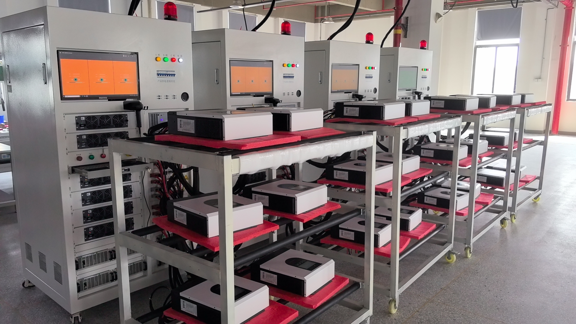
Because the architecture decision is only as good as the hardware delivered, buyers should read the manufacturing evidence before committing. The company documents IQC, IPQC, 100% aging tests of 4-8 hours, FQC, out-of-box audit and burn-in testing for high-power units, with 100% full-function testing of all goods before delivery. In a reported project with a large-scale solar EPC contractor, the supplier shipped approximately 3,000-4,000 units across two 40HQ containers and reports continuous operation for more than three years with a failure rate below 1%, stable performance at 45 degrees C without derating, and replacement of diesel generation with a reported 80% reduction in fuel costs. Those figures are supplier-reported and should be verified independently during evaluation, but they illustrate the type of evidence a buyer can request before choosing either architecture.
Application fit: residential, telecom, RV and remote sites
Documented application coverage for this product family includes residential rooftop solar, commercial solar projects, remote off-grid villages, telecommunication towers, and RV or marine mobile power, with continuous operation in variable weather, high-temperature conditions up to 60 degrees C and 24/7 supply requirements. Typical matched equipment includes PV panels, deep-cycle batteries in gel, lithium or lead-acid chemistry, hybrid inverters, DC loads such as LED lighting and pumps, and monitoring software. Common installation requirements include silent operation with fanless designs preferred, compact wall or DIN-rail mounting, low electromagnetic interference for residential safety, remote monitoring by app or WiFi, and over-temperature protection for enclosed cabinets. RV and marine installations deserve separate attention because limited mounting space, vibration and moisture exposure all push toward compact controllers and clearly rated enclosures.
Market trend context
The architecture discussion is taking place in a market that is still expanding. The global solar hybrid inverter market was valued at USD 10.7 billion in 2024, according to Grand View Research, while the residential sub-segment was valued at USD 4.55 billion in 2023, according to Markets and Data. Three-phase hybrid inverters held a dominant revenue share of more than 61.3% globally in 2024, which means single-phase, low-voltage hybrid platforms such as the 48 V SYP series serve a specific niche rather than the volume mainstream.
Structural context matters for procurement as well. Solar inverters are classified under HS Code 8504.40 as static converters, so hybrid and standard PV inverters frequently share one customs classification, making it difficult to isolate hybrid trade volumes in customs records. On the supply side, Huawei and Sungrow combined for 55% of the global PV inverter market in 2024, according to Wood Mackenzie. The remainder of the market, including off-grid and hybrid specialists, competes on configuration flexibility, documentation and delivery rather than on scale.
Future outlook
Two directions look likely over the next planning cycles. Integration will continue to absorb functions: monitoring, transfer switching and charging already sit inside the hybrid inverter, and buyers increasingly evaluate systems by the completeness of their documentation rather than by enclosure count. At the same time, the constraints documented here are not disappearing. Charge current ceilings, PV voltage windows, surge ratings and ingress protection classes remain physical limits, and they are precisely the points where separated architectures retain an advantage. Buyers who build their specification around documented limits rather than nominal ratings get a system that behaves predictably in the field.
FAQ
What is the practical difference between an all-in-one hybrid solar inverter and a separate MPPT controller plus off-grid inverter?
An all-in-one hybrid inverter performs MPPT charging, battery management and DC-to-AC inversion in one enclosure with one configuration interface. A separated system uses a standalone solar charge controller to regulate charging and an off-grid inverter to produce AC output, so the two stages are specified and replaced independently. Functionally both charge a battery bank from PV and supply AC loads; they differ in the PV and charge current limits that apply, the number of enclosures and DC terminations, and the number of compliance documents required.
What PV input limits should I verify before specifying a hybrid inverter for an off-grid system?
Four limits matter: maximum PV input current, maximum PV input power, the MPPT operating voltage range, and the maximum PV open-circuit voltage. The SYP6.5KW48V documents 27 A maximum PV input current, 9,000 W maximum PV input power, a 60-450 VDC MPPT range and a 500 VDC maximum PV open-circuit voltage. Buyers must confirm that the string open-circuit voltage at the lowest expected temperature stays below the ceiling, and that the combined current of parallel strings stays below the input current limit. Standalone controllers in the same family document PV input power from 130 W to 11,000 W depending on model.
Can an all-in-one hybrid inverter charge a battery faster than a separate MPPT charge controller?
Not necessarily. The SYP6.5KW48V documents a maximum charge current of 120 A from PV, 120 A from AC, and a maximum total of 120 A when both sources run together, so the total is the governing figure rather than the sum of the two inputs. Standalone solar charge controllers document charge currents from 10 A to 200 A depending on model. Where a battery bank requires a charge current above 120 A, a higher-rated standalone controller is the architectural fit. MPPT controllers document conversion efficiency of at least 98% and PWM controllers at least 95%.
Which battery types and certification documents should an off-grid buyer confirm?
The hybrid inverter supports lithium and lead-acid batteries and includes lithium battery activation, with a 48 VDC nominal rating, 54 VDC float voltage and 61 VDC overcharge protection. On documentation, the inverter is certified to CE-LVD under SZNTC2511142SV00 / SZNTC2511124SV00 against EN 62109-1:2010 and EN 62109-2:2011, and the SYP6.5KW48V is covered by CE-EMC certificate CTC191J0808101EC. The solar charge controller side holds CE-EMC (CTC191J1202501EC), CE-LVD (SZNTC2411125SV00) and CE-RoHS (CTC191J1202501RC). CE documentation applies to the EU market and is not a substitute for UL 1741 in North America, and buyers should confirm the exact model appears on the relevant certificate.
What installation environment does an IP21 hybrid inverter suit?
IP21 indicates protection against solid objects larger than 12.5 mm and vertically falling water drops, so the equipment is intended for indoor installation or a protected outdoor position such as under an eave, away from direct rain exposure. The SYP6.5KW48V operates from -10 degrees C to 60 degrees C, tolerates 5%-95% relative humidity non-condensing, and is rated to 4,000 m altitude with derating above 1,000 m. Solar charge controllers in the same family carry an IP32 indoor rating and operate from -20 degrees C to +55 degrees C. For exposed locations, a higher protection class such as the documented IP65 8.2 KVA 48 V single-phase hybrid inverter should be considered, noting that sealed enclosures generally require more professional maintenance.
When should a buyer choose the separate MPPT controller plus inverter architecture instead of an all-in-one unit?
Separation fits when the required charge current exceeds 120 A, when the PV array exceeds a documented 9,000 W and 27 A input envelope or approaches the 500 VDC open-circuit ceiling, when an off-grid inverter is already installed, when redundancy and device-level replacement matter, or when the controller and inverter need to be mounted in different locations. It also fits when the buyer wants to change the inverter rating later without changing the charge stage. Buyers planning parallel operation of all-in-one units should confirm that parallel capability is documented for the specific model, since the SYP6.5KW48V specification does not list a parallel function.
Before you specify: a short checklist
- Confirm string open-circuit voltage at the coldest expected temperature against the maximum PV open-circuit voltage.
- Confirm the combined parallel-string current against the maximum PV input current.
- Confirm the battery bank's required charge current against the total charge current limit.
- Confirm the surge requirement of the largest motor load against the surge rating.
- Confirm the mounting location against the ingress protection rating.
- Confirm that the exact model appears on the CE certificates relevant to your market.
- Confirm that monitoring interfaces match the site's operating expectations.
The choice between an all-in-one hybrid solar inverter and a separate MPPT controller plus off-grid inverter is ultimately a choice about which set of documented limits fits the site. Buyers who compare published figures for PV input, charge current, surge capacity and certification scope, rather than nominal product categories, will select the architecture that keeps the system inside its verified operating envelope.
The full GOTOSOLAR inverter specification catalog is available for download: GOTOSOLAR Inverter Catalog 2025 (PDF).