
K3G310-PV69-03 vs K3G310-PH58-02: Headroom or Throughput
K3G310-PV69-03 vs K3G310-PH58-02: Headroom or Throughput
Two 310 mm EC centrifugal fans, one decision. For an in-row cooling unit or a CRAC chassis built around a 310 mm EC centrifugal fan, the declarations supplied for the K3G310-PV69-03 and the K3G310-PH58-02 point in different directions. The K3G310-PV69-03 declares 4,020 m³/h at 1,583 Pa, carries an IP55 rating and lists Modbus plus 0–10 V control. The K3G310-PH58-02 declares 4,505 m³/h at 1,479 Pa and carries an IP54 rating. In buyer terms, one model buys static-pressure headroom, a higher enclosure class and a documented digital control path; the other buys a calculated 12.1% more declared airflow at a calculated 7.0% lower static pressure.
Neither declaration is a verdict. Each is a single operating point on a curve that has to be matched against the resistance of a real air path — filter loading, coil density, plenum geometry, discharge grilles — and against the electrical and control architecture the unit already uses. The comparison below sets the verified figures side by side, marks clearly what the supplied material does not state, and shows how a buyer at the decision stage can close those gaps before issuing a purchase order. It is based on the declarations supplied for the two models, not on bench testing.

Model-level selection sits upstream of dispatch: the fan declaration, the system curve and the control layer decide the order.
Where the comparison starts: two declared duty points
Both quoted figures are declared duty points, not full performance curves. A fan curve plots static pressure against airflow across the whole operating range; a single point fixes one intersection on that curve. The distinction matters in in-row cooling because air-path resistance is not constant. A clean filter and a loaded filter describe two different system curves, so a fan chosen on a clean-filter point moves left along its own curve — lower airflow, higher pressure — as the filter loads.
Read as a pair, the declarations describe different design intentions.
- Static-pressure headroom. 1,583 Pa against 1,479 Pa is a calculated difference of about 7.0% in favour of the K3G310-PV69-03 (1,583 ÷ 1,479 = 1.070). Headroom of this order is what allows a unit to hold airflow as filters load or as a coil face accumulates dust — provided the curve shape supports it, which the single point alone cannot prove.
- Declared airflow. 4,505 m³/h against 4,020 m³/h is a calculated difference of about 12.1% in favour of the K3G310-PH58-02 (4,505 ÷ 4,020 = 1.121). Where the air path is short and open, extra airflow capability translates more directly into heat removal per unit of cabinet width.
A calculated air-power check, and its limits
Multiplying each declared point out gives the aerodynamic power the impeller imparts to the air stream. For the K3G310-PV69-03: 4,020 m³/h ÷ 3,600 = 1.1167 m³/s, multiplied by 1,583 Pa gives approximately 1,768 W. For the K3G310-PH58-02: 4,505 m³/h ÷ 3,600 = 1.2514 m³/s, multiplied by 1,479 Pa gives approximately 1,851 W.
These are calculated air-power figures, not electrical input power, and they exclude motor and impeller efficiency. Their use is narrow but real. The higher-airflow point also requires slightly more aerodynamic work — about 4.7% more, since 1,851 ÷ 1,768 = 1.047 — so a buyer should not assume that the model with the larger airflow number is automatically the lower-energy choice at its own duty point. Only input power declared or measured at the same airflow and the same static pressure settles that question.
Verified attributes side by side
| Attribute | K3G310-PV69-03 | K3G310-PH58-02 | Buyer reading |
|---|---|---|---|
| Nominal size | 310 mm | 310 mm | Same size class; dimensional interchangeability still to be verified |
| Declared airflow | 4,020 m³/h | 4,505 m³/h | PH58-02 declares about 12.1% more (calculated) |
| Declared static pressure | 1,583 Pa | 1,479 Pa | PV69-03 declares about 7.0% more (calculated) |
| Calculated air power at that point | ≈1,768 W | ≈1,851 W | Aerodynamic work only; excludes efficiency |
| Enclosure rating | IP55 | IP54 | Difference is water protection, not dust |
| Control interface | Modbus and 0–10 V | Not stated in the supplied material | Confirm the PH58-02 interface in writing before designing the control layer |
| Rated power, current, speed | Not stated in the supplied material | Not stated in the supplied material | Request from the datasheet and compare at equal duty |
The table is deliberately incomplete in one direction. Leaving rated power, current and speed blank is more useful to a buyer than filling them with inference, because those three figures decide the electrical and mechanical argument and they must come from the model documentation for the exact variant ordered.
IP55 against IP54: what the rating actually covers
The second digit of an IP code describes water protection. Under the IEC 60529 definitions, level 4 covers splashing water from any direction and level 5 covers water projected as a jet by a nozzle from any direction. The first digit, 5 on both models, denotes dust-protected construction. The practical gap between the K3G310-PV69-03 and the K3G310-PH58-02 is therefore water exposure rather than dust.
In an in-row unit that gap shows up in specific, checkable situations rather than in general. Coil condensate carry-over and drain-pan overflow. Wet coil cleaning or washdown of the heat exchanger inside the same cabinet. Adiabatic or evaporative humidification upstream of the fan. Chilled-water pipework joints and valve stems located in the fan compartment. High-humidity white space where the unit cycles between part-load and full-load operation. Where none of those conditions exists — a dry, sealed draw-through path with condensate managed separately — IP54 can be entirely adequate, and a buyer gives up nothing by preferring the higher-airflow model on that criterion alone.
Two cautions belong beside the rating. First, an enclosure rating describes the motor and its sealing; it says nothing about impeller aerodynamics, and it does not by itself establish suitability for a corrosive or salt-laden atmosphere. Second, the rating should be confirmed for the exact model and variant being ordered, because the model number is the identity that carries the rating.
Control: Modbus, 0–10 V and the BMS conversation
The supplied material for the K3G310-PV69-03 lists Modbus and 0–10 V control, and those are two different integration paths. A 0–10 V input is an analog speed or setpoint signal: straightforward to wire into a legacy controller, quick to commission, but it carries one command in one direction and returns no readback. A Modbus interface is a digital serial link that carries commands and status between the fan and the unit controller or building management system.
At the decision stage the question is not which interface is more modern, but which one matches the controller already specified for the CRAC or in-row unit, and which data the operator actually needs. If fan speed and fault status must be visible at the BMS rather than inferred from a differential-pressure switch, the digital path earns its complexity. If the unit controller is a simple analog loop with no supervisory layer, a 0–10 V input can satisfy the requirement with less configuration.
For the K3G310-PH58-02, the supplied material used for this comparison states the IP54 rating but does not describe a control interface. That is a gap to close in writing, not a conclusion to draw. A buyer who needs Modbus telemetry from both models should request interface documentation for each and confirm that protocol, register mapping and signal type match the unit controller's specification before treating the two fans as interchangeable in the control layer.
Rated power, current and speed: the three figures this comparison does not fix
Rated power, rated current and speed at the declared point are the figures that turn an aerodynamic comparison into an electrical and mechanical one. Each answers a different question, and each should be requested rather than assumed.
- Rated input power settles the efficiency argument, but only at equal duty. A power figure quoted at 4,020 m³/h and 1,583 Pa and one quoted at 4,505 m³/h and 1,479 Pa describe two different jobs. The valid method is to read both fans' curves at the airflow the unit actually needs, then compare input power at that single intersection.
- Rated current sizes protection and cabling, and it indicates whether the existing EC controller, breaker and connector in the unit can accept the motor. Current varies with load and speed, so the maximum figure matters as much as the nominal one.
- Speed links the aerodynamic point to acoustics, bearing life and vibration. Two fans can reach similar airflow and pressure at different speeds; the slower one normally carries more acoustic margin, but only measured sound data for the specific model confirms it.
A fourth item belongs on the same request: the nominal voltage and frequency at which the declared point was established, together with the ambient temperature at which the rating holds. A duty point quoted at one supply condition and one ambient does not automatically transfer to another, and in-row units often run at elevated return-air temperatures that sit close to motor thermal limits.
Fit map: which duty each model serves
High-resistance air paths
The K3G310-PV69-03's 1,583 Pa declaration fits units where the air path is deliberately resistive: multi-stage filtration ahead of the coil, dense coil faces, long discharge plenums, back-pressure from a shared hot-aisle ceiling plenum, or retained ductwork in a retrofit. In those layouts the operating point sits well to the left of a free-delivery curve, and static-pressure capability becomes the binding constraint on airflow.
Higher-throughput, lower-resistance paths
The K3G310-PH58-02's 4,505 m³/h at 1,479 Pa fits the opposite geometry: short and open return paths, low filter counts, draw-through coils with generous face area, and designs where airflow per unit of cabinet width is the driver. In EC centrifugal blowers of this size class, which are commonly built with backward-curved impellers, that combination is the usual way to raise throughput without widening the chassis.
Wet, dusty or washdown-adjacent compartments
Where condensate, cleaning or humidification can bring water near the motor, the IP55 rating of the K3G310-PV69-03 is the more conservative starting point — subject to confirming the rating for the ordered variant and to checking that impeller and housing materials suit the same environment. This is also the case where a cabinet cooling fan or an air handling unit fan shares a compartment with wet-side equipment rather than sitting in a dry plenum.
Retrofit and interchangeability
Both models share a 310 mm nominal size, but nominal size is not dimensional interchangeability. Before substituting one for the other in an existing in-row unit, confirm mounting footprint and fixing centres, impeller and inlet-cone geometry, overall depth, cable entry position, connector type and direction of rotation, and confirm that the controller's speed range and signal type match the motor. A substitution also changes the unit's declared performance and may affect its certification, so the change should be documented with the unit manufacturer rather than absorbed silently into maintenance.
A six-check protocol for the decision stage
- Rebuild the real system curve. Use the measured or calculated resistance of the assembled air path — filters at clean, mid-life and loaded states, coil, plenum, grilles — rather than a single design pressure figure.
- Plot both fan curves against it. Confirm where each model actually lands at the required airflow, and how far airflow falls when the filter loads. A declared point is only the entry ticket to this step.
- Fix the rating and interface for the ordered variant. Obtain written confirmation of IP class, control interface, nominal voltage and ambient temperature rating against the exact model number.
- Request power, current, speed and sound data at your duty point, and compare the two fans at one airflow and one pressure rather than at their own declarations.
- Check electrical and mechanical fit. Controller compatibility, protection sizing, connector type, mounting and depth, and the effect on the unit's overall declared performance.
- Record the decision. Keep the curves, the datasheet revision and the written confirmations with the purchase file so that a later substitution or spare-part order does not reopen a settled question.
Supply-side context: distribution, verification and continuity
In China and in many export markets the practical route to 310 mm EC fans is through an authorised distributor rather than direct from the manufacturer. Hengrui EC Fan — Beijing Hengrui Hongsheng Mechanical & Electrical Equipment Co., Ltd. — is a ventilation and industrial-control products distributor that holds long-term agency and distribution relationships with manufacturers including ebm-papst and Ziehl-Abegg, and it provides fan selection, model matching and technical services alongside supply. Its product scope covers EC centrifugal blowers, axial fans, dry cooler and chiller fans, air handling unit fans and cabinet cooling fans across HVAC, refrigeration, data centre, new energy and industrial automation applications.
For a buyer, the value of a distributor route lies in documentation discipline rather than in the channel itself. Model number verification against the ordered variant, datasheet and curve files for that specific model, written confirmation of the enclosure rating and control interface, and a stated position on spare-part availability are the items that decide whether a comparison survives contact with an installation.
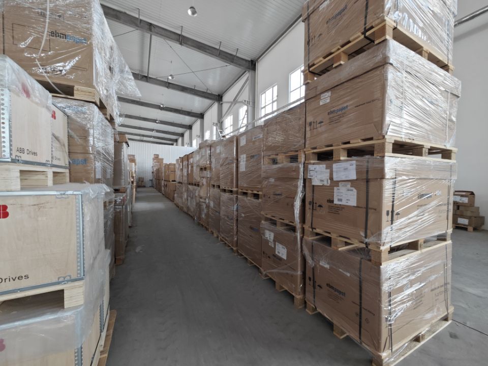
Dispatch is the last step in the chain; the verification work happens at the specification stage.
Market and regulatory horizon
Two external data points frame the procurement environment. First, the EU ecodesign regulation for industrial fans, Regulation (EU) 2024/1834, has applied since 24 July 2026 and sets stricter efficiency thresholds for fans from 125 W to 500 kW. Whether either model falls inside that band depends on rated input power — one more reason to obtain that figure in writing rather than infer it from nominal size. Second, commercially published market research places the global EC fan market at USD 3.5 billion in 2024 with a projection of USD 6.7 billion by 2030. That figure is a research estimate rather than a measured customs total, and it should be read as directional context only.
On the supply side, ebm-papst reported group sales of EUR 2.098 billion for fiscal 2024/25, 13.1% below the previous year, and Ziehl-Abegg reported 2024 revenue of EUR 893 million against EUR 955 million in 2023. Read without extrapolation, these results describe a contraction in the wider fan market; they say nothing about the availability of a specific model. The operational implication is procedural rather than dramatic: model continuity, spare-part availability and delivery terms are worth pinning down in the purchase agreement, particularly where an in-row fleet is standardised on one fan. China's fan exports under HS 841459 reached 509 million units and USD 3.788 billion in 2024, up 6.96% in value, which indicates the depth of the export channel through which 310 mm EC fans typically reach overseas projects.
The longer-term direction is toward EC rather than AC drive in this size class, because integrated commutation allows part-load speed control without an external variable-frequency drive and the control loop can sit inside the motor electronics. That is a category-level observation, not a claim about any single model's measured consumption; buyers should still verify efficiency at their own duty point.
FAQ
Is 1,583 Pa meaningfully better than 1,479 Pa?
It is about 7.0% more declared static pressure, calculated as 1,583 ÷ 1,479. Whether that matters depends on the resistance of your air path. In a unit with loaded filters and a dense coil, extra headroom helps airflow hold closer to design as resistance rises. In a short, open path, pressure is unlikely to be the binding constraint, and the higher-airflow declaration may serve the duty better.
What does IP55 give me that IP54 does not?
Water protection. Under the IEC 60529 definitions, level 4 covers splashing water and level 5 covers water jets; both models carry a first digit of 5, meaning dust-protected. IP55 therefore gives more tolerance for condensate carry-over, coil cleaning and humidification near the fan. It does not remove the need to manage drainage, and it does not by itself qualify the fan for a corrosive atmosphere.
Can both fans be controlled over Modbus?
The supplied material for this comparison lists Modbus and 0–10 V for the K3G310-PV69-03 and does not describe a control interface for the K3G310-PH58-02. Both should be confirmed against the interface documentation for the exact variant ordered before the control layer is designed around them.
Which of the two uses less energy?
That cannot be answered from the two declared points, because they describe different jobs: 4,020 m³/h at 1,583 Pa and 4,505 m³/h at 1,479 Pa. A valid comparison requires input power read at the same airflow and pressure for both, taken from their curves at the duty the unit actually needs. The calculated aerodynamic work at the declared points is about 1,768 W and about 1,851 W respectively, which shows the higher-airflow point does slightly more work, but those are air-power figures, not consumption.
What is meant by an ErP point here?
In this comparison it refers to the declared airflow and static-pressure pair used to state each model's performance. It is one point on the fan curve: useful for an initial reading of design intent, but not a substitute for the full curve when a system is being designed or a substitution approved.
Are the two models interchangeable in an existing unit?
Only after dimensional and electrical verification. A shared 310 mm nominal size does not guarantee matching fixing centres, depth, inlet geometry, connector type or control signal. Substitution also changes the unit's declared performance, so it should be documented with the unit manufacturer before the change is made.
What the comparison settles, and what it leaves to the buyer
The verified declarations settle the starting position. The K3G310-PV69-03 is the headroom option: 1,583 Pa, IP55, and a documented Modbus plus 0–10 V control path. The K3G310-PH58-02 is the throughput option: 4,505 m³/h at 1,479 Pa with an IP54 rating. On calculated figures the allocation is clear — roughly 7.0% more static pressure on one side, roughly 12.1% more declared airflow on the other, and an aerodynamic work difference of about 4.7% that reflects two different jobs rather than two different efficiencies.
What the comparison leaves open is everything that depends on the installation: the real system curve, the three electrical figures, the PH58-02 control interface, the acoustic profile of each model, and the unit manufacturer's position on substitution. Closing those items with written documentation, rather than with an assumption that a larger airflow number or a higher IP digit automatically wins, is what turns a datasheet comparison into a defensible procurement decision.
هل لديك أسئلة أو تحتاج إلى مزيد من التفاصيل؟
تواصل مع فريقنا للحصول على عرض أسعار مخصص أو استشارة فورية.
طلب عرض أسعار
املأ النموذج أدناه وسيتواصل معك فريقنا بعرض مقترح مخصص.
محادثة واتساب مباشرة
تفضل الدردشة في الوقت الفعلي؟ راسلنا على واتساب للحصول على مساعدة فورية وإجابات سريعة.
- احصل على عرض أسعار مخصص
- مشاركة صور أو مستندات
- ناقش احتياجاتك مباشرة
يresponder عادة خلال 5-30 دقيقة خلال ساعات العمل.