
MCPCB Scenario Fit: Road, Motor and UV Lighting Boards
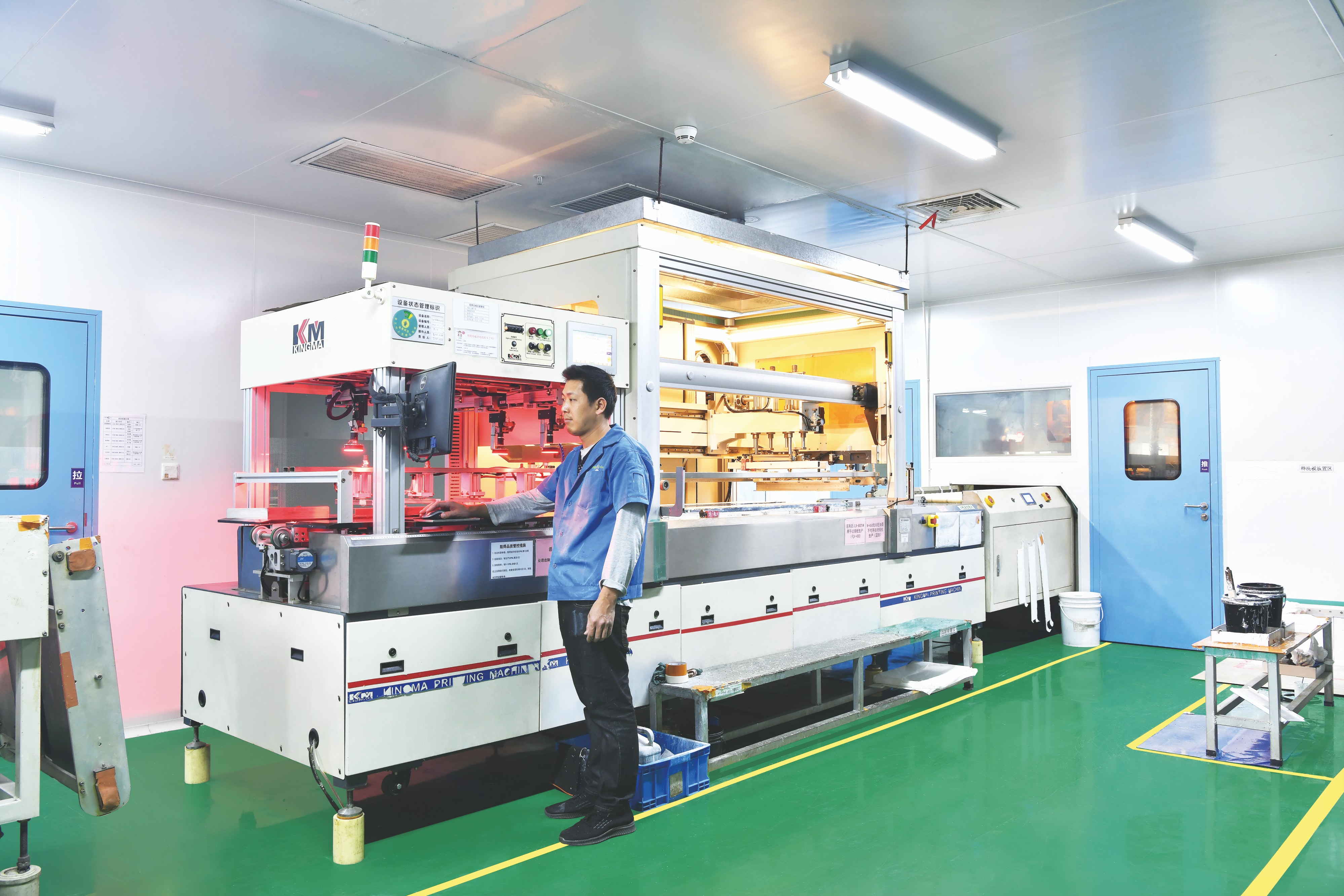
Metal core PCB production at WODE Circuit Technology (Zhuhai) Co., Ltd. — the same lines run road, motor, high-voltage and ceramic board families to different published specifications.
A metal core PCB rarely fails because the metal core was the wrong idea. It fails because one specific construction — alloy grade, copper weight, dielectric, and surface finish — was validated in one lighting application and then carried unchanged into another. Road lighting, motor lighting, high-voltage driver boards, and UV phototherapy devices all sit on the same broad family of metal core boards, yet they stress that family in different ways.
The practical answer is scenario matching. Base material, copper foil thickness, overall thickness, solder mask and surface finish are selected together against the thermal load, mechanical environment, electrical stress and optical requirements of the specific fixture. This article maps four primary lighting scenarios and three secondary board types to configurations published by WODE Circuit Technology (Zhuhai) Co., Ltd., a PCB and FPC manufacturer founded in 2003 and based in Zhuhai, China, and sets out the certification evidence and the boundaries a buyer should confirm before committing to production.
Why Scenario Fit, Not Material Choice, Decides MCPCB Performance
A metal core PCB is defined by four decisions that are usually compressed into one line on a quotation: the metal base alloy, the copper foil weight, the dielectric layer separating copper from the metal base, and the surface finish applied to the pads. Two boards can both be described as “aluminium, 1.6 mm, single sided” and still behave differently in a fixture, because the alloy grade, copper weight and dielectric are doing most of the work.
Lighting scenarios separate those variables quickly. Road lighting runs high-output emitter arrays over long duty cycles in outdoor temperature swings and moisture. Motor lighting adds vibration and mechanical loading to the same thermal problem. High-voltage lighting boards raise the electrical stress carried by the dielectric and demand a consistent, coplanar pad surface for downstream assembly. UV phototherapy equipment needs a substrate whose insulation and thermal behaviour stay stable under continuous operation.
That is why the evaluation stage of a lighting program should lock specifications by scenario rather than by board category. An MCPCB that is correctly specified for a road luminaire is not automatically the right board for a motorcycle headlamp, and neither is automatically the right board for a high-voltage driver module.
Matching MCPCB Construction to Four Lighting Scenarios
The table below compares the published specifications of the four primary boards used across these scenarios. Every value is taken from WODE’s product data.
| Lighting scenario | Board | Base material | Copper foil | Overall thickness | Solder mask | Surface finish |
|---|---|---|---|---|---|---|
| Road lighting | MCPCB for Road lighting | Al1060 | 1 oz | 1.6 mm ±10% | White | HASL-LF |
| Motor (motorcycle) lighting | MCPCB for Motor lighting | Al5052 | 1 oz | 1.6 mm ±10% | Matt Black | HASL |
| High-voltage OEM lighting | High Voltage MCPCB | Al1 | 1 oz | 1.6 mm ±10% | White | OSP |
| UV phototherapy | Ceramic based PCB | Ceramic | — | — | — | — |
Road lighting: Al1060 with a lead-free finish
WODE’s MCPCB for Road lighting is published as a single-sided board built on Al1060 aluminium with 1 oz copper foil, an overall thickness of 1.6 mm ±10%, white solder mask, black silkscreen, HASL-LF surface finish, and a panel size of 208.00 mm × 225.00 mm in a 2-up layout. The board is listed for the lighting industry.
Three of those choices carry most of the risk. Al1060 is a high-purity aluminium grade generally associated with thermal and electrical conduction rather than mechanical strength, which suits large emitter arrays where heat must spread quickly across the base. The 1.6 mm overall thickness gives the panel the stiffness that long road-lighting modules require during handling and assembly. HASL-LF is a lead-free hot-air solder levelling finish, which aligns with markets where lead-free assembly and RoHS-oriented documentation are standard. The white solder mask is a common choice in lighting modules, where light absorption around the emitter area is a design concern.
Motor lighting: Al5052 and a matt black mask
The MCPCB for Motor lighting is published on Al5052 aluminium, single sided, 1 oz copper, 1.6 mm ±10%, with a Matt Black solder mask, white silkscreen, HASL surface finish, and a 243.00 mm × 243.00 mm panel in a 1-up layout. It is also listed for the lighting industry.
The alloy change is the decision that matters. Al1060 and Al5052 are not interchangeable grades: Al5052 is an aluminium-magnesium alloy associated with higher mechanical strength, while Al1060 is associated with higher thermal and electrical conduction. Selecting between them is a trade-off between mechanical robustness and thermal spreading, not a simple upgrade path. For boards that live inside a motorcycle lamp housing, the mechanical side of that trade-off usually carries more weight. Matt black solder mask is a finish frequently specified where the board sits inside an optical chamber or a visible housing and reflection must be controlled, and the published finish here is HASL rather than HASL-LF — a difference worth confirming if the destination market requires lead-free processing.
High-voltage OEM lighting: Al1 with an OSP finish
The High Voltage MCPCB is published on an Al1 aluminium base, single sided, 1 oz copper, 1.6 mm ±10%, white solder mask, black silkscreen, OSP surface finish, and a 243.00 mm × 243.00 mm panel in a 1-up layout. Its listed industry is lighting.
OSP — an organic solderability preservative — keeps the pad surface flat and coplanar instead of adding a metallic layer, which supports consistent solder joints in fine-pitch surface-mount assembly and keeps the copper surface protected before reflow. On a high-voltage lighting board, the electrical stress is carried largely by the dielectric between the copper and the aluminium base, so dielectric thickness and breakdown performance should be confirmed against the actual circuit design rather than inferred from the metal base grade alone.
UV phototherapy: a ceramic substrate rather than a metal core
WODE’s Ceramic based PCB is published with a Ceramic material and a stated application of ultraviolet phototherapy. Ceramic substrates are used where the dielectric must combine electrical insulation with thermal stability under sustained operation, which is the condition UV phototherapy equipment creates. The trade-off is that ceramic is generally a higher-cost material path than aluminium, so the selection should be justified by the application rather than adopted as a default.
Secondary Board Types That Determine Whether a Program Fits
Three further constructions appear in the same published portfolio and often decide whether a scenario is feasible at all, because they exist precisely where a standard single-sided metal core board runs out of room.
| Board | Base material | Copper foil | Overall thickness | Panel | Solder mask / Silkscreen | Surface finish |
|---|---|---|---|---|---|---|
| Thermoelectric Separated Cu based PCB | Cu based | 35 µm | 1.6 mm ±0.16 | 133.80 mm × 120.00 mm, 4-up | White / Black | OSP |
| Double sided MPCB | Al5 | 70/70 µm | 1.6 mm ±0.16 | 217.54 mm × 197.80 mm, 56-up | White/White, Black/Black | HASL-LF |
| PCB for Small Appliance Lighting Motherboard | FR-4 | 1/1 oz | 1.0 mm ±0.1 | 340.05 mm × 150.00 mm, 30-up | Green / White | HASL-LF |
Thermoelectric Separated Cu based PCB. This board uses a copper base with 35 µm copper foil, a 1.6 mm ±0.16 overall thickness, white solder mask, black silkscreen, OSP finish, and a 133.80 mm × 120.00 mm panel in a 4-up layout, listed for lighting. The construction is named for the separation of thermal and electrical functions, which matters in dense emitter areas where heat must be extracted without routing the electrical path through the same layer as the thermal path.
Double sided MPCB. Built on an Al5 base with 70/70 µm copper, 1.6 mm ±0.16 overall thickness, white solder mask and black silkscreen on both sides, HASL-LF finish, and a 217.54 mm × 197.80 mm panel in a 56-up layout, it is listed for home applications. It is the answer when a single-sided metal core cannot carry the routing: the metal base is retained for thermal spreading while a second conductive layer absorbs the circuit complexity.
PCB for Small Appliance Lighting Motherboard. This board is FR-4, two-sided, 1/1 oz copper, 1.0 mm ±0.1 overall thickness, green solder mask, white silkscreen, HASL-LF finish, on a 340.05 mm × 150.00 mm panel in a 30-up layout. It is used in general lighting projects including bulb lamps, downlights and spotlights, under indoor operating conditions of 0 °C to +40 °C and humidity of 30% to 80%. Not every lighting board needs a metal core; where the thermal load is modest and routing density matters more, FR-4 remains the more economical route.
How WODE Produces Scenario-Matched Boards

Panel processing at WODE Circuit, Zhuhai — scenario matching ends in a production instruction, not a catalogue description.
WODE Circuit Technology (Zhuhai) Co., Ltd. was founded in 2003 and operates a 150,000 m² facility with more than 500 employees and an annual output of 6,000,000 sqm. Its main product lines cover rigid MCPCB, FPCB, infinity length FPCB, FR-4/CEM1/CEM3 PCBs and CCL, and PCB inks. Roughly 50% of output is exported, with main markets including Brazil, Turkey, India, Vietnam and Russia, and the company states it has supplied more than 1,000 customers in more than 30 countries.
For scenario matching, the operationally relevant facts are these:
- OEM / ODM production with defined customization scope. Customization covers laminate, PCB thickness, surface treatment, solder mask colour and logo printing — the exact parameters that differ between a road lighting board and a motor lighting board.
- Monthly capacity of 600k sqm and a stated lead time of 7–15 days, which matters when a scenario-matched board must be re-qualified mid-program.
- 100% testing of all products as the stated quality control approach, rather than sampling.
- An R&D team of 15 and more than 40 patented technologies, supported by in-house CCL production capacity.
Minimum order quantity is quoted by order type. Capability data lists 80 sqm; case records reference 100 sqm for mass orders with no limit on sample quantity; a purchasing record describes MOQ as ranging from 3 panels to 100 sqm depending on whether the order is a sample or a mass order. Buyers working from prototype to production should confirm the applicable MOQ at quotation stage rather than carry an assumption forward.
Certification Evidence Behind These Scenarios
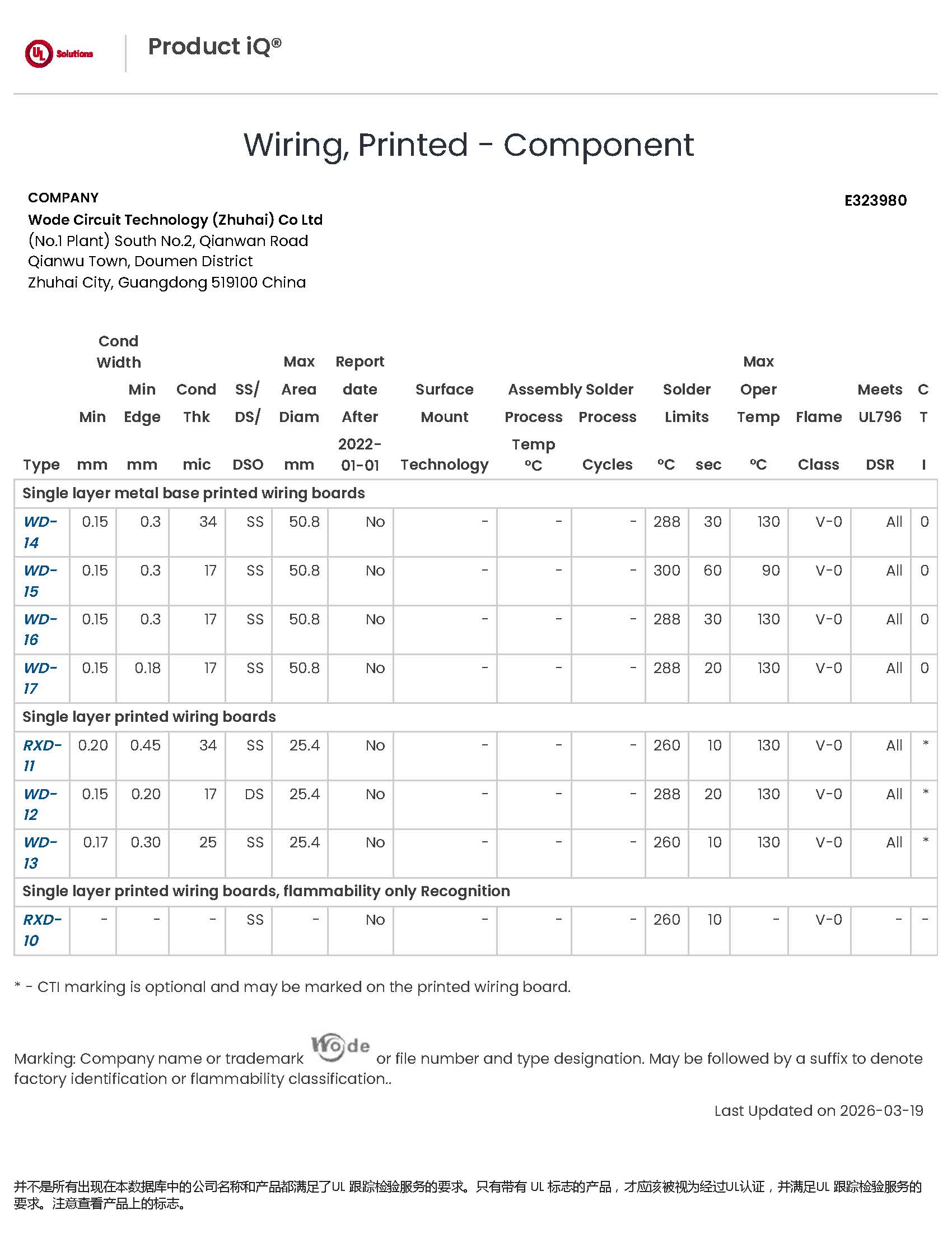
UL recognition E323980 covers single layer metal base printed wiring boards, the construction family used for road and motor lighting MCPCBs.
| Certification | Number | Issued by | Relevance to scenario fit |
|---|---|---|---|
| UL recognition, rigid PCB | E323980 | UL Solution | Single layer metal base printed wiring boards (models WD-14 to WD-17) and single layer rigid boards, to UL 796 |
| UL recognition, flexible PCB | E498836 | UL Solution | Single layer flexible printed circuits (WD-F1, WD-F2 / ASP1), to UL 796F and IPC-TM-650 2.6.27 |
| IATF16949 | 0584371 | NQA Certification Limited | Automotive printed circuit board manufacturing functions; issued 27 September 2025, valid to 26 September 2028 |
| ISO 9001:2015 | 51325Q4258ROM | Shenzhen Meiao Testing and Certification Co., Ltd | Production of circuit boards; issued 13 October 2025, valid to 12 October 2028 |
| ISO 14001:2015 | 51325E2142ROM | Shenzhen Meiao Testing and Certification Co., Ltd | Environmental management for circuit board production; valid to 12 October 2028 |
| CQC product certification | CQC22001367683 | China Quality Certification Centre | CEM-1 and FR-4 substrates, 0.2–3.2 mm, V-0 flammability, to GB 4943.1-2022; valid to 16 November 2027 |
| REACH test report | DGC251204025BD03 | NSTL | Double-sided aluminium-based board tested against EU REACH (EC) No 1907/2006 and the ECHA SVHC Candidate List; issued 10 December 2025 |
The company states that its products comply with UL, RoHS and REACH requirements, and that its management systems are certified to ISO 9001, ISO 14001 and IATF 16949. For a scenario-matching exercise, the important point is scope: the UL recognition covering single layer metal base printed wiring boards is directly relevant to road and motor lighting MCPCBs, while the REACH report applies to a double-sided aluminium-based board rather than to every board in the portfolio. Buyers should map the certificate scope to the specific board being ordered.
Application Evidence From Qualified Lighting Programs
Specification tables describe intent; installed programs describe behaviour. One published case is a lighting OEM project in Germany that ran for five years and used 5,000 sqm of PCB material as a main component of the project. The stated result is stable operation, with the highlights described as high thermal conductivity, reliable performance in the harsh European climate, and compliance with German safety standards. The duration and the climate requirement are the informative parts: a five-year outdoor-linked deployment tests the thermal path and the coating system together, not the metal base in isolation.
The same portfolio has been used by electronics manufacturers, lighting companies, OEM/ODM vendors and trading companies, and has been qualified by global brands including Signify, Osram, Opple, NVC, Honeywell, Randong, Dixon, Ozdisan, IKIO and Motheson. Typical applications listed for these boards include LED strips and fixtures, display module interconnects, and consumer electronics connectors. For high-volume lighting programs, the FR-4 lighting motherboard family covers bulb lamps, downlights and spotlights. Where outdoor protection is required, the stated special requirements for lighting applications are IP65/IP67 protection and a salt spray test of at least 1000 hours — a specification level that aluminium-based boards with appropriate coating systems are positioned to meet.
Where MCPCB Fit Ends: Limits, Boundaries and Alternatives
Scenario matching is only useful if the boundaries are stated as clearly as the capabilities. Five limits are worth checking before a specification is frozen.
- Metal core constructions are predominantly single sided. Every MCPCB in this portfolio — road, motor and high-voltage — is published as single sided. When a design needs two routing layers, the metal core approach requires a double-sided metal core board such as the published Double sided MPCB on Al5, or it moves to FR-4. Adding thermal performance and adding routing layers are different problems solved by different constructions.
- Alloy selection is a trade-off, not a hierarchy. Al5052 brings mechanical strength; Al1060 brings thermal and electrical conduction. A program that changes alloy to solve a mechanical problem may make the thermal problem harder, and vice versa.
- Ceramic is an application-specific path. Ceramic based PCB is published for ultraviolet phototherapy. Ceramic substrates are generally a higher-cost material route than aluminium, and the justification should come from the application requirement rather than from a general preference for higher-grade materials.
- Indoor FR-4 boards carry an operating envelope. The FR-4 small appliance lighting motherboard is specified for indoor conditions of 0 °C to +40 °C and 30% to 80% humidity. Operating outside that envelope is a different specification problem, not a tolerance.
- High-voltage performance depends on the dielectric, not the base metal. For the High Voltage MCPCB, the dielectric layer and the final creepage and clearance design determine electrical safety. These must be validated against the actual circuit, not assumed from the substrate name.
Demand Signals Reshaping Board Selection
Lighting designs are generally moving toward higher power density per fixture, tighter optical control and longer service-life expectations. Two consequences follow for board specification.
First, the number of distinct board requirements inside a single lighting company is rising. A portfolio that once used one aluminium board for everything increasingly needs separate configurations for outdoor luminaires, vehicle lighting, high-voltage driver sections and specialised equipment such as UV phototherapy devices — which is precisely the scenario split described above, and why published parameter sets rather than category labels are becoming the basis of comparison.
Second, documentation is moving from a differentiator to a baseline. Buyers increasingly ask for certification scope, SVHC statements and inspection records as part of the quotation, not after it. Suppliers that maintain UL recognition with defined model coverage, an IATF16949 system for automotive-related work, and REACH testing on specific board types are better positioned to answer those questions without a delay in the program schedule.
Future Outlook
Scenario matching is likely to become more granular rather than less. As lighting fixtures add sensing, control and communication functions, the electrical content per fixture increases while the thermal budget per board stays roughly the same, which pushes more designs toward separated thermal and electrical paths such as the thermoelectric separated copper-based construction, or toward double-sided metal core boards when routing demands it.
On the material side, alloy choice will continue to be driven by the application rather than by a single preferred grade: conduction where heat dominates, mechanical strength where vibration and handling dominate, and ceramic where insulation and thermal stability under continuous operation are the governing requirements. On the compliance side, the expectation is continuity — maintaining UL recognition coverage, REACH testing and management-system certification as standard program documentation rather than as one-off evidence. The practical planning implication for buyers is simple: lock the scenario first, then the specification, then request the certificate scope that matches the board actually being ordered.
FAQ
How do I match a board to a road, motor, high-voltage or UV lighting scenario?
Match on base material and finish together. Road lighting uses the MCPCB for Road lighting on Al1060 with 1 oz copper, 1.6 mm ±10% thickness and HASL-LF finish. Motor lighting uses the MCPCB for Motor lighting on Al5052 with a Matt Black solder mask and HASL finish. High-voltage OEM lighting uses the High Voltage MCPCB on an Al1 aluminium base with an OSP finish. UV phototherapy uses the Ceramic based PCB, published with a Ceramic material. The distinguishing variables are the alloy grade, the surface finish and the solder mask specification.
Can the board be customized to a specific lighting program?
Yes. WODE provides OEM/ODM production, with customization covering laminate, PCB thickness, surface treatment, solder mask colour and logo printing. Published base materials across the portfolio include Al1060, Al5052, Al1, Al5, copper based, ceramic and FR-4, and customization is supported by a monthly capacity of 600k sqm and a stated lead time of 7–15 days.
Which certifications cover which board families?
UL recognition E323980, issued by UL Solution, covers single layer metal base printed wiring boards (models WD-14 to WD-17) and single layer rigid boards under UL 796 — the family relevant to road and motor lighting MCPCBs. UL recognition E498836 covers single layer flexible printed circuits. IATF16949 certificate 0584371 was issued by NQA Certification Limited and is valid to 26 September 2028. ISO 9001:2015 (51325Q4258ROM) and ISO 14001:2015 (51325E2142ROM) are valid to 12 October 2028. CQC certificate CQC22001367683 applies to specified CEM-1 and FR-4 substrates. REACH test report DGC251204025BD03, issued by NSTL, applies to a double-sided aluminium-based board.
What are the MOQ, lead time and delivery terms?
Minimum order quantity depends on order type: capability data lists 80 sqm, case records reference 100 sqm for mass orders, and a purchasing record describes MOQ as 3 panels to 100 sqm depending on whether the order is a sample or a mass order. Sample quantity is not limited. The stated lead time is 7–15 days. Delivery is arranged according to the customer’s designated logistics method, such as sea, air or land, with FOB Zhuhai referenced in one purchasing record; specific delivery methods and cost terms are confirmed with the buyer. Acceptance is carried out against mutually agreed technical specifications and inspection standards.
How is quality verified before shipment?
Quality control is stated as 100% testing of all products. Acceptance can be carried out through incoming inspection, outgoing inspection or third-party inspection, against the technical specifications and inspection standards agreed with the buyer. One purchasing record specifies pre-shipment test as the acceptance criterion.
What limitations should be verified first?
Four points are worth checking before a specification is frozen: whether the design can accept a single-sided metal core construction, or needs a double-sided metal core or FR-4 board; whether the alloy trade-off between thermal conduction and mechanical strength favours Al1060 or Al5052 for the actual environment; whether the indoor operating envelope of 0 °C to +40 °C and 30% to 80% humidity applies to the intended FR-4 board; and whether dielectric performance, creepage and clearance have been validated for high-voltage designs rather than assumed from the substrate name.
Product specifications and certification details referenced in this article are drawn from published WODE Circuit Technology (Zhuhai) Co., Ltd. data. Company brochure for download: WODE product brochure (PDF). Manufacturer website: www.wodepcbfpc.com.