
Machine Vision Lens Sourcing: What the Evidence Must Prove
In imaging, a lens is never simply a part number. It is one element in a measurement chain — sensor, optic, illumination, mechanics and software — and the chain is only as repeatable as its weakest documented link.
That is why machine vision lens procurement behaves differently from illumination optic procurement. With a lighting lens, a beam angle, a light distribution curve and an IES file often close the technical conversation. With an imaging lens, the same conversation has only started: surface form, distortion behaviour, material stability, mounting geometry, inspection records and batch traceability all have to survive tooling, moulding and multi-cavity production before a buyer can say the part is under control.
For buyers in the research and evaluation stage, the practical question is therefore not “can this supplier make a lens?” but “what can this supplier prove before tooling is cut, and what can it prove after the tenth production batch?” Zhejiang Bicom Optics Co., Ltd, an optical lens and precision optical mould manufacturer based in Jiashan, Jiaxing, Zhejiang, China, founded in 2005, is one of the suppliers whose Machine Vision Lens and Industrial Lighting Optics portfolio sits inside that question. Its publicly stated capability set — optical design, in-house mould making, precision injection moulding and an accredited testing laboratory — is the kind of evidence base worth examining, because it shows what a verifiable answer actually looks like.
Why a machine vision lens is a constraint problem, not a catalogue problem
A machine vision lens is an imaging optic that forms an image of an inspected object on a camera sensor at a defined working distance and magnification. In custom supply, it is normally project-defined rather than catalogue-defined: the optic is designed around somebody’s sensor, stand-off distance, field of view, illumination geometry and mechanical envelope. Broader catalogue ranges can cover part of that work, but the moment a system integrates a custom housing, a non-standard working distance or an illumination scheme that is fixed by the machine frame, the lens becomes a custom optical component.
This is where procurement discipline matters more than price comparison. A camera and a lens that are individually within specification can still produce unstable measurements when the optic’s geometry drifts between cavities, when the material behaves differently across the operating temperature range, or when nobody can produce a first article inspection report that ties a delivered part back to an approved drawing revision. In machine vision terms, the expensive failure is not a bad lens; it is an unprovable lens.
What the term covers inside a custom optics supply chain
Machine vision projects normally consume two adjacent optical families, and buyers frequently source them from one partner to avoid interface arguments:
- Imaging optics — the lens that forms the image on the sensor.
- Illumination optics — the secondary optics that shape light onto the inspected scene: linear lenses, condenser lenses, COB lenses and light guides.
Bicom Optics covers both sides of that boundary. Machine Vision Lens appears in its main product portfolio alongside LED Optical Lens, Automotive Lighting Lens, Industrial Lighting Optics, Security Camera Lens, UAV Optical Lens and Optical Lens Mold. Its Linear Lens product line, for example, is described for uniform illumination over elongated lighting zones, with typical uses that explicitly include machine vision lighting alongside indoor linear lighting, display lighting, industrial lighting and architectural wall washing.
Sourcing both from one supplier shortens the interface, but it does not remove the need for separate evidence: an illumination optic is validated on light distribution, while an imaging optic is validated on image-forming performance. A good supplier should be able to separate the two evidence packs clearly rather than merge them into one marketing document.
The constraint set: what a buyer can specify and verify
The following table converts a typical machine vision lens evaluation into checkable requests. The right-hand column reflects capability statements published by Bicom Optics; it is tooling and metrology evidence, and should be read as such rather than as a guaranteed optical performance figure for any specific imaging design.
| Constraint area | Why it matters in imaging | Evidence to request | Published capability to verify against |
|---|---|---|---|
| Optical surface definition | Image quality depends on surface form and surface finish, not only on outer dimensions | DFM report covering optical surfaces; cavity polish requirement; measured sample data | DFM covers optical surfaces; optical mould polished cavity requirements fall inside the accredited laboratory scope |
| Tooling precision | Every moulded part inherits the cavity geometry, so tooling is the starting point of repeatability | Cavity tolerance statement; tooling measurement records | Mould cavity precision adjustable within 5 µm; nanoscale CNC positioning accuracy up to 10 nm |
| Low-distortion geometry | Distortion and geometry drift translate directly into measurement error for the integrator | Low-distortion validation; dimensional inspection report per revision | Low-distortion moulded optics and dimensional inspection reports are within the stated laboratory scope |
| Material and thermal envelope | The optic must hold its behaviour across the machine’s real operating temperature, not the lab’s | Material grade declaration; transmission and temperature data | Optical-grade PC and PMMA, with published transmission and operating temperature ranges |
| Batch and cavity traceability | Multi-cavity tools can drift unevenly; an untraceable batch cannot be contained | Batch traceability documentation; in-process control plan | Batch traceability documentation covered in the laboratory accreditation scope |
| Pre-production validation | The approved sample is the real specification the production part is judged against | Prototype sample inspection report; first article inspection; pre-production sample validation | First article inspection, prototype sample inspection and pre-production sample validation are within scope |
Table 1. Converting machine vision lens requirements into requestable evidence.
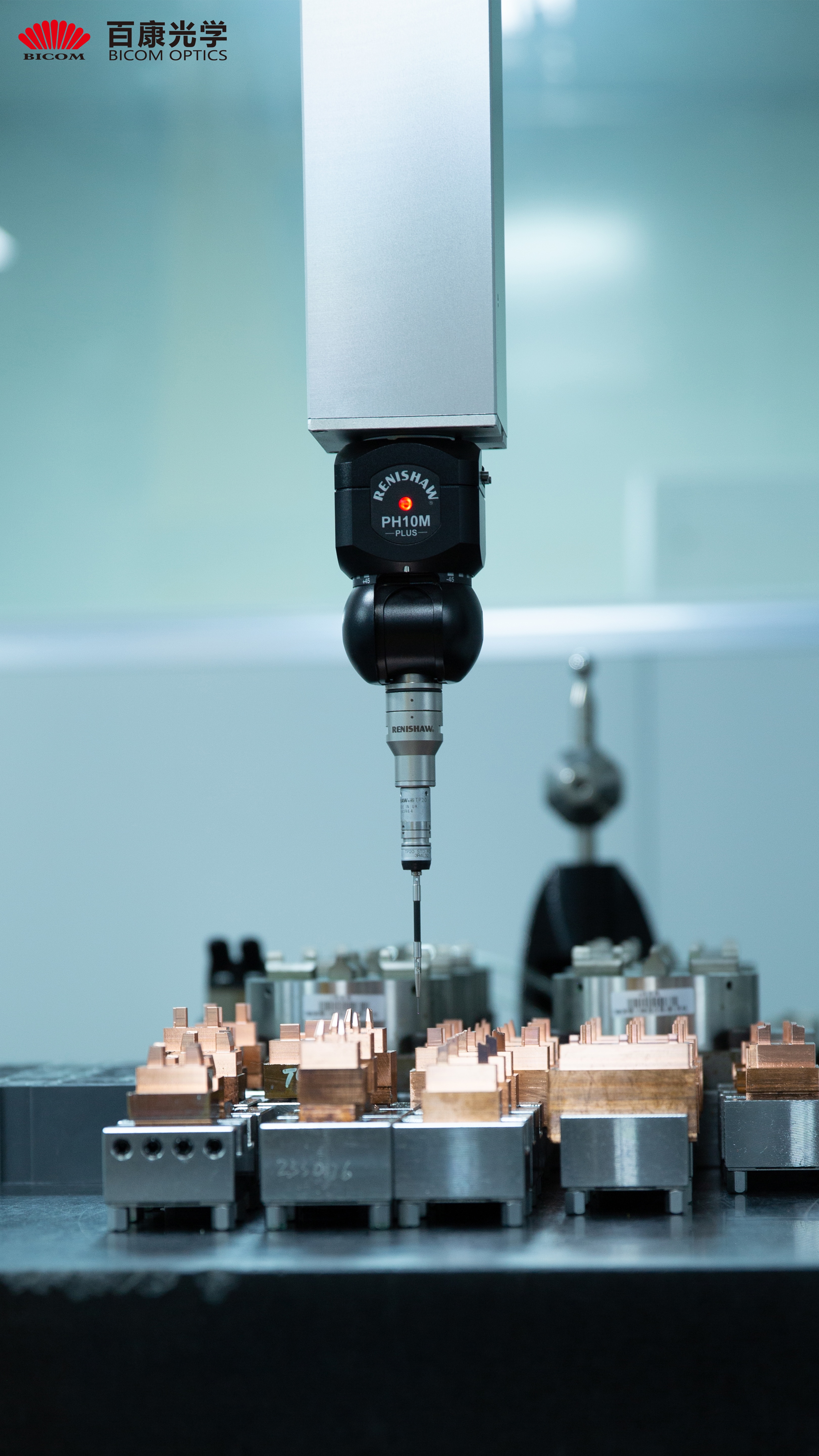
Coordinate measuring machine inspection of mould inserts — the dimensional record behind a moulded optical part.
Material envelopes: where moulded PC and PMMA stop
Custom optical lenses in this product class are produced in optical-grade polycarbonate (PC) or polymethyl methacrylate (PMMA). The published platform parameters are specific and checkable, and they are the fastest way to screen a design for feasibility before any tooling discussion starts.
| Parameter | Optical-grade PC | Optical-grade PMMA |
|---|---|---|
| Operating temperature range | -40 °C to +120 °C | -40 °C to +90 °C |
| Light transmission | Greater than 88% | Greater than 90% |
| Typical selection driver | Higher temperature exposure | Higher transmission requirement |
Table 2. Published material envelope for the Custom Optical Lens / LED Optical Lens / Plastic Optical Lens platform.
Alongside material, the same platform states a size range of 5 mm to 1500 mm, a beam angle range of 2° to 120° covering spot to flood distributions, and support for spot, flood, batwing and asymmetric light distributions, with beam angle and light distribution available as custom parameters. Lens geometry options include aspheric, TIR, Fresnel and freeform types, with surface treatment options covering hard coat, AR and texture, and colour options of clear or diffused.
These are platform-level statements, and that distinction is the point. They tell a buyer what envelope the supplier is set up to mould inside. They do not tell a buyer the optical performance of a specific imaging design, because in imaging, performance is defined by the project’s sensor, working distance, aperture and tolerance budget — and is therefore confirmed through DFM, sampling and validation rather than through a catalogue page.
Bicom Optics: the verifiable part of the capability story
Zhejiang Bicom Optics Co., Ltd operates from Jiashan, Jiaxing, Zhejiang, China, with 700 employees, an R&D team of 50 and an annual output of 90,000,000 pcs. Around 30% of output is exported, with main markets listed as the EU, USA, Middle East, Japan and Korea. The company states that its R&D centre has been recognised as a Research and Development Center of High-tech Enterprises and has received provincial-level awards in Zhejiang, and that it holds over 167 patents, of which 17 are invention patents and 150 are utility model patents.
Manufacturing capability statements relevant to imaging optics include nanoscale CNC machinery with positioning accuracy up to 10 nanometers, mould cavity precision adjustable within 5 microns, high-precision thick-wall lenses up to 50 mm thick, automotive light guides up to 1,300 mm in length, and the ability to manufacture two-colour and three-colour products in a single production run. Production is organised as OEM, ODM and full custom optical design plus injection moulding, with monthly capacity stated at 5,000,000 to 10,000,000 pcs depending on size and complexity.
Management system and product certifications
Certification is where machine vision lens sourcing most often becomes a documentation exercise, so the identifiers matter more than the logos:
- ISO 9001:2015 — certificate 0282Q11279R1M, issued by Zhong An Certification (Beijing Zhong An Zhi Huan Certification Center Co., Ltd.), valid 2025-07-11 to 2028-07-20, covering design and production of lens (including LED lens), lamp mould and sensor products.
- ISO 14001:2015 — certificate 02819E10401R2M, valid 2025-07-11 to 2028-07-23, covering environmental management activities in the design and production of the same product scope.
- ISO 45001:2018 — certificate 02819S10369R2M, valid 2025-07-11 to 2028-07-23.
- ISO 50001:2018 — certificate 04426En00060R001, issued by Beijing Zhongjing Quality Certification Co., Ltd., valid 2026-05-29 to 2029-05-28.
- IATF 16949:2016 — certificate IATF 0549923, issued by SGS, valid 2024-10-15 to 2027-10-14, scoped to the manufacture of LED light lenses and the design and manufacture of LED light modules.
- ECE Conformity of Production — certificate C1 51262503, issued by UCA (Unidad de Certificación del Automóvil) under E/ECE/TRANS/505/Rev.3, valid 2020-03-10 to 2028-03-10, covering retro-reflecting devices, lamps and light signalling devices for power-driven vehicles and their trailers.
- ESG audit completion — issued by MARELLI for the Zhejiang Bicom Optics Co., Ltd Jiaxing Plant, valid 2026-05-12 to 2029-05-11.
The two certificates a machine vision buyer will usually read first are the quality management system certificate and the laboratory accreditation, because together they indicate both process control and the ability to produce measured results in-house.
What CNAS L22447 actually covers
The laboratory holds ISO/IEC 17025:2017 accreditation under certificate CNAS L22447, issued by the China National Accreditation Service for Conformity Assessment, valid 2025-02-06 to 2031-02-05 and applicable to the CN and global markets. The stated scope is testing and calibration laboratory activities for the Custom Optical Lens / LED Optical Lens / Plastic Optical Lens product — and it includes machine vision lens inspection reports and machine vision lens projects.
The same scope extends to dimensional inspection reports, first article inspection of custom optical components, pre-production sample validation, prototype sample inspection reports, batch traceability documentation, precision optical injection moulding, optical mould polished cavity requirements, low-distortion moulded optics, linear optical lens photometric test reports, linear lens beam uniformity testing, multi-lens array optical testing and inspection, custom infrared lens designs, security camera day-night imaging applications, UAV camera lens vibration resistance validation, and projection lens optical performance validation including throw ratio requirements and focal length specifications.
Two practical notes follow from that list. First, accreditation is scope-based: a buyer should confirm that the specific test method their project needs is inside the listed scope, rather than assuming that any test can be issued under the accreditation number. Second, the presence of machine vision lens projects and inspection reports inside the scope is more useful to a procurement file than a general claim of “laboratory tested”, because it names the activity that can actually be documented.
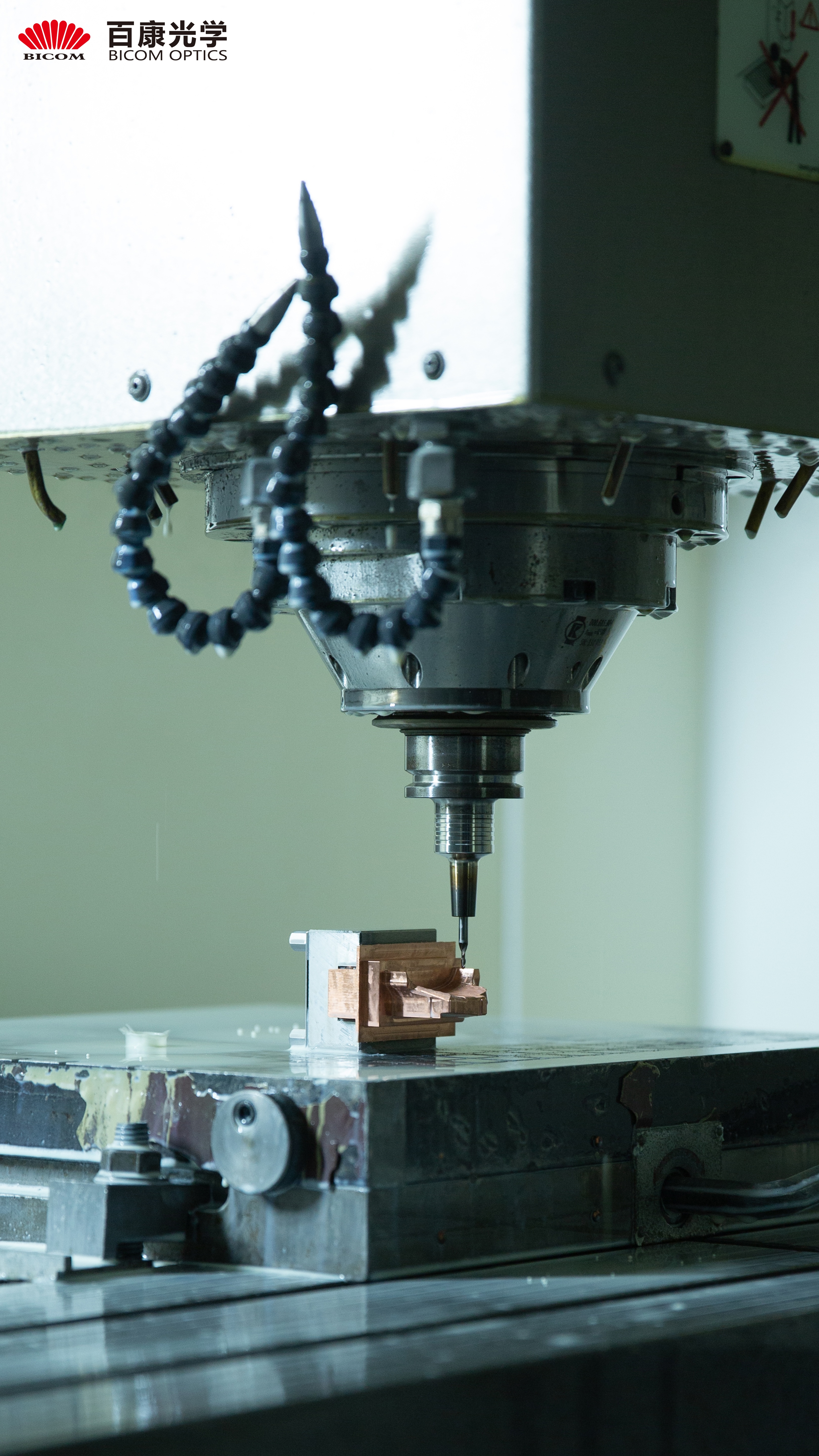
CNC-processed mould inserts: cavity geometry defines the starting point for every moulded lens.
From drawing to validated part: the DFM and sampling chain
For custom optical components, the supplier’s stated workflow runs: requirement confirmation, engineering assessment, DFM, quotation, mould development, T0 sampling, test and validation, optimisation, customer approval, then mass production. Either a prototype mould or a production mould can be used depending on project phase and requirement.
The DFM step is where most of the machine vision risk is either resolved or locked in. Bicom states that DFM assesses product structure and manufacturing feasibility, covering optical surfaces, wall thickness, gates, ejector pins, parting lines, cavity quantity, shrinkage and deformation. The final drawings, optical data and DFM report, mutually confirmed by both parties, become the baseline for mould building, sampling and mass production — with revision control applied so that one revision of the product specification is used throughout the project.
Inputs a buyer is expected to supply are equally concrete: 2D drawings, 3D data, optical data, material requirements, product application and service environment, with detail on dimensions, tolerances, optical surfaces, assembly requirements, surface roughness, light-source information, material grade, working temperature and performance requirements. This is what allows a supplier to evaluate manufacturability, cost and development lead time accurately rather than defensively.
Timing and volume parameters are published: prototype and sample lead time of 7–12 days, mass production delivery of 7–20 days depending on order quantity and complexity, and MOQ in the 1,000–5,000 pcs range, project dependent. Quality control is described as 100% visual inspection, dimensional checks, beam angle and light distribution testing with IES files available, transmission testing, and optional third-party inspection by SGS. Optical design and simulation support is provided through LightTools, TracePro and Zemax, together with IES files, ray-trace data and technical documentation.
Where imaging optics meets illumination optics
Machine vision repeatability is often limited by illumination stability rather than by the lens alone, which is why a supplier that also moulds illumination optics can be useful during evaluation. The Linear Lens DB1102 is described as providing uniform illumination over an elongated lighting zone, reducing local bright spots and dark areas, with a slim elongated profile that can be customised to a luminaire’s length, width and internal space and matched to LED light sources, PCBs and housings. Its stated typical uses include machine vision lighting.
For a vision integrator, the value of that is structural: the illumination optic and the imaging optic can be evaluated against one mechanical interface and one revision baseline. It also keeps the evidence honest, because illumination performance is validated photometrically while imaging performance is validated through image-forming criteria — two different evidence sets, not one interchangeable claim.
Market context: a large lens market, a narrower question
Fortune Business Insights valued the global optical lens market at USD 21.08 billion in 2025. That figure is useful as background for capital and capacity conversations, but it should not be read as a machine vision lens market size: the definition spans ophthalmic and industrial lens segments, and reporting methodologies differ between research houses. No verified figure for machine vision lens demand specifically was available for this analysis, and none is estimated here.
What can be said without a number is directional and widely observed across industrial automation: as inspection points multiply across production lines, demand for imaging optics tends to follow investment in automation equipment rather than consumer lighting cycles. That makes machine vision lens sourcing a longer-cycle decision than a lighting lens purchase — one more reason documentation and revision control deserve to be evaluated as heavily as unit price.
How moulded polymer optics compare with traditional routes
Traditional ground-glass optics remain the reference route for imaging, and the comparison with precision moulded polymer optics is not a case of one replacing the other. The honest comparison is about where each fits.
Moulded PC and PMMA optics make sense where volume, geometry freedom and integrated mounting matter. Multi-cavity tooling allows repeatable production at stated monthly capacity of 5,000,000 to 10,000,000 pcs, freeform and multi-lens array geometries can be produced as single moulded parts rather than assembled from several elements, and colour, diffusion and surface treatment options can be built into the same component. For a vision system that needs thousands of identical optics across a machine fleet, that combination is difficult to match with classical fabrication routes.
The limits are equally real, and buyers should plan around them rather than discover them at validation:
- Thermal envelope. The published operating range is -40 °C to +120 °C for PC and -40 °C to +90 °C for PMMA. Where a machine’s environment exceeds that envelope, moulded PC/PMMA is the wrong starting assumption and the material route needs re-evaluation before design freeze.
- Transmission ceiling. Published transmission is greater than 88% for PC and greater than 90% for PMMA. Where a tighter transmission budget governs the design, that gap has to be absorbed by illumination, exposure or software rather than assumed away.
- Tooling commitment. A moulded optic is a tooling decision. Design changes after tooling require mould or process adjustment under revision control, so late specification changes carry schedule cost that a catalogue purchase does not.
- Minimum order quantity. MOQ is stated at 1,000–5,000 pcs, project dependent. Very small prototype quantities therefore need a different arrangement from the mass production path, and buyers should confirm that arrangement during evaluation rather than after design approval.
- Platform data is not part data. Published size, beam angle and material parameters describe the available envelope. Imaging-specific performance for a given sensor and working distance must be established through DFM, sampling and validated inspection.
Procurement checklist for the evaluation stage
For a buyer moving from research into evaluation, the following requests convert the article above into a comparison file that can be applied consistently across suppliers:
- Revision-controlled drawing and DFM report, signed off by both parties, naming optical surfaces, wall thickness, gates, cavity quantity and shrinkage/deformation assumptions.
- Material grade declaration (PC or PMMA) plus the operating temperature and transmission values the design depends on.
- Tooling capability statement with cavity tolerance and machining accuracy, clearly separated from lens performance claims.
- First article inspection report, prototype sample inspection report and pre-production sample validation record.
- Batch traceability documentation and the in-process control plan covering multiple cavities.
- Laboratory accreditation certificate and confirmation that the required test method sits inside the listed scope.
- Certification set in date at the time of purchase — ISO 9001, ISO 14001, ISO 45001, ISO 50001, IATF 16949 where automotive discipline is relevant, and ECE CoP where the programme requires it.
- Lead time and MOQ confirmation for both the prototype and mass production phases.
Future outlook
The direction of travel in industrial imaging procurement is toward documentable capability. As vision systems spread into more inspection points and more regulated production environments, buyers are asking less about whether a supplier can mould a lens and more about whether the supplier can reproduce the same measured result across cavities, batches and years. Suppliers that already operate accredited laboratories, revision-controlled DFM and traceable batch records are structurally better positioned for that shift than suppliers whose evidence ends at a product photograph.
For Bicom Optics, the credible path is to keep publishing the verifiable layer — certificate numbers, scope statements, material envelopes and validation activities — and to keep imaging-specific performance claims tied to project validation rather than to platform parameters. That is a slower way to communicate, but in machine vision it is the version that survives an audit.
FAQ
What documents are typically required for a custom machine vision lens project?
Customers generally provide 2D drawings, 3D data, optical data, material requirements, product application and service environment. Details cover dimensions, tolerances, optical surfaces, assembly requirements, surface roughness, light-source information, material grade, working temperature and relevant performance requirements. This allows the supplier to evaluate manufacturability, cost and development lead time accurately.
How can a buyer verify a supplier’s genuine custom development capability?
Verification should go beyond drawing-based production. The check is whether the supplier holds full-cycle capability from requirement definition to mass production: optical design, structural evaluation, DFM, mould-flow analysis, mould design and fabrication, precision injection moulding, optical testing and mass-production support. Past custom projects, similar-product experience, engineering team and production equipment are the supporting evidence.
How are specifications and drawings confirmed before mould building?
At project start, customer-provided 2D drawings, 3D files, optical data, materials, dimensional tolerances, appearance and performance requirements are reviewed and confirmed. DFM then assesses product structure and manufacturing feasibility, covering optical surfaces, wall thickness, gates, ejector pins, parting lines, cavity quantity, shrinkage and deformation. The drawings, optical data and DFM report confirmed by both parties become the baseline for mould building, sampling and mass production, with revision control applied to design changes.
What does sampling and validation look like between tooling and mass production?
Custom optical components normally follow: requirement confirmation, engineering assessment, DFM, quotation, mould development, T0 sampling, test and validation, optimisation, customer approval, then mass production. A prototype mould or a production mould can be used depending on project phase. Completed samples are validated for dimensions, optical performance, appearance and assembly against specification, and necessary mould or process adjustments are made based on the results before stable mass production begins.
How is consistency maintained across batches and mould cavities?
Consistency is controlled across raw materials, moulds, injection-moulding processes, dimensional inspection, optical performance and appearance. Stable material supply, multi-cavity mould management, standardised injection-moulding parameters, inspection of critical dimensions and optical performance, complete inspection standards and in-process control keep batches and cavities comparable. Production traceability and continuous process monitoring support timely identification of potential quality risks.
What supply capabilities matter for high-volume custom procurement?
Beyond development competence, buyers should assess long-term stable production and delivery capability: injection-moulding equipment and actual production capacity, multi-cavity mould capability, mould service life, raw-material supply, quality management system, testing capacity, production and engineering teams, lead time and abnormality response. Confirming capacity expansion and supply-chain guarantee capability against order growth, urgent demand and recurring procurement helps mitigate quality, capacity and delivery risk in the mass-production phase.
Closing note
Machine vision lens sourcing rewards the buyer who asks for documents rather than adjectives. A supplier’s certificate numbers, laboratory scope, material envelope and validation workflow can all be checked before tooling is committed — and in imaging, that check is the cheapest risk control available.
Clean-room inspection and assembly area for optical lenses.
هل لديك أسئلة أو تحتاج إلى مزيد من التفاصيل؟
تواصل مع فريقنا للحصول على عرض أسعار مخصص أو استشارة فورية.
طلب عرض أسعار
املأ النموذج أدناه وسيتواصل معك فريقنا بعرض مقترح مخصص.
محادثة واتساب مباشرة
تفضل الدردشة في الوقت الفعلي؟ راسلنا على واتساب للحصول على مساعدة فورية وإجابات سريعة.
- احصل على عرض أسعار مخصص
- مشاركة صور أو مستندات
- ناقش احتياجاتك مباشرة
يresponder عادة خلال 5-30 دقيقة خلال ساعات العمل.