
Metrology 3D Scanner FAQ: Acceptance, ISO 10360, and Inline Inspection
A metrology 3D scanner is a non-contact optical measurement system that captures full-field 3D geometry and converts it into inspection data for CAD comparison, GD&T evaluation, and reporting. In smart manufacturing, the procurement question is not whether a scanner can produce a point cloud; it is whether the measurement result can be accepted, traced, and repeated in an inline production environment. This FAQ addresses the technical and purchasing questions that appear when a buyer moves from a laboratory scanner to an automated inspection cell, with reference to the RobotScan Series, ISO 10360 and VDI/VDE 2634 acceptance, and a documented Thailand mould-inspection case.
When a metrology 3D scanner becomes necessary
A caliper measures a dimension. A metrology 3D scanner measures shape. That distinction matters when a part has freeform surfaces, thin walls, complex edges, or several features that must be checked in one setup. In practical procurement, the scanner becomes necessary when the inspection task requires full-field surface data, when fixture development is slower than the production launch, or when the quality record must be digital and traceable.
Inline inspection raises the requirement further. The scanner must not only capture accurate data; it must work with a robot, a turntable, fixtures, and inspection software without adding unacceptable cycle time or operator dependency. For suitable full-field tasks, SHINING 3D positions non-contact scanning as up to 5–10x faster than caliper-based checks. The documented Thailand case is more conservative, with inspection time falling from 30–45 minutes to 10–15 minutes per part, an approximately 60% efficiency improvement. The difference between a general positioning claim and a specific case is important: buyers should validate speed against their own part mix and tolerance.
Not every measurement needs a 3D scanner. Simple diameter, thickness, or go/no-go checks can still be faster with a gauge. Deep internal bores and hidden features may require a probe or another method because optical scanning needs line of sight. The scanner is most defensible when the cost of missing a shape deviation, building a dedicated fixture, or reconstructing a legacy part is higher than the cost of full-field digital inspection.
What acceptance evidence should be requested before purchase?
Acceptance evidence should be requested before the quotation is finalized, not after the machine arrives. The first question is not whether a supplier says the scanner is accurate; it is which standard part, which test procedure, which artifact, and which laboratory support the accuracy statement. A certificate with a standard name but no part number, test volume, or traceable laboratory scope is difficult to defend in an audit.
VDI/VDE 2634 Part 3 is the primary standard for evaluating the accuracy of optical 3D measuring systems based on area scanning. ISO 10360 is a family of acceptance and reverification standards for coordinate measuring systems, and the applicable part depends on the system type. For example, the OptimScan Q12/Q9 is tested according to VDI/VDE 2634 and ISO 10360-13 in an ISO/IEC 17025 accredited lab, while the OptimScan Q12/Q9 HD is tested to VDI/VDE 2634 Part 2 and ISO 10360. The FreeScan Combo Series, FreeScan UE Nova, FreeScan Omni, FreeScan Trak Nova Series, and FreeScan Combo+ Wireless are tested according to VDI/VDE 2634 Part 3 and ISO 10360, or ISO 10360, in an ISO/IEC 17025 accredited laboratory as applicable to the model.
| Acceptance evidence | Why it matters | What to ask for |
|---|---|---|
| Standard and part number | ISO 10360 and VDI/VDE 2634 are not interchangeable labels. | The exact standard part, test volume, and artifact used for the model. |
| Laboratory accreditation | Accuracy claims should be traceable to a competent laboratory. | ISO/IEC 17025 accreditation scope and calibration certificate. |
| Model and serial number | A certificate for one model does not automatically apply to another. | Certificate tied to the exact scanner or scanner module being purchased. |
| Part-specific correlation | Standard acceptance is not a substitute for measurement system analysis on the production part. | A correlation study using production samples, fixtures, and tolerances. |
The limitation is straightforward: a scanner can pass a standard acceptance test and still be unsuitable for a specific part. Surface finish, fixturing, operator technique, and environmental conditions can change the result. The certificate establishes a metrological baseline; the buyer must still qualify the complete inspection process.
How to choose a scanner for automated inline parts inspection
For inline inspection, selection starts with the cell envelope, not the scanner brochure. Define the largest and smallest part, the weight on the turntable, the features to be measured, the required tolerance, the surface material, the cycle time, and the software handoff. Only then should the scanner and robot configuration be selected.
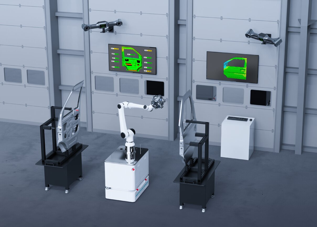
The RobotScan Series is an automation solution that combines a high-accuracy 3D scanner, an industrial robot or collaborative robot, a turntable, fixtures, and control and inspection software. A standard configuration has a measurable object size of up to 500 mm, a turntable load capacity of up to 20 kg, a robot working radius of 800 mm, and a system weight of 70 kg. These are real constraints: a part outside that envelope should not be forced into the standard cell.
| RobotScan configuration | Measurement approach | Best fit |
|---|---|---|
| RobotScan Q12 | Fringe projection technology with high accuracy and detailed data capture. | Small parts with complex surfaces, geometries, or sharp edges, including airfoils, brackets, connectors, gears, housings, and electronic components. |
| RobotScan UE Pro2 | Handheld blue laser scanning with strong material adaptability to black, shiny, and reflective surfaces. | Small and medium sheet metal parts, casting housings, machining parts, and mould components, with wireless or wired connectivity. |
| RobotScan Combo+ | Hybrid light source for versatility across different part types. | Efficient batch inspection of small-to-medium castings and machined parts, mixed-size covers, trim pieces, assemblies, and medium castings. |
The RobotScan Series also offers a fully customizable configuration. Different brands of robotic arm, SHINING 3D scanner, turntable, fixtures, and control and inspection software can be tailored to the application. That flexibility is useful, but it also means the purchase order must define the configuration explicitly. A generic request for an automated 3D inspection cell is not enough.
For parts larger than the standard RobotScan envelope, the FreeScan Trak Nova Series or FreeScan UE Nova may be more appropriate. FreeScan Trak Nova Series provides wireless dynamic tracking and scanning with a flexible field of view up to 2600 x 2200 mm, while FreeScan UE Nova is a large-FOV handheld scanner with a maximum field of view up to 2600 x 2200 mm. The correct choice depends on whether the production concept is a fixed cell or a portable shopfloor workflow.
What purchasing terms and acceptance criteria matter
An inline scanner purchase is a system purchase. The commercial terms should separate the scanner, the robot, the fixtures, the software, the integration, the training, and the after-sales support. Otherwise, a low scanner price can hide integration risk.
| Purchasing term | What to specify | Evidence or reference |
|---|---|---|
| Minimum order | MOQ is 1 unit for the referenced capability. | Confirm in the quotation. |
| Lead time | 30–45 days is stated for the referenced production mode. | Tie lead time to configuration freeze and site readiness. |
| Customization | Logo and automation solution customization are supported under OBM/ODM. | Define robot brand, scanner model, turntable, fixtures, and software. |
| Quality control | 100% test is stated for the referenced capability. | Request the factory test record and acceptance certificate. |
| After-sales | Remote support and onsite support are stated. | Define response time, spare parts, calibration interval, and training scope. |
Acceptance criteria should be written as a sequence: factory acceptance test, site acceptance test, part-specific correlation, operator training, and production release. The factory test confirms the scanner and cell build; the site test confirms integration with the buyer's environment; the part-specific correlation confirms that the measurement process can distinguish good and bad parts at the required tolerance. A purchase order that only says ISO 10360 or VDI/VDE 2634 is incomplete because it does not define the part, the fixture, or the acceptance volume.
ISO 10360 vs VDI/VDE 2634 in a procurement conversation
ISO 10360 and VDI/VDE 2634 are related to metrological acceptance, but they are not interchangeable in a specification. VDI/VDE 2634 Part 3 is explicitly used for optical 3D measuring systems based on area scanning. ISO 10360 is a family of acceptance and reverification standards for coordinate measuring systems, and the applicable part depends on the system type. A procurement document should therefore name the standard part, the test procedure, the artifact, and the laboratory.
The practical difference appears in the certificate review. A statement that a scanner is ISO 10360 compliant is less useful than a certificate stating which part of ISO 10360 was applied, which test volume was used, and which ISO/IEC 17025 accredited laboratory performed the test. The same logic applies to VDI/VDE 2634 Part 3. The buyer should be able to connect the certificate to the exact model and serial number in the quotation.
SHINING 3D uses an ISO/IEC 17025 accredited Accuracy Lab for calibration and verification. That matters because the lab accreditation is part of the evidence chain. It does not mean that every scanner model has identical certificates or identical test volumes. The OptimScan Q12/Q9, OptimScan Q12/Q9 HD, FreeScan Combo Series, FreeScan UE Nova, FreeScan Omni, FreeScan Trak Nova Series, and FreeScan Combo+ Wireless each have their own acceptance basis and certificate scope. The buyer should request the document set for the selected model.
Can SHINING 3D issue accuracy certificates according to ISO 10360 or VDI/VDE 2634?
Yes, subject to the actual certificates issued. SHINING 3D scanners provide inspection reports and calibration certificates traceable to international standards such as VDI/VDE 2634 and ISO 10360. All calibration and verification procedures are performed in SHINING 3D's accredited Accuracy Lab, which operates in accordance with ISO/IEC 17025 requirements. The certificate scope depends on the product and the standard part applied.
For example, the OptimScan Q12/Q9 is tested according to VDI/VDE 2634 and ISO 10360-13 in an ISO/IEC 17025 accredited lab. The OptimScan Q12/Q9 HD is tested to VDI/VDE 2634 Part 2 and ISO 10360. The FreeScan Combo Series is tested according to VDI/VDE 2634 Part 3 and ISO 10360. The FreeScan UE Nova, FreeScan Omni, and FreeScan Trak Nova Series meet acceptance test standards VDI/VDE 2634 Part 3 and ISO 10360. The FreeScan Combo+ Wireless accuracy test is ISO 10360 certified and performed in an ISO/IEC 17025 accredited Accuracy Lab.
The buyer should verify four items: the exact model and serial number, the standard part number, the test volume or artifact, and the accreditation scope of the laboratory. A certificate is an acceptance baseline, not a guarantee that the scanner will meet every part tolerance without process qualification. For inline inspection, the scanner certificate should be paired with a cell-level acceptance record.
What the RobotScan Series contributes to inline inspection
The RobotScan Series is best understood as an automation platform rather than a single scanner. It combines a high-accuracy 3D scanner, an industrial robot or collaborative robot, a turntable, fixtures, and control and inspection software. The scanner can be a RobotScan Q12 with fringe projection, a RobotScan UE Pro2 with blue laser scanning, or a RobotScan Combo+ with hybrid light source. The choice depends on part geometry, surface finish, and the balance between detail and speed.
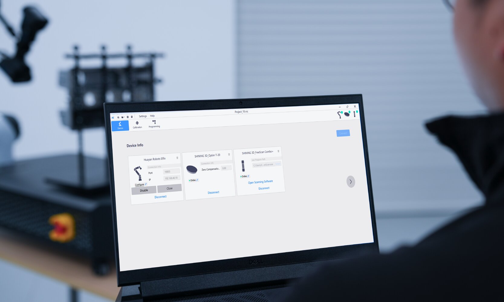
For production, the control software is as important as the optical head. The cell must move the robot, trigger the scan, align the data, compare it with CAD, and produce a report without introducing manual steps that erode repeatability. SHINING3D Inspect is PTB-certified and can support comparison, cross-section, feature, dimension, gauge, report, and quick measurement functions. The scanner data can also be used with PolyWorks, Geomagic Control X, EXModel Pro, Geomagic Design X, and BlueStar Mapping depending on the workflow.
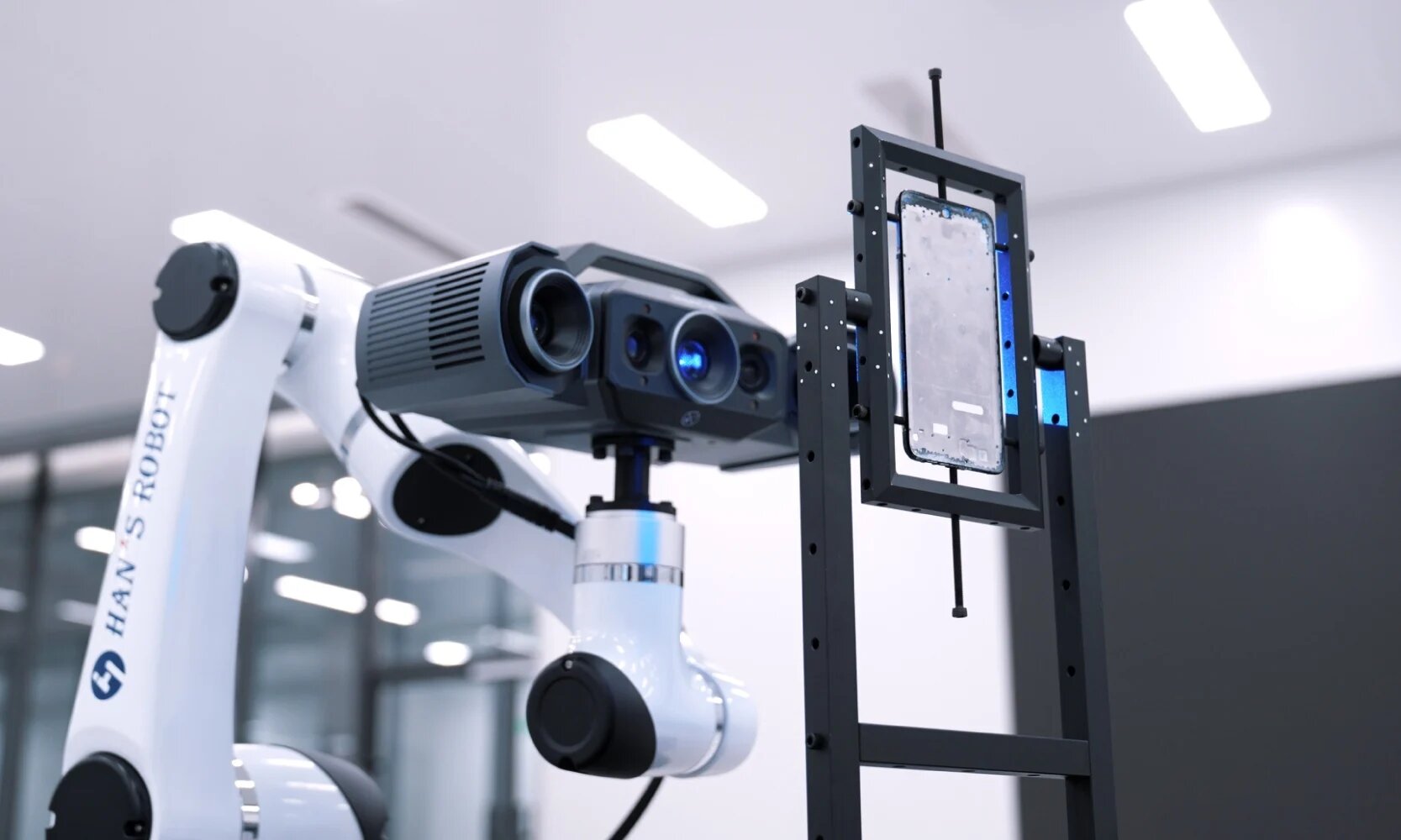
The industrial reliability argument is not only about the scanner head. It includes the robot repeatability, the fixture stability, the turntable load, the software version, and the calibration schedule. A RobotScan cell with a 20 kg turntable and an 800 mm robot working radius is a defined production asset. It should be accepted as a system, not as a collection of components.
Application fit and a Thailand mould-inspection case
Metrology 3D scanning is used in automotive, aerospace, energy and heavy industry, marine, medical, consumer electronics, mould manufacturing, and MRO. In automotive, typical tasks include body and component inspection, stamping die inspection, welding inspection, and battery-pack quality control. In aerospace, the focus is on structural and component inspection, MRO, and blade inspection. In mould manufacturing, the need is often reverse engineering, wear analysis, and dimensional verification of complex cavities.
A documented Thailand case shows how the workflow works outside a laboratory. A manufacturer of high-precision moulds and customized industrial equipment used one FreeScan Trak ProW unit for more than one year. The system provided marker-free scanning and wireless operation, with accuracy up to 0.023 mm. Inspection time fell from 30–45 minutes to 10–15 minutes per part, improving overall 3D inspection efficiency by approximately 60%. The scan data integrated with CAD/CAM workflows and supported reverse engineering, quality inspection, and design validation.
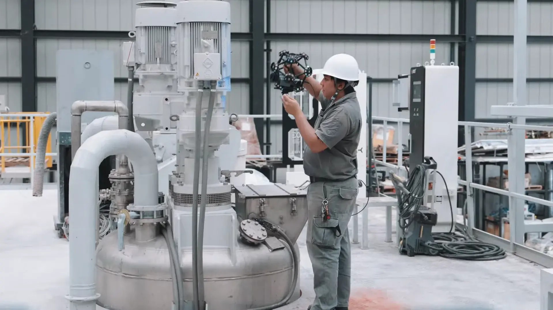
The case is relevant to inline inspection because it shows where the time saving comes from. It is not only scan speed. Marker-free tracking reduces preparation, wireless operation reduces cable management, and the data can move directly into CAD/CAM and inspection software. The same principles apply when the scanner is mounted on a robot, although the cell adds robot programming and fixture design to the workflow.
Market trend: from laboratory measurement to production evidence
The direction of the market supports the move toward inline optical inspection, but the figures should be read with care because definitions vary. The global 3D scanning market was estimated at USD 4.28 billion in 2024, with laser scanners accounting for 45.3% of total revenue, according to Grand View Research. The global 3D metrology market was valued at USD 11.13 billion in 2024 and is projected to reach USD 15.01 billion by 2029, according to MarketsandMarkets. These are different market definitions, not competing estimates of the same number.
Adoption is concentrated in sectors where geometric deviations are expensive. The automotive sector represented the largest end-user segment for 3D scanning in 2024, using scanners for inline inspection and reverse engineering. EV battery-pack tolerances as tight as 0.025 mm are driving automakers to replace manual gauges with automated optical scanners. Reverse engineering also remained a dominant application in 2024 because legacy part digitization and product redesign continue to create demand for full-field data.
For procurement, the implication is that a scanner is increasingly evaluated as part of a digital quality system. The value is not just a faster measurement; it is a traceable record that can be compared, stored, and audited. That is why acceptance evidence, software compatibility, and calibration scope are becoming as important as the accuracy headline.
Comparison with calipers and CMMs
Calipers, CMMs, and metrology 3D scanners solve different measurement problems. A caliper is a point tool. A CMM is a tactile coordinate system with strong accuracy and a mature programming workflow. A 3D scanner is a full-field optical system that captures surface geometry quickly but depends on line of sight and surface conditions.
| Method | Strength | Boundary |
|---|---|---|
| Calipers and manual gauges | Fast for simple dimensions, low cost, familiar to operators. | Point-based; misses full-field shape, warpage, and complex freeform deviation. |
| CMM | High accuracy, mature traceability, strong for prismatic features and GD&T. | Contact measurement, programming and fixturing can take days for complex parts, and thin or soft parts may deform. |
| Metrology 3D scanner | Full-field data, non-contact capture, fast digital model, suitable for complex surfaces and reverse engineering. | Line-of-sight limitation, surface finish sensitivity, object envelope constraints, and the need for part-specific process qualification. |
The comparison should not be reduced to a single winner. A production line may use calipers for incoming checks, a CMM for final arbitration, and a 3D scanner for full-field inspection and digital archiving. The procurement question is which method provides the required evidence at the required cycle time and cost. In many inline cells, the scanner wins because it captures the whole surface without a dedicated fixture; in others, a CMM or gauge remains the more defensible tool.
Limitations and trade-offs
- Object envelope: a standard RobotScan cell has a measurable object size of up to 500 mm and a turntable load of up to 20 kg. Larger or heavier parts require a different configuration or a portable scanner.
- Line of sight: optical scanning cannot see inside closed internal features. Deep bores, undercuts, and hidden surfaces may need a probe or another measurement method.
- Surface condition: black, shiny, and reflective surfaces are more difficult for some optical systems. Blue laser and hybrid light source configurations improve material adaptability, but the surface still needs to be validated.
- Acceptance scope: ISO 10360 or VDI/VDE 2634 certificates confirm the scanner's metrological basis, not the capability of the complete inline cell. Part-specific correlation is still required.
- Operating discipline: calibration, software versions, fixture maintenance, and operator training are part of the measurement chain. A scanner that is accurate on delivery can drift if the process is not controlled.
These limits do not weaken the case for optical inspection; they define where it should be used. The strongest procurement decision is the one that states both the capability and the boundary.
Future outlook
The next phase of inline metrology will be less about a single accuracy number and more about the evidence chain. Buyers will ask for a scanner certificate, a cell acceptance record, a part-specific correlation study, and a software audit trail. They will also ask how the system behaves when the part changes, when the operator changes, and when the production environment is not a laboratory.
SHINING 3D's product direction reflects that shift. The FreeScan Omni Series includes PTB-certified on-device inspection, which moves part of the inspection workflow onto the scanner itself. The FreeScan Trak Nova Series uses wireless dynamic tracking and video photogrammetry to reduce marker preparation for large parts. RobotScan configurations can be customized with different robot brands, scanners, turntables, fixtures, and software. The common thread is not simply faster scanning; it is a more complete digital measurement workflow.
For procurement teams, the practical conclusion is to specify the measurement chain rather than the scanner alone. Define the part envelope, tolerance, surface, fixture, software, acceptance standard, certificate, and support model. That specification will remain useful even as scanner hardware improves.
Reference document: SHINING 3D 3D Digitizing introduction.
FAQ
When is a metrology 3D scanner needed instead of calipers or a CMM?
A metrology 3D scanner is needed when the inspection task requires full-field surface data rather than a few point dimensions. It is a better fit for freeform surfaces, thin or flexible parts, complex edges, and cases where fixture development would delay production. Compared with calipers, it captures shape and warpage that point tools can miss. Compared with a CMM, it is faster for complex surfaces and does not require contact, but it relies on line of sight and may not replace a CMM for every prismatic or internal feature. The decision should be based on the tolerance, part geometry, cycle time, and required traceability.
How do I choose a metrology 3D scanner for automated inline parts inspection?
Start with the cell envelope: part size, weight, surface, features, tolerance, and cycle time. For a standard RobotScan cell, the measurable object size is up to 500 mm, the turntable load is up to 20 kg, and the robot working radius is 800 mm. Then select the scanner type: RobotScan Q12 with fringe projection for small complex parts, RobotScan UE Pro2 with blue laser for black, shiny, or reflective surfaces, or RobotScan Combo+ with hybrid light source for mixed parts. Confirm the control software, inspection software, fixture design, and acceptance criteria before purchase. If the part exceeds the cell envelope, consider FreeScan Trak Nova Series or FreeScan UE Nova instead.
What acceptance criteria should a purchase order include for ISO 10360 or VDI/VDE 2634?
The purchase order should name the exact standard part, test volume, artifact, and laboratory. It should require a certificate tied to the model and serial number, an ISO/IEC 17025 accreditation reference, and a factory acceptance test. For an inline cell, it should also require a site acceptance test and a part-specific correlation study using production samples and fixtures. A generic statement that the scanner is ISO 10360 or VDI/VDE 2634 compliant is not sufficient. The acceptance record should show which standard was applied and how the result connects to the purchased configuration.
Can SHINING 3D issue an accuracy certificate according to ISO 10360 or VDI/VDE 2634?
Yes, subject to the actual certificates issued. SHINING 3D scanners provide inspection reports and calibration certificates traceable to international standards such as VDI/VDE 2634 and ISO 10360. Calibration and verification are performed in SHINING 3D's ISO/IEC 17025 accredited Accuracy Lab. The exact certificate depends on the model: OptimScan Q12/Q9 is tested according to VDI/VDE 2634 and ISO 10360-13, OptimScan Q12/Q9 HD to VDI/VDE 2634 Part 2 and ISO 10360, and the handheld and tracking models such as FreeScan Combo Series, FreeScan UE Nova, FreeScan Omni, and FreeScan Trak Nova Series to VDI/VDE 2634 Part 3 and ISO 10360. Buyers should request the certificate for the exact model and serial number.
What are the limits of a RobotScan inline inspection cell?
A standard RobotScan cell has a measurable object size of up to 500 mm, a turntable load of up to 20 kg, a robot working radius of 800 mm, and a system weight of 70 kg. These limits define the part family that can be handled without a custom configuration. Optical scanning also requires line of sight, so deep internal features may need a probe or another method. Surface finish can affect data quality, although blue laser and hybrid light source configurations improve adaptability. Finally, the scanner certificate does not replace part-specific correlation. The cell should be accepted as a system with fixtures, software, and production samples.
How does the Thailand FreeScan Trak ProW case relate to inline inspection?
The Thailand case involved a manufacturer of high-precision moulds and customized industrial equipment that used one FreeScan Trak ProW unit for more than one year. The system provided marker-free, wireless scanning with accuracy up to 0.023 mm. Inspection time fell from 30–45 minutes to 10–15 minutes per part, improving overall 3D inspection efficiency by approximately 60%, and the data integrated with CAD/CAM workflows for reverse engineering, quality inspection, and design validation. The case is relevant to inline inspection because it shows how preparation time, cable management, and data handoff affect total inspection time, not only scan speed. It does not replace a cell-level acceptance test for a robot-mounted installation.
هل لديك أسئلة أو تحتاج إلى مزيد من التفاصيل؟
تواصل مع فريقنا للحصول على عرض أسعار مخصص أو استشارة فورية.
طلب عرض أسعار
املأ النموذج أدناه وسيتواصل معك فريقنا بعرض مقترح مخصص.
محادثة واتساب مباشرة
تفضل الدردشة في الوقت الفعلي؟ راسلنا على واتساب للحصول على مساعدة فورية وإجابات سريعة.
- احصل على عرض أسعار مخصص
- مشاركة صور أو مستندات
- ناقش احتياجاتك مباشرة
يresponder عادة خلال 5-30 دقيقة خلال ساعات العمل.