Non-Standard HV Main Transformer Parameters for North America: An ODM Integration Workflow
A North American main power transformer is an engineered item, not a catalog purchase. Percent impedance, guaranteed loss levels, tap-changing arrangement, and the accessory set that links the unit to protection, monitoring and site infrastructure are fixed by the project electrical design long before a supplier is shortlisted. What follows is a working reference for procurement and engineering teams on how those four parameter groups are specified for North American high-voltage projects, how they are carried through an ODM workflow from technical clarification to factory acceptance, and where customization stops being an advantage.
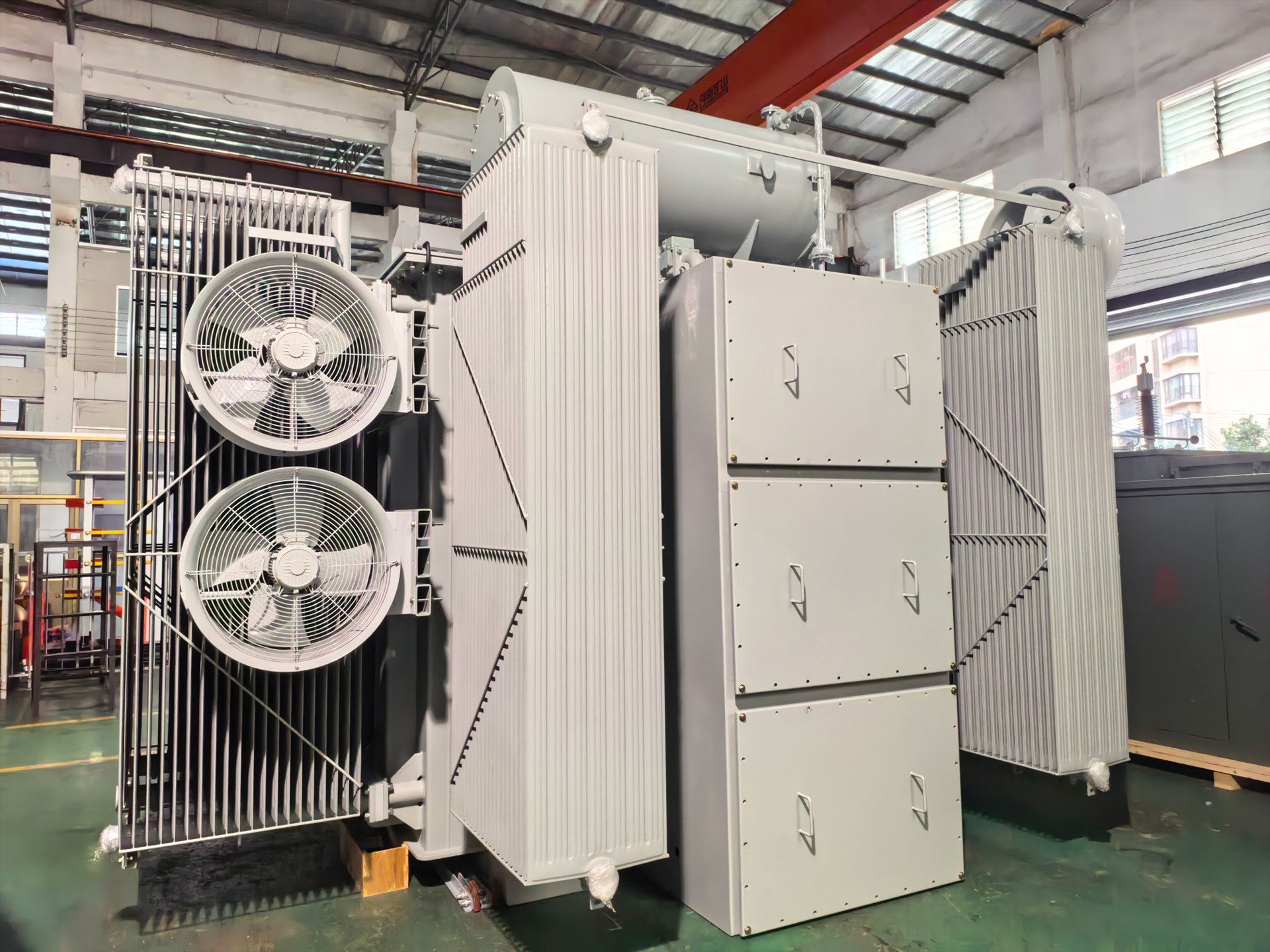
Why Parameter Definition Now Sets the Project Schedule
Grid-side capital programs have moved substation transformers from a repeat purchase to a long-lead engineered item. The global substations market was valued at USD 128.5 billion in 2024 and is expected to reach USD 178.9 billion by 2034, a CAGR of 3.2%, according to Global Market Insights. The wider transformer market was estimated at USD 64.64 billion in 2025 and is projected to reach USD 88.48 billion by 2030, according to MarketsandMarkets. Data center load growth is a separate driver: the data center transformer market is expected to rise from USD 2.2 billion in 2023 to USD 5.9 billion by 2030 at a 10% CAGR, according to Strategic Market Research.
Technology choice has not shifted as quickly as demand. Grand View Research places oil-immersed transformers at approximately 59.3% of the power transformer segment in 2025, citing cooling efficiency and durability in utility applications. For most utility and large industrial substation duties in North America, the liquid-filled unit remains the default platform on which non-standard parameters are then layered.
That combination — rising volume, long production cycles and a liquid-filled default — is why parameter clarity has become a form of schedule control. A specification that leaves impedance open until after award, or that treats loss levels as a purely commercial detail, generally returns as a change request during design review.
The Four Parameter Groups Buyers Must Lock Before ODM Engagement
Winley Electric, a transformer manufacturer headquartered in Xiamen, China and certified to UL and cUL, provides OEM and ODM manufacturing for Substation Power Transformers rated up to 100 MVA and 230 kV. Its stated customization scope covers capacity, voltage ratio, winding configuration, impedance, loss levels, cooling method, tap-changing system, terminal arrangement, protection and monitoring functions, structural design, testing, documentation and transportation requirements. The four parameter groups below are the ones that most often decide whether a custom build integrates cleanly on a North American site.
1. Percent impedance: the parameter that couples the transformer to the grid
Impedance is the electrical bridge between the transformer and everything around it. It sets the magnitude of through-fault current, influences how protection is coordinated, determines how load divides between paralleled units, and interacts with voltage regulation during motor starting or rectifier loading. On retrofit and expansion projects, the new unit frequently has to operate alongside existing transformers, and impedance becomes a design input rather than a selected option.
Impedance is also coupled to other requirements. Lower-loss designs and compact footprints constrain how far impedance can be adjusted inside a given tank, and short-circuit withstand has to be maintained regardless of the target value. In practice this trade-off belongs in design review, not in post-award negotiation.
2. Loss levels: the two commercially weighted numbers
No-load loss and load loss are usually the most heavily weighted technical values in a North American tender because they feed capitalized-cost calculations over the transformer lifetime. Winley Electric's routine test program for substation power transformers includes winding resistance, turns ratio, polarity and phase relation, and no-load loss measurement before delivery, under ISO 9001 process management with dedicated QC oversight. The company states that its products are built to ANSI/IEEE/CSA/DOE2016/IEC60076 and other standards, so loss-level commitments sit inside a defined test and documentation framework rather than being verified informally.
3. Tap-changing system: matching regulation to the operating regime
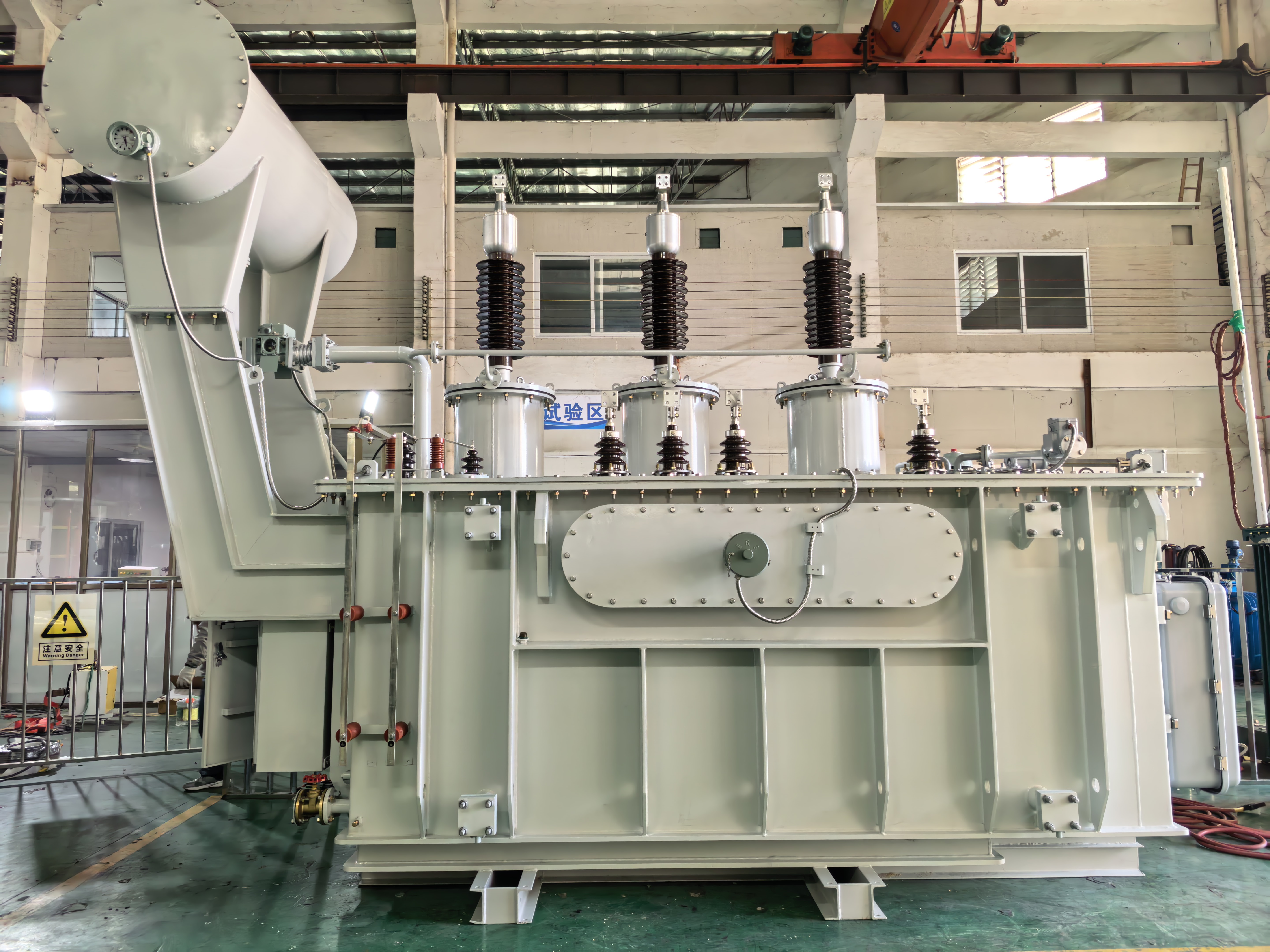
Tap changers separate a standard unit from a grid-ready one. De-energized tap changers suit seasonal or planned voltage adjustment; on-load tap changers are used where the transformer must regulate voltage while energized, which is typical of utility interconnections and long feeders. Component sourcing is part of the same decision: Winley Electric's ODM scope allows customer-specified components from recognized brands such as Maschinenfabrik Reinhausen (MR), Qualitrol, and the Eaton Cooper Power series to be integrated so that the delivered unit matches the owner's standards and maintenance preferences.
4. Accessory and interface integration
Terminal arrangement, protection and monitoring functions, structural design, testing, documentation and transport requirements complete the specification. On North American projects these items are shaped by the standard families the site is engineered around: the IEEE C57 series primarily governs substation transformer design in the region, while UL 1561 and UL 1562 apply to liquid-filled and dry-type units respectively, according to a published comparison by Emirates Transformer & Switchgear. Winley Electric's products hold UL and cUL certification along with ISO, CE, TUV and EMC listings, which allows accessory and interface decisions to be made against a known compliance baseline.
| Parameter group | Typical buyer input | What it changes in the design | Where it is confirmed |
|---|---|---|---|
| Percent impedance | Target impedance at a stated rating and temperature rise; whether the unit must parallel with existing transformers | Core and winding geometry, clearances, short-circuit withstand, load-sharing behaviour in parallel operation | Design review, then routine testing before delivery |
| Loss levels | Guaranteed no-load loss and load loss referenced to the applicable project efficiency requirement | Core material grade and build, winding conductor, cooling arrangement | No-load loss measurement within the routine test sequence |
| Tap-changing system | Voltage range, step count, and whether regulation is required under load | Tap winding design, diverter switch or de-energized link arrangement, control interface | Drawing approval, factory routine tests, acceptance testing |
| Accessories and interfaces | Terminal arrangement, protection and monitoring functions, specified component brands, documentation and transport requirements | Bushing and cable-box configuration, monitoring provisions, tank and enclosure design | Drawing approval, factory acceptance, documentation handover |
The ODM Docking Workflow, Stage by Stage
ODM docking is less about manufacturing and more about sequencing decisions so that manufacturing starts against a frozen design. The workflow below reflects the process stages Winley Electric describes for customized substation power transformers, from selection support through installation guidance.
- Technical clarification. The project specification, site conditions, existing equipment interfaces and applicable standards are translated into a parameter list — capacity, voltage ratio, winding configuration, impedance, loss, cooling and tap-changing requirements.
- Selection recommendation. A rating and configuration proposal is issued for engineering confirmation, including the platform class and cooling method.
- Drawing design. Outline drawings, terminal arrangement, protection and monitoring provisions and structural details are prepared for approval. This is the stage where accessory brands and interface points are fixed.
- Accessory selection. Customer-specified components — for example MR tap changers, Qualitrol devices or Eaton Cooper Power series parts — are confirmed against project standards and maintenance preferences.
- Design freeze and documentation. The approved drawing set, test plan and documentation package are locked, and the transport plan is defined for the specific unit mass and route.
- Manufacturing and quality control. Production runs under ISO 9001 process management with dedicated QC oversight, using equipment that includes silicon steel sheet slitting and cross-cutting lines, multi-model foil and wire winding machines, vacuum constant-temperature drying ovens, two-stage vacuum oil filters and automated welding equipment.
- Routine testing and acceptance support. Every unit undergoes routine testing before shipment, including winding resistance, turns ratio, polarity and phase relation, and no-load loss. Factories also operate type-test equipment such as lightning impulse test devices, and acceptance support is provided to the buyer's inspection team.
- Transport and installation guidance. A project-specific transport plan and installation guidance are issued, and 24/7 technical support remains available after delivery. Warranty coverage runs 24 months from the bill of lading, with free replacement of damaged accessories on photo evidence and free supply of consumable accessories based on unit quantity.
Lead-Time Planning for a Custom Build
Customization changes engineering effort, not the physics of production capacity. Winley Electric indicates a monthly capacity of 300 units with a minimum order quantity of one unit, so single-project custom builds are accepted. Indicated production lead times scale with rating as follows.
| Rating band | Indicated production lead time |
|---|---|
| Below 10 MVA | 8–10 weeks |
| 10–40 MVA | 10–12 weeks |
| 40–100 MVA | 18–20 weeks |
Documented project outcomes show how these bands translate in practice. In one U.S. utility project, regional lead times for 30–50 MVA liquid-filled substation transformers were reported to extend beyond 100 weeks, while the two 40 MVA conservator-type liquid-filled step-down transformers built for that project completed a 12-week in-house production and testing cycle. Two 10–14 MVA custom units for a U.S. EPC client were manufactured within a 9-week production cycle. Two 34 MVA units with 304 stainless steel construction and NEMA 4X weatherproof enclosures were completed in 12 weeks for a U.S. electrical contractor. A single 8 MVA unit for a U.S. renewable energy developer was delivered on a 90-day lead time, and two 6,500 kVA oil-immersed step-up transformers for a Honduras solar plant were delivered in 7 weeks.
Where Non-Standard Main Transformers Are Used in North America
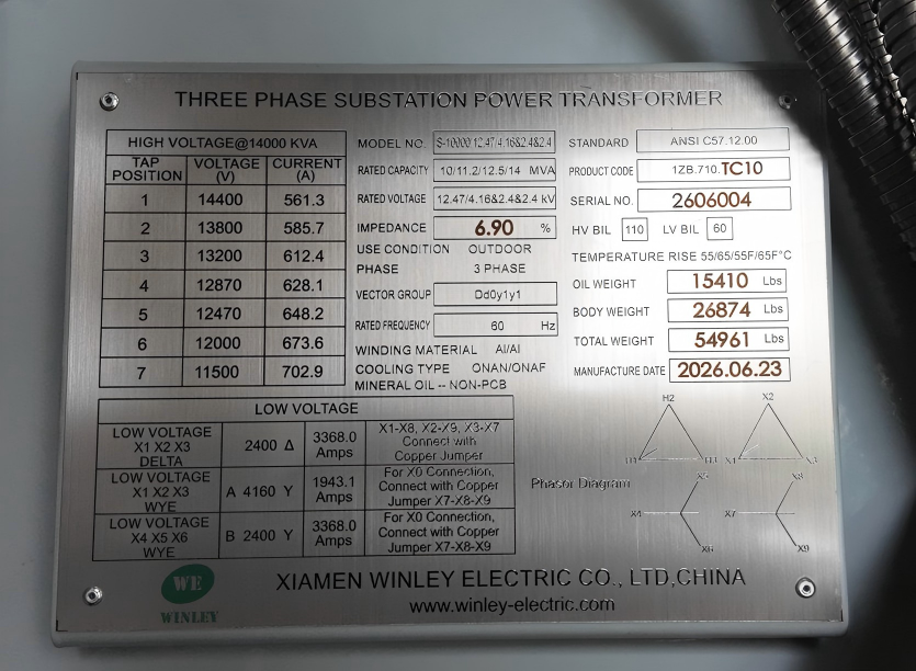
- Industrial substations with multiple medium-voltage buses. A U.S. EPC client required multiple 2.4 kV and 4.16 kV secondary feeders for medium-voltage motors and process loads. The delivered solution used a Dd0y1y1 winding configuration with multiple secondary outputs, so one transformer platform supported several distribution buses and industrial loads.
- Utility grid modernization and aging substation replacement. Two 40 MVA conservator-type liquid-filled step-down transformers were engineered to ANSI/IEEE requirements, with project-specific logistics support for heavy units.
- Data centers and digital infrastructure. These applications operate 24/7 with dual-source supply and N+1 or 2N redundancy, stepping medium-voltage power down to UPS systems, server halls and cooling equipment. The requirement set is harmonic tolerance, low losses, low noise, condition monitoring and rapid fault response.
- Renewable interconnection. An 8 MVA unit for a U.S. developer used a dual low-voltage split-winding architecture with high thermal margin insulation and harmonic load resistance, delivering stable 34.5 kV output with IEEE C57 compliance for combined solar and storage dispatch. Solar, wind and BESS applications share step-up duty, reverse power flow and frequent load cycling.
- Commercial, institutional and campus distribution. On these sites the transformer converts 34.5 kV, 24.94 kV, 13.8 kV or 4.16 kV power to 480Y/277 V for HVAC, lighting and elevators, under constraints such as low audible noise, compact footprint and underground loop-feed compatibility.
Market Signals Worth Writing Into the Specification
- Monitoring is becoming standard content. The smart transformer market is projected to grow from USD 3.17 billion in 2025 to USD 10.15 billion by 2035 at a CAGR of 12.35%, according to SNS Insider. Buyers specifying monitoring provisions at design stage avoid retrofitting sensors onto a long-life asset.
- Liquid-filled remains the base case. With oil-immersed designs at roughly 59.3% of the power transformer segment in 2025, the practical question is not which insulation medium to choose, but which parameters to specify within it.
- Supply concentration matters. Grand View Research puts Asia Pacific at approximately 41.1% of global transformer revenue in 2025. For North American buyers, that makes documented standards compliance and verifiable test records a sourcing requirement rather than a preference.
- Standard families are the common language. IEEE C57, UL 1561 and UL 1562 give the buyer and the manufacturer the same reference points when a non-standard parameter set has to be justified to an inspection authority or a utility reviewer.
Custom ODM Versus Standard Catalog Procurement, and Where the Approach Stops
| Consideration | Standard catalog procurement | Non-standard ODM build |
|---|---|---|
| Parameter fit | Limited to published ratings, impedance bands and accessory sets | Impedance, loss, winding configuration, cooling and tap-changing system are set per project |
| Retrofit and parallel operation | Site-side mitigation may be needed where impedance or footprint does not match existing units | Parameters can be aligned to existing units and constrained sites |
| Engineering cycle | Shorter, because configuration is fixed | Longer: technical clarification, drawing design and documentation precede manufacturing |
| Component sourcing | Supplier's standard accessory set | Customer-specified components such as MR, Qualitrol and Eaton Cooper Power series parts can be integrated |
| Schedule risk profile | Low engineering risk; rating availability governs the date | Engineering risk drops once parameters are frozen; third-party long-lead items remain a dependency |
Customization is not free of boundaries, and buyers should plan for them explicitly. Winley Electric's substation power transformer platform covers ratings up to 230 kV and 100 MVA; projects above that voltage class fall outside the platform. Within the platform, lead time scales with rating, with 18–20 weeks indicated for 40–100 MVA units, and a customized parameter set adds design review and documentation steps that a fixed catalog order does not carry. Customer-specified long-lead components such as tap changers and monitoring devices remain dependent on those suppliers' own delivery schedules. Custom impedance and loss packaging also does not replace the buyer's grid interconnection study or the utility's protection coordination review, which stay on the project side.
Future Outlook
The direction of North American substation work suggests three changes for parameter-level sourcing. First, monitoring and condition data will migrate from add-on options into the base specification, consistent with the growth trajectory of the smart transformer segment. Second, documentation will carry more weight in supplier evaluation, because a custom unit has to be justified to utilities, inspectors and insurers through drawings and test records rather than through a catalog page. Third, buyers are likely to separate two decisions that were previously merged: which parameters must be non-standard for technical reasons, and which can stay standard to protect the schedule.
For manufacturers, the corresponding capability is not the ability to quote a wide range, but the ability to run a disciplined clarification-to-acceptance sequence. For buyers, the practical takeaway is that the parameter sheet is a deliverable in its own right — one worth completing before the commercial process begins.
Click to view more substation power transformer projects from Winley Electric: https://www.winley-electric.com/supplier-4803516-substation-power-transformer
·Website:www.winley-electric.com
FAQ
What determines the percent impedance of a custom substation transformer?
Impedance is determined by the project's electrical design rather than by a catalog value. It is set by through-fault current limits, protection coordination, the need to parallel with existing transformers, and voltage regulation under motor-starting or rectifier loads. Winley Electric supports project-specific customization of impedance for Subsation Power Transformers rated up to 100 MVA and 230 kV, and the final value is confirmed during design review because it interacts with loss level, short-circuit withstand and physical size.
Which loss values should be specified, and how are they verified?
Two values are typically specified: guaranteed no-load loss and load loss, referenced to the efficiency requirement applicable to the project. Winley Electric's products are built to ANSI/IEEE/CSA/DOE2016/IEC60076 and other standards, and every unit undergoes routine testing before delivery that includes winding resistance, turns ratio, polarity and phase relation, and no-load loss measurement, under ISO 9001 process management with dedicated QC oversight.
When is an on-load tap changer required instead of a de-energized tap changer?
An on-load tap changer is used where the transformer must change taps while energized, which is typical of utility interconnections and long feeders with wide voltage variation. A de-energized tap changer is sufficient for seasonal or planned voltage adjustment made while the unit is offline. Both arrangements sit inside Winley Electric's customization scope, and customer-specified tap changer components from brands such as Maschinenfabrik Reinhausen (MR) can be integrated to match maintenance preferences.
Can third-party accessories be integrated during an ODM build?
Yes, when they are specified at clarification stage. Winley Electric's ODM manufacturing permits customer-specified components from recognized brands including Qualitrol, the Eaton Cooper Power series, and Maschinenfabrik Reinhausen (MR) to be integrated alongside project-specific terminal arrangement, protection and monitoring functions, structural design, testing and documentation requirements. Name-brand component integration supports alignment with the owner's existing maintenance and spares strategy.
What lead time should a North American buyer plan for a large custom unit?
Winley Electric indicates 8–10 weeks for transformers below 10 MVA, 10–12 weeks for 10–40 MVA units, and 18–20 weeks for 40–100 MVA units, with a minimum order quantity of one unit and monthly capacity of 300 units. Documented project examples include two 10–14 MVA custom units completed in a 9-week production cycle and two 40 MVA conservator-type units completed in a 12-week cycle. The clock on these figures starts from a frozen design, so clarification and drawing approval time sits ahead of the production window.
What are the limits of non-standard substation transformer customization?
Three limits are worth stating plainly. Voltage class and rating are bounded: Winley Electric's substation power transformer platform covers up to 230 kV and 100 MVA, so higher-voltage projects are outside it. Engineering effort is real: a non-standard parameter set adds design review, drawing approval and documentation stages compared with a fixed catalog configuration. And external dependencies remain: customer-specified tap changers or monitoring devices follow their own manufacturers' lead times, while grid interconnection studies and utility protection coordination stay the buyer's responsibility regardless of how the transformer is built.