
PCB Connectors for Medical Monitoring Devices: ISO 13485 Fit
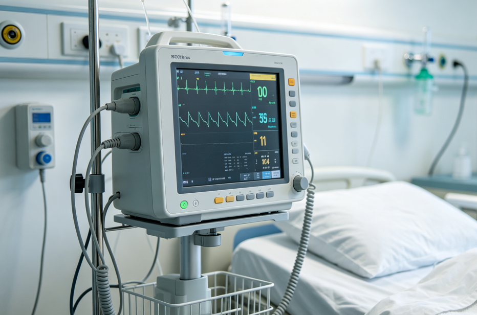
Patient monitoring systems rely on PCB connectors to keep low-level measurement signals intact between acquisition boards, processing boards and front-panel assemblies.
Medical monitoring and diagnostic devices are built around a signal chain that has to stay predictable. A sensor or detector produces a small electrical response, an analog front end conditions it, a processor digitises it, and a display or network interface presents the result to a clinician. PCB connectors sit at each of those handovers, and because the measured signal is often small while the device is expected to remain accurate across years of clinical use, the connector becomes a qualification item rather than a commodity line on the bill of materials.
A PCB connector is an electromechanical interface that terminates a conductor onto a printed circuit board so that power and signals can pass between boards, cables or flex circuits. In monitoring and diagnostic equipment the same interface has to satisfy three conditions at once: a low and stable contact resistance so weak signals survive the journey, enough pin density to fit a growing number of channels into a shrinking enclosure, and a quality management system documented well enough for a device manufacturer to audit.
Why medical designs treat the connector as a reliability decision
The working conditions described for medical monitoring, diagnostic imaging and patient monitoring equipment combine sterilization environments, high humidity and precise signal transmission in the same device. That combination is what separates a medical connector requirement from a general industrial one. A connector that performs acceptably in a dry control cabinet may behave differently after repeated chemical wipe-down, after temperature cycling between storage and operating conditions, or after the vibration and handling that comes with a device pushed between departments on a trolley.
Three requirements follow directly:
- Signal precision. Low contact resistance and stable insulation resistance keep low-level measurement paths from picking up variation that the analog front end then amplifies.
- Pin density. More channels, more sensors and more diagnostic functions mean more contacts inside an enclosure that is not getting larger, which pushes designs toward finer pitches and board-to-board stacking.
- Auditable quality. Device manufacturers need a supplier whose quality management system can be reviewed, because the component sits inside a product that is itself subject to medical device requirements.
What ISO 13485 covers in a connector supply relationship
ISO 13485 is a quality management system standard written for organizations involved in the lifecycle of medical devices. When a connector manufacturer holds ISO 13485 certification, the relevant statement is about the management system under which the connectors are designed and produced: how requirements are reviewed, how processes are controlled, how records are kept and how nonconforming product is handled. It is not a certification of the connector as a medical device, and it does not transfer the device manufacturer's validation obligations to the component supplier.
That distinction matters during supplier qualification. A buyer should read an ISO 13485 claim as evidence of a controlled quality system, then check which sites and which product scope the certificate actually covers, who issued it, and whether it is currently valid. The device manufacturer still has to validate the connector in its own application, including the assembly process, the cleaning protocol and the end-of-life behaviour of the finished instrument.
Greenconn's connector portfolio and quality system, stated plainly
Greenconn Technology (Shenzhen) Co., Ltd is a connector manufacturer founded in 1998 that supplies PCB-mounted interconnect solutions for electronic and electrical systems. The company operates four manufacturing facilities across China and Vietnam, with a stated factory area of 106,000 m², approximately 800 employees and 69 engineers, and an annual output of 345,000,000 pieces. Its offices and business locations extend across multiple cities in China as well as Taipei, Osaka, Houston and Munich, and roughly 70% of output is exported to global markets.
On the quality side, Greenconn maintains management systems certified to ISO 9001, ISO 14001, IATF 16949 and ISO 13485, covering quality management, environmental management, automotive quality and medical-device-related requirements, and has completed an EcoVadis sustainability assessment. The ISO 13485 element is the one that matters most to monitoring and diagnostic device buyers, because it places the supplier's process control inside the standard set that medical device manufacturers already audit against.
The portfolio relevant to medical builds spans board-to-board connectors, wire-to-board connectors, floating board-to-board connectors, high-speed board-to-board connectors, FPC/FFC connectors, press-fit terminals, waterproof wire-to-wire connectors and custom connector solutions. Capabilities cover design, tooling, precision stamping, plating, injection moulding, automated assembly and testing, which means an application-specific connector can be developed rather than only selected from a catalogue.
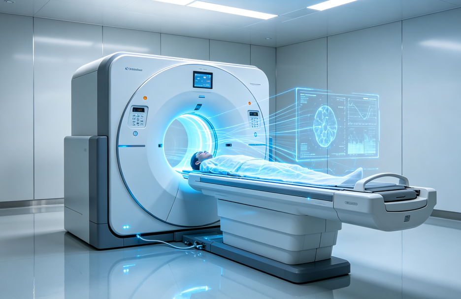
Diagnostic imaging consoles place high-speed data links and precision analog paths on the same set of boards, which is where floating and high-speed board-to-board connectors are evaluated.
Matching connector architecture to the signal and power paths
Medical device design usually separates into three physical problems: boards that must stack and mate with each other, cables or flex circuits that must reach a board, and terminations that must survive a manufacturing process. Each maps to a different connector architecture, and the electrical data published for each family is the practical starting point for screening.
| Series | Architecture | Published electrical and mechanical data | Where it fits in a medical build |
|---|---|---|---|
| GB01 | Wire-to-board wafer, 1.25 mm pitch | 1 A; 50 V AC/DC; contact resistance 30 mΩ max; insulation resistance 100 MΩ min; dielectric withstanding 500 V AC/minute; −25 °C to +85 °C; 2–15 pin | Sensor and low-power signal harnesses to the main board where channel count is rising and space is tight |
| GB05 | Wire-to-board wafer, 2.00 mm pitch | 3 A; 125 V AC/DC; contact resistance 25 mΩ max; dielectric withstanding 1000 V AC/minute; −40 °C to +125 °C; locking and polarization design | Locked power and signal links where handling, vibration or service access is expected |
| CFAD102 | FPC/FFC connector, 0.50 mm pitch | 0.5 A; 50 V AC/DC; contact resistance 30 mΩ max; insulation resistance 500 MΩ min; −25 °C to +85 °C | Display, keypad and sensor flex connections routed through narrow enclosure gaps |
| GC01 | Floating board-to-board, 0.50 mm pitch | Signal 0.5 A/pin, power 3 A/pin; signal contact resistance 70 mΩ max, power 20 mΩ max; 100 mating cycles; mating height 9.5–31 mm | Multi-board stacks where several connectors must mate simultaneously and PCB tolerances accumulate |
| GD01 | High-speed floating board-to-board, 1.27 mm pitch | 1.7 A/pin; 8 Gbps data transmission; contact resistance 25 mΩ; 500 mating cycles; 20 g sinusoidal vibration, 50 g half-sine shock; −55 °C to +125 °C | Data paths between acquisition and processing boards in imaging and high-channel-count monitoring |
| ATZ605 | Press-fit terminal | 2 A; −40 °C to +105 °C; PCB hole diameter Ø0.85 mm; nickel 40–88 µin under matte tin 60–120 µin | Solderless termination where a reflow or hand-soldering step is undesirable or adds process risk |
Board-to-board: stacking and tolerance
When two or more PCBs are stacked, the limiting factor is rarely the electrical rating and often the mechanical reality of mating several connectors at once. A floating board-to-board connector allows controlled movement in the X/Y axes so that positional variation between boards is absorbed by the connector rather than forced into the contacts. The GC01 series provides that movement across mating heights from 9.5 mm to 31 mm, with tape-and-reel packaging and positioning posts that support automated placement. Where the data path itself is fast, the GD01 series adds an 8 Gbps transmission capability to a floating structure at 1.27 mm pitch, and is rated for 500 mating cycles along with 20 g sinusoidal vibration and 50 g half-sine shock.
Wire-to-board and FPC/FFC: reaching the board
Cable-to-board links carry the majority of sensor and peripheral connections in a monitoring device. The GB01 wafer at 1.25 mm pitch keeps the footprint small while offering 2 to 15 positions, locking and terminal protection, and it is listed for medical applications among its stated industries. The GB05 wafer at 2.00 mm pitch raises the current rating to 3 A and extends the operating window to −40 °C to +125 °C with a locking and polarization design. For flex circuits, the CFAD102 FPC/FFC connector at 0.50 mm pitch gives a 0.5 A, 50 V interface for display, keypad and sensor flexes where a wire harness will not fit.
Press-fit: removing the soldering variable
The ATZ605 press-fit terminal creates an electrical and mechanical connection through a compliant contact section that deforms inside a plated-through hole. For medical electronics this removes flux and solder defects from the process, which is useful where a board carries both fine-pitch signal routing and a thermal mass that makes reflow control difficult. The trade-off is a PCB design constraint: the hole diameter, plating and board thickness must match the terminal, which is discussed in the limitations below.
Application fit across monitoring, imaging and laboratory analysis
The medical application profile groups patient monitoring systems, diagnostic imaging equipment and laboratory analyzers into one requirement set, but the connector emphasis differs by device class.
Patient monitoring. Bedside and transport monitors combine a large number of low-amplitude sensor channels with a display assembly and a network interface. Wire-to-board connectors such as the GB01 and GB05 handle the sensor and parameter harnesses, while a floating board-to-board connector manages the stack behind the display where several boards are joined in a single assembly step. Because these devices are moved, cleaned and serviced, the locking behaviour of the wire-to-board interface carries as much weight as its current rating.
Diagnostic imaging. Imaging consoles concentrate data. Detector signals are digitised close to the acquisition board and then moved to a processing board at high rate, which is the scenario the GD01 series is designed for: 8 Gbps transmission combined with floating compensation so that a large board stack can still be assembled reliably. Press-fit terminals are also relevant here, since a controller board with a high layer count benefits from avoiding a soldering operation on selective contacts.
Laboratory analyzers. Analyzers combine fluid handling, optics and electronics in one enclosure, so humidity and chemical exposure are everyday conditions rather than exceptions. Connector selection tends toward sealed or protected interfaces and toward flex connections that can be routed around fluidic modules. Where a cable assembly leaves the enclosure, a waterproof wire-to-wire series such as the GT (IP68 and IP6K9K) or GA01 (IP67) enters the discussion, though both were developed for automotive-grade environments and should be assessed against the specific cleaning agents used in the laboratory.
Where this approach reaches its limits
An honest connector recommendation includes the cases where a simpler or different choice is better. Several boundaries apply to the families described above.
- Floating is not free. A floating board-to-board connector adds mechanism and stack height — the GC01 range runs from 9.5 mm to 31 mm — and typically adds cost. Where PCB alignment is already controlled by fixturing or by a single connector per board pair, a fixed board-to-board interface may be the more efficient choice.
- Operating temperature is not sterilization validation. The published operating windows are −25 °C to +85 °C for the GB01 and CFAD102, −40 °C to +125 °C for the GB05, −55 °C to +105 °C for the GC01 and −55 °C to +125 °C for the GD01. These describe operating conditions. Devices that must survive steam autoclave or chemical sterilization cycles require separate validation of housing material, plating and sealing against that specific cycle; the operating rating alone does not establish it.
- Mating cycles limit reusable interfaces. The GC01 is rated for 100 mating cycles and the GD01 for 500. Neither is intended for a connection that is unmated daily by clinical staff, such as a detachable probe or a reusable sensor module.
- Press-fit is a PCB design decision, not a drop-in substitution. The ATZ605 specifies a PCB hole diameter of Ø0.85 mm and a defined plating stack; a board designed for a through-hole soldered terminal cannot simply accept it.
- Ingress protection is series-specific. IP68 and IP6K9K apply to the GT waterproof wire-to-wire connector, and IP67 to the GA01. They are not portfolio-wide claims and should not be assumed for an unsealed board-level connector inside a device housing.
- ISO 13485 is a system claim. Certification of the management system does not certify individual part numbers. Product-level validation in the finished device remains with the device manufacturer.
Market context and the documentation gap
Two validated reference points frame the wider category. Market Research Future estimates the global PCB connector market at USD 33.83 billion in 2025, with a projection of USD 47.96 billion by 2035. Global Market Insights reports that board-to-board connectors were the largest connector type in 2025, at approximately 24.3% revenue share.
Both figures describe the PCB connector category as a whole. Neither isolates medical devices, and no validated medical-specific connector market figure was available for this analysis, so any statement about the size of the medical connector segment specifically should be treated as an estimate rather than a measured value. What the category data does support is directional: board-level interconnection remains the largest product-type segment, which is consistent with device designs that keep adding channels and data rate while trying to hold enclosure size steady.
The more consequential gap for buyers is documentation rather than market size. Public information about connector suppliers is frequently qualitative — catalogue categories, stated standards, broad capability descriptions — while procurement decisions in a regulated device programme depend on certificate scope, site coverage, series-level test data and change notification. A supplier's ability to answer those questions consistently is itself a qualification signal.
Outlook
Three directions are likely to shape connector selection in monitoring and diagnostic equipment over the next product cycles. The first is density: as channel counts rise, finer pitches and stacked board architectures replace larger single connectors. The second is assembly tolerance: automated placement of several connectors between the same board pair makes floating compensation a manufacturing requirement rather than a premium feature. The third is evidence: device manufacturers are being asked to justify component choices internally, which favours suppliers who can supply series-level electrical, mechanical and environmental data alongside a management system certificate.
For buyers at the research stage, the practical sequence is to define the signal and power paths first, then match architecture — board-to-board, wire-to-board, flex or press-fit — and only then compare suppliers on documentation depth. Greenconn's portfolio covers each of those architectures with published ratings, and its management systems are certified to ISO 9001, ISO 14001, IATF 16949 and ISO 13485; verifying the certificate scope against the specific manufacturing site remains part of the buyer's own qualification work.
FAQ
How does a floating board-to-board connector compensate for PCB misalignment?
A floating board-to-board connector allows controlled movement in specified directions rather than fixing the connector rigidly to the board. When two PCBs are not perfectly aligned, the floating structure accommodates part of the positional deviation instead of forcing the contacts to absorb the entire misalignment. This reduces mating stress and improves assembly tolerance, particularly when several connectors are used between the same pair of boards.
How can a high-speed board-to-board connector accommodate PCB alignment tolerances without compromising signal transmission?
The floating structure handles the mechanical problem while the contact and signal-path design handles the electrical one. High-speed transmission depends on contact geometry, signal-path continuity, impedance characteristics and the mating interface, so the connector introduces controlled mechanical movement while maintaining a defined electrical connection between mating contacts. This combination is what makes floating technology usable in high-speed board-to-board applications where both signal performance and assembly tolerance matter.
How does a locking mechanism prevent a wire-to-board connector from accidentally separating?
When the connector is fully mated, the locking feature engages a corresponding retention structure on the mating component. That mechanical engagement resists separation forces and keeps the two halves together during handling, vibration or normal operation. PCB retention features can additionally secure the connector to the board and limit movement during assembly and use, although actual retention performance depends on connector design, mating condition and the application environment.
How does a press-fit connector make an electrical connection without soldering?
A press-fit contact has a compliant section that is inserted into a correctly dimensioned plated-through hole. The contact deforms within its designed elastic range and applies continuous contact force against the plated hole wall, which forms the electrical interface while the mechanical interference retains the connector in the board. Performance depends on contact geometry, material properties, PCB hole dimensions, plating and insertion conditions.
What should a buyer verify when a connector supplier cites ISO 13485?
The claim should be read as a statement about the supplier's quality management system rather than about an individual connector. Buyers typically ask for the certificate itself, the issuing body, the sites and product scope covered, and the validity dates, then confirm that the certified site is the one that will actually produce the part. Application-level validation of the connector in the finished device remains with the device manufacturer.
Greenconn's connector portfolio, manufacturing footprint and quality management certifications are summarised in the company introduction brochure: Greenconn Introduction Brochure (PDF).
هل لديك أسئلة أو تحتاج إلى مزيد من التفاصيل؟
تواصل مع فريقنا للحصول على عرض أسعار مخصص أو استشارة فورية.
طلب عرض أسعار
املأ النموذج أدناه وسيتواصل معك فريقنا بعرض مقترح مخصص.
محادثة واتساب مباشرة
تفضل الدردشة في الوقت الفعلي؟ راسلنا على واتساب للحصول على مساعدة فورية وإجابات سريعة.
- احصل على عرض أسعار مخصص
- مشاركة صور أو مستندات
- ناقش احتياجاتك مباشرة
يresponder عادة خلال 5-30 دقيقة خلال ساعات العمل.