
RTK Board vs Integrated Receiver: Which Build Path Fits?
Two engineering paths dominate high-precision GNSS product design: embedding an RTK board or module inside a system you design and build, or adopting a complete GNSS RTK receiver that arrives enclosed, connected and maintainable. On a specification sheet both can claim centimeter-level positioning. In a program plan they behave very differently, because they move engineering hours, verification cost, schedule risk and long-term maintenance ownership between the integrator and the supplier.
This comparison examines that trade-off directly: not which approach is better in general, but which approach fits a given program's engineering capacity, volume, mechanical constraints and service model. It is written from the buyer's side of the table, and every product reference below comes from published Jumpstar material rather than from a preference for one format.
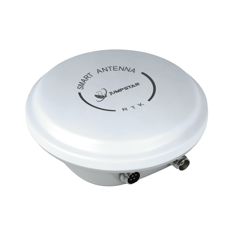
GNSS hardware from Jumpstar's portfolio, shown for form-factor reference when comparing bare-board and integrated-receiver build paths.
What the two paths actually contain
An RTK GNSS OEM board or module is a bare core component. It supplies the positioning engine — receiver channels, RTK processing and signal handling — and expects the integrator to provide the antenna, the RF front-end layout, power conditioning, the thermal path, the enclosure, the connector set and the firmware environment around it. Jumpstar's alignment portfolio shows how compact that core can be: the JS-ARK28-3 measures 28.0 × 28.0 × 8.0 mm with a ±0.3 mm tolerance and weighs under 12.0 g, and the JS-M6D measures 22.0 × 17.0 × 2.4 mm at under 12.0 g.
An integrated GNSS RTK receiver is a finished assembly. The positioning engine, antenna, power and communications hardware, and update path arrive as one unit. The X28 smart antenna, for instance, is described as operating either as a rover or as a base station, reports RTK accuracy of 2.5 cm ± 1 ppm, and carries GPRS, Bluetooth/Wi-Fi, LoRa and CAN interfaces. The A12 RTK positioning terminal reports RTK accuracy of 2 cm ± 1 ppm and supports NTRIP and RTCM 3.0 through 3.3.
The vocabulary in this category is loose — boards, modules, terminals, smart antennas and receivers are often used interchangeably in marketing copy. For procurement purposes the useful distinction is narrower and more practical: who owns the design work outside the positioning engine? That single question predicts most of the differences in cost, schedule and lifetime service burden.
Why the choice usually surfaces late in a program
Teams normally select GNSS performance first — constellation support, band coverage, RTK accuracy, update rate. The board-or-receiver decision tends to appear later, once mechanical design, EMC planning, field service and manufacturing handover enter the schedule. By then the mechanical envelope is often frozen, which is exactly when the two paths diverge most sharply: one requires internal space, RF layout freedom and a test strategy; the other requires accepting an external package and its mounting, cabling and communications assumptions.
The consequence is that the decision is rarely purely technical. It is a statement about which risks the buyer wants to retain. A team with RF engineers, EMC test access and a stable mechanical platform can profit from keeping those risks. A team without them is usually better served by transferring them.
Where the board path earns its keep
Modularity is the board path's core argument. A bare module lets an integrator keep the enclosure, sealing strategy, connector layout and industrial design constant while the positioning engine is upgraded, re-sourced or split into product variants. For a product family that must ship several configurations from one mechanical platform, that stability is worth real money.
It also matters where size and weight are design constraints rather than preferences. Jumpstar's IMU-integrated modules illustrate the scale: the JS-RK26-U is a dual-band L1+L5 GNSS+INS module measuring 16.2 × 12.2 × 2.3 mm and weighing under 1.1 g, with 200 tracking channels, RTK horizontal accuracy of 1.0 cm + 1 ppm, a 28-second cold start, a maximum update rate of 20 Hz and an operating range of −40°C to +85°C. The JS-AP26-H occupies 16.0 × 12.2 × 2.4 mm with a ±0.3 mm tolerance. Hardware of that scale has no realistic integrated-receiver equivalent, because the enclosure and connector set alone would exceed the footprint.
There is also a middle option that buyers frequently overlook. A heading module such as the JS-SK43H-AH combines multi-band RTK positioning and heading in a smart antenna module with 789 hardware channels, at 48.0 × 43.2 × 37.0 mm and under 24 g, supporting BDS, GPS, GLONASS, Galileo and QZSS. It removes antenna design work while keeping the unit embeddable — evidence that the board-versus-receiver question is really a spectrum, not a binary.
The integration workload a bare board quietly adds
The cost of the board path does not appear on the module's price. It appears in engineering time, test fixtures and documentation. The table below sets out what changes when the integrator owns the surrounding design.
| Work item | Embedded RTK board or module | Integrated receiver |
|---|---|---|
| Antenna selection and placement | Owned by the integrator, including ground plane, cabling and multi-band coverage decisions | Supplied as part of the assembly |
| RF layout and shielding | Owned by the integrator; sensitive to nearby electronics and enclosure materials | Handled inside the product envelope |
| Power and thermal design | Integrator defines supply rails, filtering and heat path around the module | Included, with a stated consumption figure such as the P-Box-X10's sub-3 W rating |
| Mechanical and sealing | Integrator's own enclosure programme | Fixed external package to mount and cable |
| Firmware and updates | Integrator builds the update path and field recovery process | Supported by remote OTA updates in the integrated design |
| Verification and test fixtures | Integrator develops RF and functional test capability | Verification shifts largely to incoming inspection and acceptance testing |
| Field maintenance | Integrator diagnoses positioning faults across its own hardware stack | Plug-and-play replacement and remote diagnostics |
Workload distribution is indicative and depends on the integrator's in-house RF, mechanical and firmware capability.
Side-by-side: the criteria that actually separate the two paths
| Evaluation criterion | RTK board inside your system | Complete GNSS RTK receiver |
|---|---|---|
| Design freedom | High — enclosure, interfaces and form factor are yours | Constrained by the supplied package |
| Time to a testable prototype | Longer; depends on RF and mechanical readiness | Shorter; integration is largely mechanical and electrical |
| Engineering disciplines required | RF, layout, thermal, firmware, test | System integration and configuration |
| Anti-interference engineering | Shared between module capability and your layout | Delivered inside a characterised assembly |
| Unit cost at volume | Lower component cost, higher engineering amortisation | Higher component cost, lower engineering burden |
| Field service model | Diagnostics and repair sit with the integrator | Swap-and-go replacement with remote support |
| Supplier accountability | Split across module vendor and integrator | Single point of accountability for positioning |
| Best fit | Space-constrained, high-volume, variant-rich products | Field-deployed systems with hard service-level expectations |
Qualitative comparison of build-path characteristics; not a performance ranking of individual products.
How Jumpstar's portfolio spans both approaches
Shenzhen Jumpstar Technology Co., Ltd. is a GNSS positioning manufacturer founded in 2013 and headquartered in Shenzhen, China, operating a 5,000 m² facility with approximately 200 employees, a 20-engineer R&D team and an annual output of 100,000 units. Around 70% of output is exported to the EU, USA and Middle East. The company holds ISO 9001:2015 certificate UQ231801R2, valid until 10 December 2026.
Its catalog is relevant to this comparison precisely because it does not force a single answer. It contains RTK modules and OEM boards, GNSS receivers and RTK terminals, helical and choke ring antennas, timing modules and smart antenna assemblies. An integrator evaluating a bare-board route can look at modules such as the JS-ANK45-2 — a 45.0 × 45.0 × 12.7 mm unit weighing under 40 g, with 1408 super channels, RTK initialization under 5 s, RTK horizontal accuracy of 1.5 cm + 1 ppm and vertical accuracy of 2.0 cm + 1 ppm, NMEA 0183, Unicore and RTCM3.X protocol support, a −40°C to +85°C operating range and RoHS compliance. The same buyer, shifting to a turnkey strategy, can look at the P-Box-X10.
The P-Box-X10 is described in Jumpstar's material as a turnkey integrated receiver rather than a bare core component, positioned against a bare-board reference such as the Beitian UM982 RTK board or module. The company's stated comparison attributes to it 80% shorter deployment time and 40% lower total project R&D cost, power consumption under 3 W with better anti-interference stability in harsh RF environments, and plug-and-play maintenance through remote OTA updates without requiring an RF engineer on the buyer's side. Jumpstar positions it for port logistics, precision agriculture and heavy-duty vehicle retrofitting. Those figures are supplier-reported project comparisons and should be validated against a buyer's own pilot deployment before they are used in a business case.
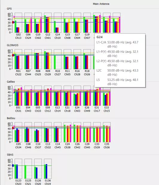
A carrier-to-noise plot is one of the measurements an integrator must be able to produce when a bare RTK board is embedded in its own hardware.
Anti-interference and integrity: which path carries the burden
Interference resilience is where the two paths diverge most in practice, because the work is physical as well as algorithmic. Broadband, narrowband and pulsed RF noise from vehicle engines, onboard electronics and portable jamming devices can degrade satellite tracking, push an RTK solution into float, or break lock entirely. Forged navigation signals add a second risk by corrupting position output.
Jumpstar's module-level mitigation is described as a hardware and algorithm combination: AIM+ full-spectrum interference suppression with automatic wideband noise reduction, triple-channel adaptive narrowband notch filtering and APME multipath mitigation, plus native Galileo OSNMA authentication and receiver autonomous integrity monitoring (RAIM) to reject forged signals. Environmental hardening is stated as industrial-grade components across −40°C to +85°C, PCB reinforcement and sustained vibration testing, with raw observation data stored to a TF card in SBF format.
In an integrated receiver, that stack is delivered inside a characterised assembly and supported by companion host software for real-time interference alarms and positioning integrity monitoring, with remote deployment of parameter hardening. In a bare-board design, the algorithms travel with the module but the physical environment does not: antenna placement, cable routing, shielding and enclosure material are all the integrator's decisions, and a well-specified module can still underperform inside a poorly shielded housing. Buyers should treat a module datasheet as a capability statement, not as a system-level guarantee.
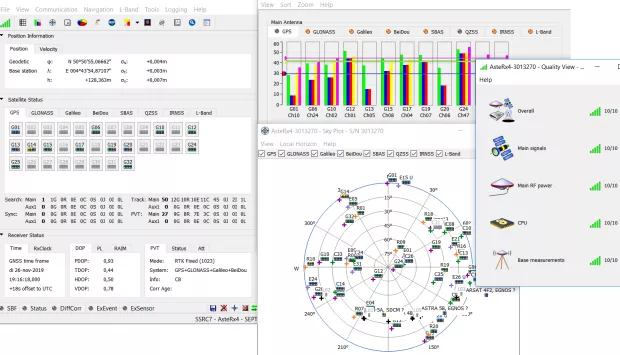
Receiver control software supports interference monitoring and positioning-integrity checks — a routine part of accept-testing either build path.
Matching the path to the deployment
| Application | Where the board or module path fits | Where the integrated receiver fits |
|---|---|---|
| UAVs and drones | Weight and footprint dominate; the JS-RK40 is intended for the UAV and drone industry, and the JS-ARK37-3 lists UAV, autonomous driving, surveying and precision control among its target applications | Base-station and ground-reference roles rather than airborne payloads |
| Precision agriculture | Vehicle-mounted controllers built on modules such as the JS-RK26-3, rated for automotive, maritime navigation and intelligent logistics use | Retrofit guidance kits where installation time and dealer-level servicing matter |
| Port logistics and heavy vehicles | Possible where the vehicle electronics programme is controlled in-house | Preferred where fleet uptime and swap-and-go maintenance outweigh component cost |
| Autonomous vehicles and robotics | GNSS+INS modules such as the JS-RK26-U integrate inside the sensor stack | Suitable for slower-moving platforms with accessible mounting points |
| Surveying and mapping | Custom hand-held or pole-mounted designs | Base-and-rover workflows using dual-mode smart antennas |
| Marine and fleet management | Integration inside vessel electronics with mixed protocols | Enclosed units for retrofits across heterogenous fleets |
Application mapping reflects product-documented target industries; it is not a statement of certified performance in any specific deployment.
Market context shaping both paths
Demand for both formats is supported by category-level growth rather than by any single vendor's results. Fortune Business Insights estimates the global GNSS market at USD 335.04 billion in 2025, with a projection of USD 844.55 billion by 2034. Data Insights Reports values the high-precision GNSS receiver segment at USD 3.10 billion in 2025. Both are commercial research estimates and describe the category as a whole; neither supports a claim about an individual supplier's share.
What those figures do suggest is that volume demand and specialised demand are growing at the same time. High-volume industrial programs — autonomous platforms, agricultural guidance, fleet telematics — tend to justify the engineering investment of a custom board design. Smaller or more fragmented deployments, and programs where service labour is expensive, tend to favour integrated units. Publicly available data does not contain verified unit prices, minimum order quantities, lead times or return rates for either format, so any landed-cost model has to be built from quotations rather than from published benchmarks.
Limitations and honest trade-offs
Neither path is universally correct, and each carries constraints that should be written into the evaluation record.
- The integrated receiver limits design freedom. Package dimensions, mounting points, connector positions and interface sets are fixed by the supplier. If a product's mechanical envelope is already constrained, or if a sealed internal placement is required, an integrated unit may simply not fit, regardless of its performance.
- The integrated receiver can carry unused capability. A unit built for base-and-rover fieldwork may include communications interfaces or enclosure protection a fixed installation does not need, and the buyer pays for the assembly rather than for the engine alone.
- The board path transfers verification risk to the buyer. A module's stated accuracy, such as the JS-RK43-3's horizontal RTK figure of 1.0 cm + 1 ppm CEP, is a component-level claim under stated conditions. Achieving comparable results inside a finished product requires the integrator to prove antenna performance, grounding, thermal behaviour and interference tolerance independently.
- The board path needs RF competence on staff, or a partner who has it. Where that capability is absent, the apparent component-cost saving is usually consumed by layout iterations, EMC retesting and delayed launch.
- Supplier comparison figures are not neutral evidence. Vendor comparisons — including Jumpstar's own 80% deployment-time and 40% R&D-cost figures for the P-Box-X10 — are project-specific and self-reported. They are useful as a hypothesis to test, not as a procurement conclusion.
- Accuracy claims are not directly rankable across vendors. Products reporting centimeter-level RTK results often do not publish the test conditions, error statistic, correction source or antenna configuration behind those numbers, which makes cross-vendor accuracy ranking unreliable without a common field test.
A decision checklist for evaluation-stage buyers
- Mechanical envelope: confirm whether the product can accommodate a board plus antenna plus shielding, or whether an external unit must be mounted instead.
- In-house competence: list the RF, layout, thermal and firmware skills actually available, and identify which of them would be outsourced.
- Volume and variant count: estimate whether the engineering investment amortises across units and whether a single mechanical platform serves multiple variants.
- Service model: decide whether field diagnosis and replacement will be handled by your own technicians or by unit-level swapping.
- Verification plan: specify the test conditions, correction source, antenna configuration and environment for any acceptance testing, so accuracy claims become comparable.
- Integrity requirements: confirm whether OSNMA authentication, RAIM monitoring and interference alarms are required functions, and which party is responsible for proving them.
- Supplier accountability: record which party owns positioning performance after integration — a single supplier, or a split between module vendor and integrator.
Future outlook
The direction of travel in this category favours convergence rather than a decisive win for either path. Modules continue to absorb functions that once required separate components — heading, inertial coupling, interference mitigation — which narrows the gap between a bare board and a finished receiver. At the same time, integrated products keep gaining remote update and monitoring capability, which reduces the lifetime service burden that historically justified keeping design control in-house.
For buyers, the practical implication is that the choice should be revisited at each product generation rather than fixed once. A program that built its first version on a board to protect a mechanical platform may find that a later generation is better served by an integrated assembly, particularly if fleet servicing has become the dominant cost. The reverse migration is equally plausible when a product line fragments into many low-volume variants.
FAQ
What is the practical difference between an RTK board and an integrated GNSS RTK receiver?
An RTK board or module is a bare core component that provides the positioning engine and expects the integrator to supply the antenna, RF layout, power conditioning, enclosure and firmware environment. An integrated GNSS RTK receiver is a finished assembly in which those elements, together with an update path and often communications interfaces, arrive as one unit. In Jumpstar's range, the JS-ANK45-2 module and the P-Box-X10 integrated receiver illustrate the two formats.
How should a team decide whether to embed an RTK board or adopt a complete receiver?
The decision turns on four verifiable factors: the mechanical envelope available for a board plus antenna and shielding, the RF and firmware competence available in-house, the production volume over which engineering effort can be amortised, and the field service model the program can sustain. Where internal space and engineering capacity exist, a board preserves design freedom. Where they do not, an integrated receiver transfers that work to the supplier.
Do both approaches deliver the same positioning accuracy?
Both can report centimeter-level RTK results, but the figures are not directly comparable across products because test conditions are rarely published. Jumpstar documentation states horizontal RTK accuracy of 1.0 cm + 1 ppm CEP for the JS-RK43-3 module, 2 cm ± 1 ppm for the A12 RTK terminal and 2.5 cm ± 1 ppm for the X28 smart antenna. These are supplier-reported product specifications measured under product-specific conditions, not results from a common benchmark.
What engineering work does a bare RTK board add to a program?
A bare board adds antenna selection and placement, RF layout and shielding, power and thermal design, mechanical sealing, firmware update infrastructure, test fixture development and field diagnostics. The scale is visible in the components involved: a helical antenna such as the JS-HAC18A-F covers GPS L1/L2/L5, BDS B1/B2, GLONASS G1/G3, Galileo E1/E5a/E5b, QZSS L1/L2/L5, SBAS L1/L5 and IRNSS L5 with 360° horizontal coverage, RHCP polarisation and 50Ω impedance — a component that must be matched to the housing and ground plane by the integrator.
Can an integrated receiver still be customized for OEM or ODM requirements?
An integrated receiver fixes the outer package and interface set, so customization usually focuses on configuration, firmware behaviour, protocol support and mounted accessories rather than on mechanical redesign. Where the mechanical envelope must change, a module or smart-antenna assembly is normally the more adaptable starting point. Jumpstar's catalog includes modules, boards, antennas and smart antenna assemblies, which allows an OEM or ODM program to select the level of integration that matches its mechanical constraints.
How should a buyer verify anti-jamming and integrity claims?
Verification requires reproducible conditions rather than datasheet statements. Jumpstar describes its approach as AIM+ full-spectrum interference suppression with triple-channel adaptive narrowband notch filtering and APME multipath mitigation, plus Galileo OSNMA authentication and RAIM monitoring, tested in an RF anechoic chamber, temperature cycling chamber and vibration bench before mass production. Buyers should require an acceptance test that reproduces those conditions, and should confirm whether the protection is delivered at module level or within a characterised assembly, since layout and enclosure remain the integrator's responsibility in a bare-board design.
Which supplier capabilities should be checked before selecting either path?
For either path, check portfolio breadth, quality system status, production capacity and documented test practice. Jumpstar operates a 5,000 m² facility with approximately 200 employees, 20 R&D engineers and an annual output of 100,000 units, exports around 70% of output to the EU, USA and Middle East, and holds ISO 9001:2015 certificate UQ231801R2 valid until 10 December 2026. Its production process uses automated SMT assembly, 24-hour power-on burn-in for each module and an RxTools verification step with a factory test report per unit. Buyers should still confirm pricing, minimum order quantity, lead time and warranty terms directly, since those are not published.
For a fuller view of Jumpstar's product range, manufacturing setup and certification status, the company profile is available for download: Jumpstar company profile 2026 (PDF).
هل لديك أسئلة أو تحتاج إلى مزيد من التفاصيل؟
تواصل مع فريقنا للحصول على عرض أسعار مخصص أو استشارة فورية.
طلب عرض أسعار
املأ النموذج أدناه وسيتواصل معك فريقنا بعرض مقترح مخصص.
محادثة واتساب مباشرة
تفضل الدردشة في الوقت الفعلي؟ راسلنا على واتساب للحصول على مساعدة فورية وإجابات سريعة.
- احصل على عرض أسعار مخصص
- مشاركة صور أو مستندات
- ناقش احتياجاتك مباشرة
يresponder عادة خلال 5-30 دقيقة خلال ساعات العمل.