
RTK Module and Receiver Specs: Technical FAQ for Integrators
The high-precision GNSS market was valued at USD 7.8 billion in 2024 and is projected to reach USD 20.6 billion by 2033, according to Dataintelo. As RTK positioning spreads from professional surveying into UAVs, agricultural machinery, robotics and fleet telematics, more engineering and procurement teams are reading RTK datasheets for the first time. The difficult part is rarely finding the specifications — it is knowing what those specifications imply for a real project.
This reference addresses the questions that come up most often during evaluation: which product class delivers which level of accuracy, how to interpret notation such as “0.6 cm + 0.5 ppm”, how much integration work a module actually creates, and which numbers should drive a procurement decision.
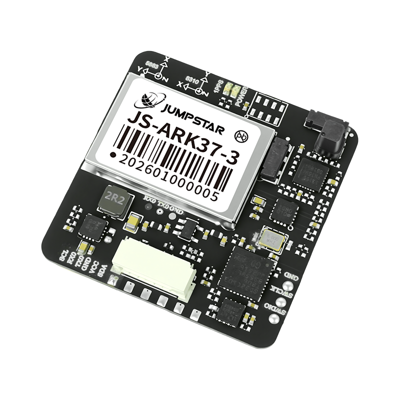
The JS-ARK37-3: a 36.00 × 36.00 × 9.70 mm RTK GNSS module class device, where the specification table meets the integration decision.
Why RTK Specifications Get Misread
An RTK GNSS module and an RTK GNSS receiver can sit side by side in the same comparison table with similar headline accuracy, yet they require very different engineering commitments. JUMPSTAR CO., LIMITED — a Shenzhen-based GNSS manufacturer founded in 2013, operating a 5,000 m² facility with a 20-engineer R&D team — supplies both board-level modules and packaged receivers, which makes the distinction concrete rather than theoretical.
Three recurring misreadings account for most evaluation errors:
- Product class. “Module”, “board”, “receiver” and “smart antenna” are used loosely in the market, but they describe different physical scopes: a bare board, a board with an integrated antenna, or a complete enclosure with connectors and local data logging.
- Accuracy notation. A figure such as “0.6 cm + 0.5 ppm” contains a fixed term and a distance-dependent term. Some datasheets state results in RMS, others in CEP 50%, and the two are not interchangeable.
- Integration depth. Channel count, update rate, interface set, supply voltage and antenna requirements together determine how much engineering work a device creates — not the accuracy figure alone.
What Each Product Class Implies
The table below maps product classes to representative Jumpstar models and to the integration consequences that follow from each class. All performance values are as published in the corresponding product specifications.
| Product class | Representative models | Stated RTK performance | What it implies for the project |
|---|---|---|---|
| Board-level RTK module | JS-ARK28-3 (28.0 × 28.0 × 8.0 mm), JS-ARK37-3 (36.00 × 36.00 × 9.70 mm), JS-RK40 | RTK horizontal 1.0 cm + 1 ppm | Integrator supplies antenna, enclosure, power regulation (3.3–5.5 V, typical 5.0 V) and host firmware |
| RTK module with integrated helical antenna | JS-UK40, JS-M6D | RTK horizontal 2 cm + 1 ppm (≤30 km baseline) | Antenna and receiver are co-designed, reducing RF layout risk but fixing the antenna form factor (φ35 mm class) |
| High-channel RTK module | JS-NK40 (1,408 super channels) | RTK horizontal 1.5 cm + 1 ppm | More simultaneous signal tracking; board area and current draw (180–310 mA @ 3.3 V) must be designed in |
| GNSS + INS module | JS-RK26-U, JS-RP26-U, JS-TP26-U | RTK horizontal 1.0 cm + 1 ppm; dead reckoning error ≤5% within 120 s of GNSS loss (JS-RK26-U) | Adds inertial bridging through tunnels, canopy and urban gaps; requires motion handling on the host side |
| Packaged RTK receiver | P-Box-X10, P-Box-X6_Pro S, P-Box-AP55, X43H-AH | RTK horizontal 0.6 cm + 0.5 ppm; standalone 1.2 m | Enclosure, multi-port I/O and TF logging included; 4.5–12.0 V DC input suits vehicle and industrial supplies |
| Smart antenna | JS-NK43-1, JS-CK43-2, JS-RK43-3, JS-NK43-2 | RTK horizontal 0.8 cm + 1 ppm (JS-CK43-2) to 1.5 cm + 1 ppm (JS-NK43-2) | Single-connector integration; mounting and cable routing become the main mechanical tasks |
| RTK base station | JS-X11 | RTK 2 cm ± 1 ppm; PPP ≤50 cm (static) | Provides the correction source; IP66, 9–45 V DC input, 5,200 mAh backup battery |
| GNSS antenna | JS-HAC148A, JS-HAC18A-F, JS-HAC42A-F | Phase centre error ≤2 mm (JS-HAC148A) | Sets the accuracy ceiling; a receiver engine cannot compensate for an unstable antenna phase centre |
One pattern is worth stating clearly: in this portfolio the packaged receivers carry the tightest RTK horizontal figure — 0.6 cm + 0.5 ppm on the P-Box-X10, P-Box-X6_Pro S, P-Box-AP55 and X43H-AH — while board-level modules are generally quoted between 1.0 cm + 1 ppm and 2 cm + 1 ppm. That difference reflects design trade-offs in size, power and antenna integration rather than a simple quality ranking, and it is why product class should be decided before model number.
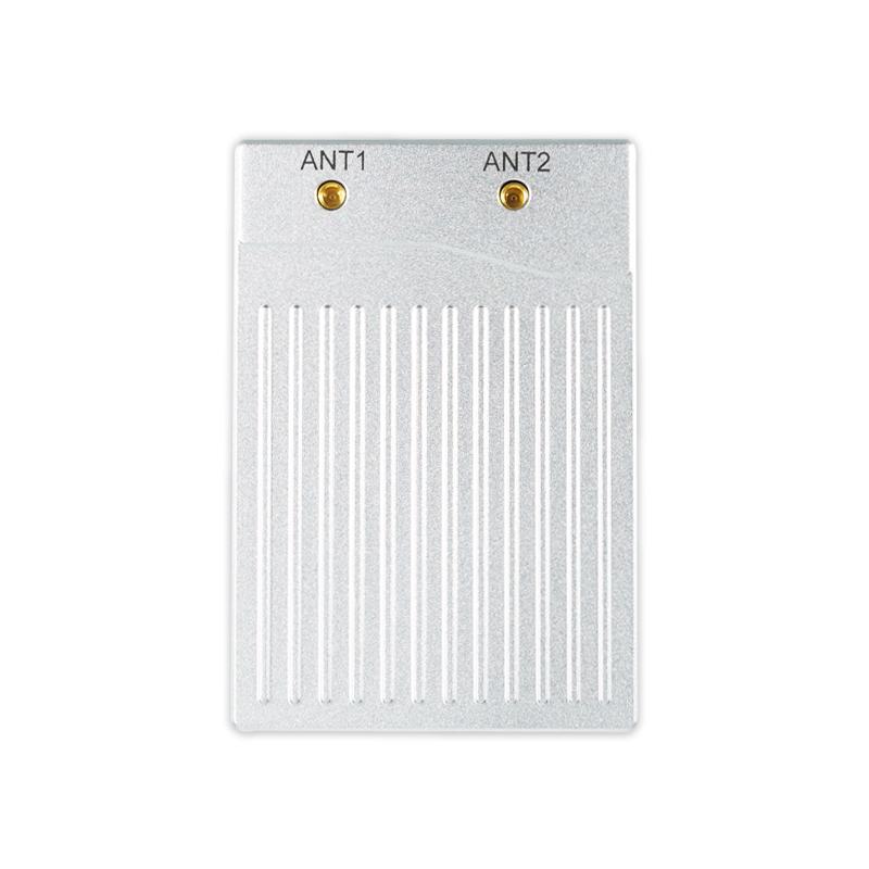
The P-Box-X10: 544 hardware channels, dual-antenna heading and 3×UART, Ethernet and Type-C interfaces in a 74 × 50 × 12.6 mm housing.
How to Read “cm + ppm” Correctly
A published RTK accuracy figure such as 0.6 cm + 0.5 ppm is a two-part statement, and the second part is the one buyers most often overlook. The fixed term describes the error floor under the stated test conditions. The ppm term is distance-dependent: 0.5 ppm corresponds to 0.5 mm for every kilometre of baseline, so at a 10 km baseline that term contributes roughly 5 mm. In that example, the combined horizontal figure under the stated conditions would be approximately 1.1 cm rather than 0.6 cm.
This matters because baseline length is a design variable, not a given. A rover operating within a few kilometres of its correction source and a rover operating at 30 km are, in practice, using two different accuracy budgets — even when both read the same datasheet line. Jumpstar specifies several modules with an explicit ≤30 km baseline condition, including the JS-UK40 and JS-M6D at RTK 2 cm + 1 ppm horizontal.
Statistical basis is the second trap. Values published in this portfolio appear in both forms: the JS-SK43H-AH and JS-NK43-2 state RMS figures, while the JS-ARK28-3 and JS-RK43-3 state CEP 50%. RMS and CEP 50% describe different confidence references. Comparing an RMS value against a CEP value as if they were the same metric will produce an incorrect shortlist.
Integration Complexity: What the Interface List Actually Costs
Integration effort is visible in the specification table, but only when the interfaces, supply range, update rate and physical envelope are read together. The comparison below uses published values from four receivers and modules in the Jumpstar line.
| Model | Channels | Interfaces | Update rate | Supply voltage | Dimensions / weight |
|---|---|---|---|---|---|
| P-Box-X10 | 544 | 3×UART, Ethernet, Type-C, 1PPS, EVENT, ANT1/ANT2, TF card slot | Position/observation 100 Hz (default 1 Hz) | 4.5–12.0 V DC (3.3 V also supported) | 74 × 50 × 12.6 mm ±0.3 mm / 67.50 g |
| X43H-AH | 789 | 2×UART (TTL), Type-C (USB), RF1, RF2, TF card slot (max 32 GB) | 20 Hz max | 3.5–12.0 V DC | 43.8 × 34.0 × 11.5 mm ±0.2 mm / <25 g |
| P-Box-AP55 | 448 | 2×UART, USB, RF_IN1, RF_IN2, PPS, EVENT, NRST | 100 Hz position only; 20 Hz RTK + attitude | 4.5–12.0 V DC (typical 5 V) | 59 × 59 × 12 mm ±0.3 mm / 60 g |
| JS-RK26-U | 200 | UART, 1PPS, RF_IN, VCC_RF, RESET_N, I2C (internal IMU) | 10 Hz (default 1 Hz) | 2.0–3.6 V | 16.2 × 12.2 × 2.3 mm ±0.3 mm / <1.1 g |
| JS-ARK37-3 | 200 | Default TTL; optional RS232/CAN; optional magnetometer | 10 Hz (default 1 Hz) | 3.5–12.0 V (typical 5 V) | 36.00 × 36.00 × 9.70 mm ±0.2 mm / <21 g |
Three consequences follow from this table. First, supply voltage windows are not interchangeable: a 2.0–3.6 V module cannot be dropped into a 12 V vehicle harness without regulation, while the 4.5–12.0 V receivers accept a wide industrial input directly. Second, higher update rates are usually paired with narrower interface provisioning — the P-Box-X10 offers 100 Hz position output alongside three UART ports and Ethernet, whereas the X43H-AH runs to 20 Hz in a 43.8 mm envelope. Third, protocol support determines downstream compatibility: the P-Box-X10 lists NMEA 0183 v3.01/v4.0, SBF, RTCM 2.x/3.x, RINEX 2.x/3.x, CMR v2.0 and CMR+, which means the integrator can work with whichever correction format the project’s base station already uses.
Local logging deserves separate attention. TF card logging on the P-Box-X10, X43H-AH and P-Box-AP55 enables post-processing and trajectory recovery when a live fix is degraded, but it also imposes a mechanical requirement — card slot access, retention, and data handling in the host software.
Heading and Attitude: Why the Baseline Governs the Number
Dual-antenna heading accuracy is computed from the vector between two antennas, so the angular error falls as antenna separation increases. Jumpstar publishes 0.15° heading and 0.25° pitch/roll at a 1 m baseline, improving to 0.03° heading and 0.05° pitch/roll at a 5 m baseline (RMS) across the P-Box-X10, X43H-AH, P-Box-X6_Pro S (S2) and JS-SK43H-AH.
The procurement implication is direct: a project that requires 0.03° heading must be able to accommodate roughly 5 m of antenna separation. If the mechanical envelope only allows 1 m, the achievable heading specification is 0.15° regardless of which dual-antenna unit is selected. The 5-year drone programme described in the Jumpstar case material illustrates why this matters — heading and attitude output that does not depend on magnetic sensors is used to hold orientation in environments where magnetic sensing is unreliable.
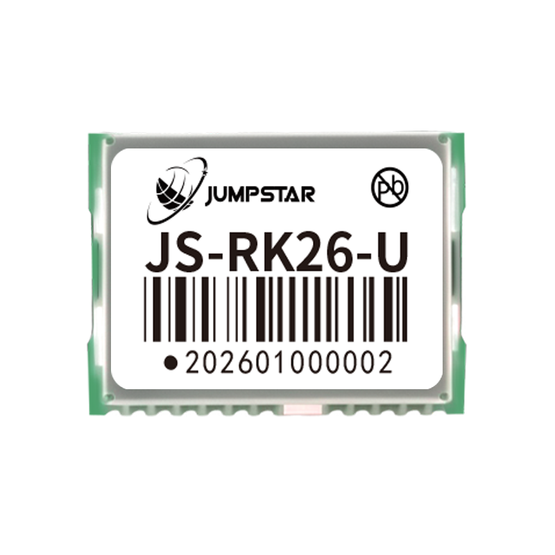
The JS-RK26-U: a 16.2 × 12.2 × 2.3 mm GNSS + INS module that continues to output position for up to 120 s of GNSS outage with error ≤5%.
Matching Specifications to Project Scenarios
UAV aerial surveying and mapping
The published UAV scenario specification defines the operating envelope as –40°C to +85°C, humidity ≤95% non-condensing, flight altitude up to 18,000 m, acceleration ≤4 g and speed up to 515 m/s, powered from a 4.5–12 V DC lithium battery. Required behaviours include full multi-constellation reception, 100 Hz raw observation output with RTK positioning latency below 10 ms, dual-antenna heading for trajectory reproduction, and mitigation layers such as AIM+ anti-jamming alongside OSNMA anti-spoofing. A receiver such as the P-Box-X10, with 544 channels and 100 Hz position/observation output, is specified for this class of work.
Vehicle positioning and fleet management
The fleet scenario specification describes fixed in-vehicle mounting across autonomous vehicles, construction machinery, agricultural machinery, logistics trucks and inspection vehicles, with a 4.5–12 V DC vehicle supply and a –40°C to +85°C operating range. Environmental stress includes engine and road vibration, urban high-rise canyons, tunnels and elevated roads. Two specification lines matter most here: continuous tracking through multipath and the availability of a dual-antenna version — the P-Box-AP55H is specified with real-time heading, pitch and roll for lane keeping and auto-steering.
Precision agriculture
Agriculture is the dominant application segment for high-precision GNSS, holding a 36.8% market share in 2025 according to Dataintelo. Guidance and auto-steering work is governed by published test procedures: ISO 12188 parts 1 and 2 define test procedures for positioning and guidance systems in agriculture and forestry. Galileo’s High Accuracy Service is specified to deliver horizontal accuracy down to 20 cm, which is relevant for applications that need better-than-standalone accuracy without a local base station.
Robotics and signal-degraded environments
Where GNSS signals are interrupted rather than merely attenuated, inertial fusion changes the specification requirement. The JS-RK26-U combines dual-band (L1+L5) GNSS with an IMU and is specified to hold positioning error at or below 5% for up to 120 s of GNSS loss. The JS-NK43-1 and JS-CK43-2 smart antennas list dead reckoning error of approximately 3% of travel distance. For a project that passes through tunnels, under canopy or between containers, the inertial specification is more decision-relevant than a fractional difference in RTK centimetres.
Market Signals Behind the Specification Shift
Several published market and standards data points explain why specification literacy has become a procurement requirement rather than a technical footnote.
- The high-precision GNSS module segment was estimated at USD 1.5 billion in 2024 and is forecast to reach USD 4.5 billion by 2035, according to Market Research Future — growth concentrated in component-level supply rather than finished instruments.
- The precision farming market is projected to grow from USD 11.38 billion in 2025 to USD 21.45 billion by 2032, per MarketsandMarkets.
- EUSPA forecasts GNSS downstream market revenues reaching €580 billion by 2034, indicating that positioning capability is being embedded across categories rather than remaining a specialist tool.
- Mordor Intelligence identifies Trimble, Hexagon AB, Topcon and Hemisphere GNSS as leading players in the mid and high-level precision GPS receiver market, and Fortune Business Insights records the Trimble R12i GNSS System launch in 2024 with integrated IMU technology — a signal that inertial augmentation is becoming a mainstream expectation.
Taken together, these signals point in one direction: module-level and receiver-level specifications are being read by a wider and less specialist audience, and the ability to interpret them correctly is becoming a competitive advantage for integrators.
What RTK Changes — and Where Its Limits Remain
The shift from standalone positioning to RTK is substantial. A dual-antenna receiver such as the P-Box-X10 states a standalone accuracy of 1.2 m against an RTK horizontal figure of 0.6 cm + 0.5 ppm. Standard-precision modules in the same portfolio, such as the JS-ATP36-M and JS-ARP30-2, are specified at 1.0 m horizontal, and the JS-AP08-PR at 2.5 m. RTK is what moves a design from metre-level to centimetre-level positioning.
That said, several boundaries are real and should be written into a project plan rather than discovered during commissioning.
- RTK requires differential corrections. Without a base station, NTRIP/CORS service or broadcast correction stream, the device reverts to standalone behaviour. The 1.2 m standalone figure is the fallback, not the working accuracy.
- Accuracy degrades with baseline. The ppm term grows with distance from the correction source, and several modules are explicitly specified at ≤30 km baselines. Long-baseline deployments should expect a larger error budget.
- The antenna is part of the accuracy budget. A specified phase centre error of ≤2 mm on the JS-HAC148A is a deliverable specification, but the mounting plane, cabling and grounding are the integrator’s responsibility. An RTK engine cannot correct an unstable antenna installation.
- Mitigation algorithms reduce, but do not eliminate, interference risk. AIM+ anti-jamming, IONO+ mitigation, APME+ multipath suppression and OSNMA anti-spoofing are specified capabilities. The JS-X168 five-array anti-jamming antenna is specified at 115 dB for single interference and 95 dB for three interferences. These are meaningful figures, yet no specification removes the need to survey the RF environment at the installation site.
- Cross-datasheet comparison is fragile. Because RMS and CEP 50% values coexist, and because baseline and correction assumptions differ, a shortlist built purely on headline centimetres is unreliable. Statistically consistent comparison requires matching the basis first.
Outlook
Three directions are visible in the specifications already on the market. First, convergence and inertial fusion are becoming standard rather than optional: the JS-CK43-2 lists PPP performance with 20-minute initialisation and 0.1 m horizontal / 0.2 m vertical accuracy, positioning it between classic RTK and full correction-service dependency. Second, anti-jamming and anti-spoofing are migrating from specialist add-ons into baseline requirements, with OSNMA appearing across multiple receivers and modules. Third, application-level standards such as ISO 12188 are shifting validation from datasheet reading toward repeatable field test procedures — which is ultimately the more useful comparison method for buyers.
FAQ
What is the difference between an RTK GNSS module and an RTK GNSS receiver?
A module is a board-level component that provides positioning output and must be integrated into a host system that supplies power, antenna, enclosure and communication design. Jumpstar’s RTK module line ranges from the 16.2 × 12.2 × 2.3 mm JS-RK26-U to the 36.00 × 36.00 × 9.70 mm JS-ARK37-3, typically operating from 3.3–5.5 V DC over UART or I2C. A receiver is a packaged unit that adds an enclosure, multiple I/O ports and often local logging — the P-Box-X10 provides 3×UART, Ethernet, Type-C, 1PPS and EVENT outputs plus a TF card slot in a 74 × 50 × 12.6 mm housing. The decision is less about accuracy class than about how much integration work the project can absorb.
Does a lower RTK accuracy number always mean better real-world performance?
No. Published figures are stated under defined conditions. Some values in this product range are expressed in RMS and others in CEP 50%, and those statistical bases are not directly comparable. RTK error also includes a ppm component that scales with baseline distance. Field performance additionally depends on correction data quality, antenna phase centre stability, multipath conditions and receiver algorithms — none of which are captured by a single accuracy figure.
What does “cm + ppm” mean in an RTK specification?
It separates a fixed error term from a distance-dependent one. A 0.5 ppm term equals 0.5 mm per kilometre of baseline; at 10 km it contributes about 5 mm. Under the stated conditions, “0.6 cm + 0.5 ppm” at a 10 km baseline corresponds to roughly 1.1 cm. The procurement consequence is that baseline length is a design variable: two projects using the same device at different distances from the correction source operate with different accuracy budgets.
How much integration effort does an RTK module require compared with a finished receiver?
A module requires the integrator to handle antenna feed and grounding, RF layout, regulated power within the module’s voltage window, and host-side configuration and data handling. A receiver arrives with its interface set ready to connect and, in several models, with TF card logging included. Jumpstar supports both supply paths and offers OEM and ODM customization covering modules, PCBA, antennas, functions, ports, interfaces and logo, with a stated MOQ of 500 units, a 30-day lead time and a monthly capacity of 50,000 units under 100% test.
Do RTK receivers work without a base station or correction service?
RTK positioning requires differential corrections. Without them, the device falls back to standalone performance — for example, the P-Box-X10 states 1.2 m standalone against an RTK horizontal figure of 0.6 cm + 0.5 ppm. Corrections can be supplied by a local base station such as the JS-X11, by an NTRIP/CORS service, or by a broadcast service. Some receivers integrate the correction link directly: the P-Box-X6_Pro S includes an EG25-G 4G module specified for global full-band LTE-FDD/TDD, UMTS and GSM.
Why does heading accuracy improve with longer antenna spacing?
Dual-antenna heading is derived from the vector between the two antennas, so angular error decreases as the baseline grows. Jumpstar specifies 0.15° heading and 0.25° pitch/roll at a 1 m baseline, improving to 0.03° heading and 0.05° pitch/roll at a 5 m baseline (RMS). A project that needs 0.03° heading should therefore plan for approximately 5 m of antenna separation; if the mechanical envelope permits only 1 m, 0.15° is the realistic expectation.
How should channel count be interpreted when comparing modules?
Channel count indicates how many signals the receiver can track simultaneously and affects behaviour in dense multi-constellation environments. Devices in this range span 200 tracking channels (JS-RK40, JS-ARK28-3), 544 (P-Box-X10), 789 (X43H-AH) and 1,408 super channels (JS-NK40). Channel count on its own does not determine positioning accuracy — update rate, correction quality, antenna design and statistical basis of the accuracy specification are equally relevant to the final result.
Where to Go Next
The specifications discussed here belong to a published product portfolio spanning RTK modules, GNSS receivers, smart antennas and anti-jamming antennas, produced by a manufacturer with a stated 70% export ratio across the EU, USA and Middle East markets. Readers who want the underlying configuration data in one place can download the Jumpstar company profile PDF, or review product documentation at www.jgnss.com.