
RobotScan and First Article Inspection: Qualification Evidence
RobotScan and First Article Inspection: Qualification Evidence
A 3D scanner for first article inspection (FAI) needs to do more than capture a part: the measurement workflow must produce results that can be compared with design requirements, and its performance evidence must apply to the scanner and configuration actually used. The SHINING 3D RobotScan Series combines a 3D scanner with an industrial robot or collaborative robot for automated optical measurement. Its published product information describes the automation configuration, but does not establish that every RobotScan configuration is certified to ISO 10360 or VDI/VDE 2634. Buyers should therefore distinguish system capability from model-specific qualification evidence.
This distinction matters when a first article inspection is part of a controlled manufacturing decision. A standards reference attached to a scanner model is relevant evidence, but it should not automatically be treated as evidence for every robot, fixture, scanner and software configuration assembled into an automated cell. For an evaluation, the key question is not just “Does the scanner support FAI?” It is “Which configured measurement system was tested, to which stated standard or part, and how does that evidence relate to the measurements in this inspection plan?”
What first article inspection needs from a 3D scanner
FAI checks whether an initial part corresponds to its design and inspection requirements. A 3D scanner can contribute by capturing surface geometry as digital data for comparison with a CAD reference, dimensional analysis, and deviation review. The result can help an inspection team examine complex surfaces and multiple features within a digital workflow. It does not, by itself, define acceptance criteria or determine whether a part passes. Those decisions depend on the applicable drawing, tolerances, inspection plan, and the organization’s quality procedures.
For a first article inspection, buyers should map the required checks before choosing a scanner setup. That map may include the part’s size and geometry, the critical features, required tolerance evaluation, the number of parts or sampling plan, and how results must be recorded. Where GD&T is required, the inspection workflow must support the relevant feature and tolerance evaluations; a dense surface scan alone does not demonstrate that every specified GD&T characteristic has been measured appropriately.
Another important distinction is between measurement accuracy, repeatability, and resolution. Accuracy concerns closeness to the true dimension; repeatability concerns consistency under unchanged conditions; resolution concerns the smallest detail that can be distinguished. A high-resolution mesh is not, on its own, proof of measurement accuracy. For FAI, qualification evidence and inspection procedure need to match the actual measurement task, including the feature scale and the required tolerance.
What the RobotScan Series information establishes
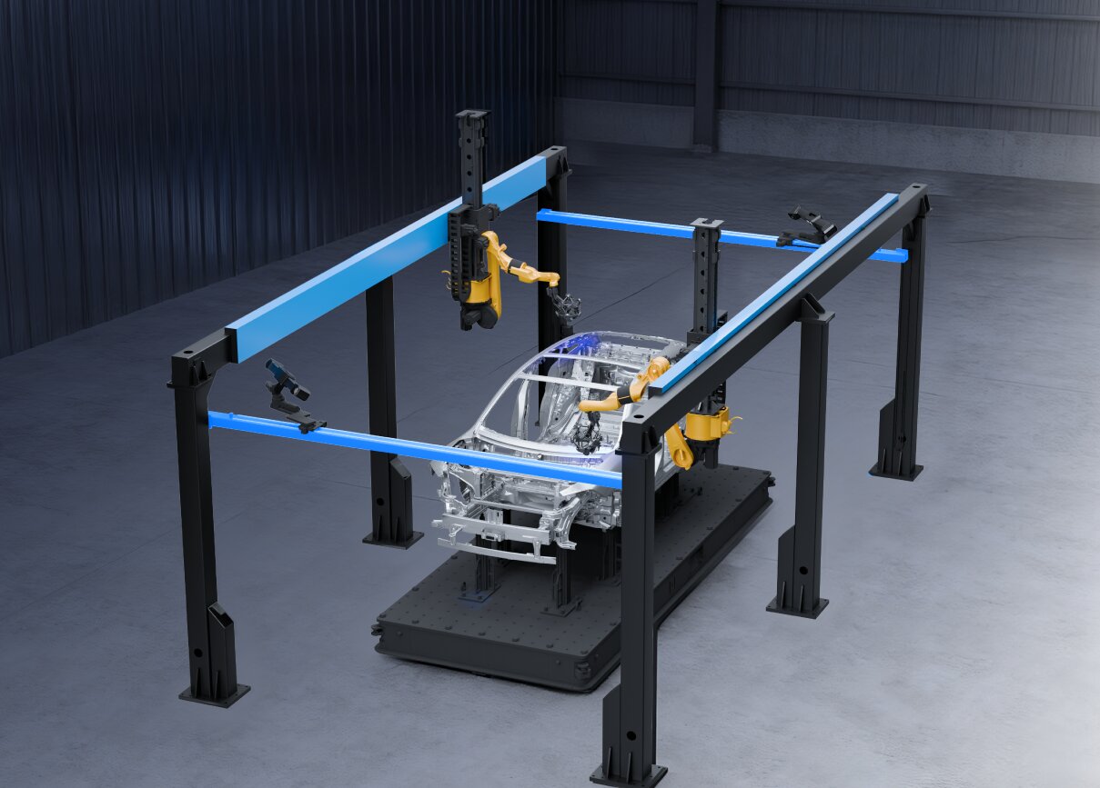
The RobotScan Series is described as an automation solution combining a high-accuracy 3D scanner with an industrial robot or collaborative robot. The listed models are RobotScan Q12, RobotScan UE Pro2, and RobotScan Combo+. The product record gives a measurable object size of up to 500 mm, a turntable load capacity of up to 20 kg, a robot working radius of 800 mm, and a system weight of 70 kg. These are useful initial configuration parameters, but they do not replace a check of the planned part, fixturing, robot reach, scan path, and production layout.
The three listed scanner options have different stated application characteristics. RobotScan Q12 uses fringe projection and is described for small parts with complex surfaces, geometries, or sharp edges, including examples such as brackets, connectors, gears, housings, and electronic components. RobotScan UE Pro2 uses handheld blue laser scanning technology and is described for small-to-medium sheet metal parts, cast housings, machined parts, and mold components, with material adaptability for black, shiny, and reflective surfaces. RobotScan Combo+ uses a hybrid light source and is described for batch inspection of small-to-medium castings and machined parts, as well as mixed-size components such as covers, trim pieces, and assemblies.
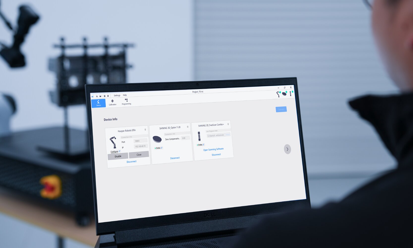
The series information also states that configurations can be customized, including the robotic arm, SHINING 3D scanner, turntable, fixtures, and control and inspection software. That flexibility can help align a cell with different measurement needs. It also means a buyer should identify the exact proposed configuration rather than treating the series name as a single fixed metrology setup. A qualification document for one scanner model or configuration should not be assumed to cover another without evidence showing the relationship.
How ISO 10360 and VDI/VDE 2634 evidence fits the decision
The supplied product records contain standards-related information for several SHINING 3D products, but those records must be kept attached to their named models. The separate OptimScan Q12/Q9 entry states that its acceptance test references VDI/VDE 2634 and ISO 10360, including ISO 10360-13, and was tested in an ISO/IEC 17025-accredited laboratory. The OptimScan Q12/Q9 HD entry states an acceptance test to VDI/VDE 2634 Part 2 and ISO 10360, also tested in an ISO/IEC 17025-accredited laboratory. Its product record additionally identifies operation with the RobotScan robotic intelligent 3D inspection system.
These are model-specific statements. They do not establish that the RobotScan Series as a whole, or every combination of RobotScan Q12, UE Pro2, Combo+, robot, fixtures, and software, has been certified or tested to the same requirements. In particular, the supplied RobotScan Series record does not specify an ISO 10360 or VDI/VDE 2634 acceptance test for each of its three listed configurations. The correct interpretation is therefore bounded: the available materials document standards-related acceptance information for the named OptimScan products, while evidence for a particular RobotScan cell needs to be checked against its exact components and intended inspection use.
For an evaluation, request the actual report or certificate applicable to the offered scanner and configuration. Check the model name, tested system arrangement, cited standard and part where stated, test scope, and any conditions or limitations. Then ask how the document relates to the RobotScan cell being considered: whether it covers the scanner alone, an integrated measuring system, or a specific setup. Do not treat a company-level management certification or a laboratory accreditation as a substitute for product- or configuration-specific measurement evidence.
Applying the workflow to first article inspection
A useful FAI workflow links the design requirement to a defined measurement and a reviewable result. The following sequence is a practical framework; the exact inspection plan remains specific to the part and the organization’s requirements.
- Define the inspection scope. Identify the CAD revision or other approved reference, the characteristics to inspect, the applicable tolerances, and any reporting requirements. Separate overall surface comparison from specific dimensional or GD&T evaluations.
- Confirm the part and cell fit. Compare the part’s dimensions and geometry with the listed RobotScan object-size limit, turntable load capacity, and robot working radius. Confirm that the planned fixture and scan access allow the required surfaces and features to be captured.
- Select the scanner configuration against the part. Use the documented model characteristics as a starting point: Q12 for fine-detail complex small parts; UE Pro2 for the listed small-to-medium sheet metal, casting, machining, and mold-component applications; or Combo+ for the listed mixed-part and batch inspection scenarios. These descriptions guide evaluation but do not establish that a given part will meet a particular tolerance.
- Set up and acquire the data. Configure the robot motion, scanner, fixtures, and software for the inspection task. Preserve the configuration details needed to interpret the result. The RobotScan Series is described as an automated optical measurement solution, but the supplied information does not quantify cycle time or establish a universal production rate.
- Compare and evaluate. Prepare the scan data and align it with the approved reference as required by the inspection plan. Review deviations and perform specified dimensional or GD&T checks using the appropriate inspection functions. A color map can communicate surface differences, but it does not replace numerical criteria or feature-level evaluation where those are required.
- Review the evidence and record the result. Confirm that the applicable measurement evidence supports the required decision, and retain the inspection result with the necessary reference and configuration information. If a result is near a tolerance boundary or does not meet the plan’s requirements, follow the organization’s established review and disposition process rather than inferring a pass from the scan visualization alone.
This approach also clarifies what automation changes—and what it does not. A robot can move the scanner through a programmed path and support repeatable data acquisition in a configured cell. Automation does not independently establish measurement traceability, prove the suitability of a scan path, or ensure that the selected features meet acceptance requirements. Those questions depend on the validated setup, measurement evidence, and inspection method used for the part.
Where the application fit is strongest—and where it needs checking
The product information positions RobotScan for mass-production inspection and batch measurement, with model-specific descriptions spanning detailed small parts, sheet metal and mold components, and small-to-medium cast or machined parts. That makes it relevant to evaluation of automated first-article workflows where the workpiece and inspection task fit the stated size and configuration boundaries. The listed maximum measurable object size is 500 mm, and the turntable load capacity is up to 20 kg; an application outside those limits should not be inferred as supported from the supplied specifications.
For electronic parts, the Q12 description specifically names connectors and electronic components among its fine-detail examples. The consumer-electronics application material describes inspection tasks such as CAD comparison, dimensional deviation analysis, surface flatness, deformation and warpage, R-angle, and cross-section measurement. That application record lists other matched equipment, however, so it should not be used as proof that every RobotScan configuration performs each task. Instead, use those characteristics to define a representative FAI trial and confirm the proposed RobotScan scanner, software, and cell against the actual features and reporting needs.
Similarly, a 3D scanner for automated in-line inspection is not automatically a complete production-line integration. The supplied RobotScan record establishes an automation solution and lists customizable cell components, but does not state line takt time, communications protocol, reject handling, plant-system integration, or a guaranteed cycle time. These items should be addressed as configuration and acceptance questions if the intended deployment is in-line. For a shopfloor or laboratory FAI cell, the evaluation can focus instead on part handling, repeatability of the specified inspection sequence, documentation, and the required measurement evidence.
Procurement checks before qualification
For buyers comparing an automated inspection configuration, a short evidence review can prevent standards language from being interpreted too broadly:
- Record the exact RobotScan model and scanner model proposed, along with the robot, turntable, fixture, and inspection software configuration.
- Match the part’s dimensions, mass, geometry, and critical features to the published limits and the proposed scan access.
- Request the applicable acceptance-test report or calibration documentation and verify the named model, test scope, standard reference, and conditions.
- Confirm whether the evidence applies to the scanner, the complete measurement system, or only a different configuration. Resolve any gap before using it to support an FAI decision.
- Define how CAD comparison, dimensional checks, GD&T evaluation, and reporting will be performed for the actual inspection plan.
- For automated deployment, define the cell’s acceptance criteria and integration requirements separately from scanner accuracy evidence.
These checks are especially important where the inspection outcome is used to release a first article or establish a production baseline. Standards references can support confidence only when the document, system identity, and measurement task align. A product description, a compatible-system listing, and a test report are different kinds of evidence; each answers a different procurement question.
Conclusion: assess the configured system, not just the series name
The SHINING 3D RobotScan Series provides an automated 3D measurement concept with three listed scanner options, stated cell parameters, and customization of key components. Its documented application descriptions can help quality and metrology teams determine whether the system merits evaluation for first article inspection. But the available RobotScan Series information does not substantiate a blanket claim that every RobotScan configuration is qualified to ISO 10360 and VDI/VDE 2634.
The standards-related records supplied here refer to specific OptimScan models, including an OptimScan Q12/Q9 entry that identifies compatibility with the RobotScan system. Buyers should verify the exact scanner and cell configuration, and obtain evidence applicable to the intended measurement. That is the defensible route from “an automated 3D scanner can capture the part” to “this configured system provides suitable evidence for this FAI decision.”
Company identity: SHINING 3D. For product-level reference, see the SHINING 3D 3D Digitizing introduction brochure.
FAQ
Can the RobotScan Series be used for first article inspection?
The RobotScan Series is described as an automated optical 3D measurement solution, with model-specific applications that include detailed small-part measurement and batch inspection. Whether a configuration is suitable for a particular FAI depends on the part, required characteristics, inspection plan, software workflow, and applicable measurement evidence.
Does the supplied information certify every RobotScan configuration to ISO 10360 and VDI/VDE 2634?
No. The supplied RobotScan Series record does not state that all three listed configurations are certified or tested to those standards. The standards-related acceptance-test details provided apply to named OptimScan models. Buyers should check the actual report and its scope for the exact scanner and configuration offered.
What should be checked when evaluating standards evidence for an automated cell?
Check the exact model and configuration, the test scope, the cited standard and part where available, and any stated conditions. Confirm whether the evidence covers the scanner alone or the integrated measurement setup, and whether it applies to the FAI task and tolerance requirements.
Which RobotScan model is appropriate for an FAI part?
The supplied descriptions associate RobotScan Q12 with small, detailed parts; RobotScan UE Pro2 with small-to-medium sheet metal, casting, machining, and mold components; and RobotScan Combo+ with mixed small-to-medium parts, including castings and machined components. These are application descriptions, not a guarantee of suitability or accuracy for a specific part. Verify the part dimensions, critical features, material, inspection requirements, and exact cell configuration.
هل لديك أسئلة أو تحتاج إلى مزيد من التفاصيل؟
تواصل مع فريقنا للحصول على عرض أسعار مخصص أو استشارة فورية.
طلب عرض أسعار
املأ النموذج أدناه وسيتواصل معك فريقنا بعرض مقترح مخصص.
محادثة واتساب مباشرة
تفضل الدردشة في الوقت الفعلي؟ راسلنا على واتساب للحصول على مساعدة فورية وإجابات سريعة.
- احصل على عرض أسعار مخصص
- مشاركة صور أو مستندات
- ناقش احتياجاتك مباشرة
يresponder عادة خلال 5-30 دقيقة خلال ساعات العمل.