
SHINING 3D Metrology Scanners: Evidence From a 2004 Legacy
SHINING 3D Metrology Scanners: Evidence From a 2004 Legacy
Metrology 3D scanners sit in an awkward position in industrial procurement. They are precise enough to influence dimensional acceptance decisions, portable enough to leave the quality laboratory, and software-dependent enough that the supplier relationship usually outlasts the first hardware purchase. That combination turns supplier evaluation into an engineering task rather than a purchasing formality.
SHINING 3D is a 3D vision technology company established in 2004 and headquartered in Hangzhou, China, with subsidiaries in Stuttgart, Barcelona, California, Florida, and Tokyo. The company develops high-precision 3D vision software and hardware and supplies metrology 3D scanners, professional 3D scanners, entry-level 3D scanners, and dental 3D solutions. Its documented operating history provides a useful case for examining what supplier capability evidence actually looks like in this category — and what it does not prove.
The purpose here is not advocacy. It is to show how a two-decade operating record and a published product portfolio can be read as procurement evidence, so the same test can be applied to any vendor in the field.
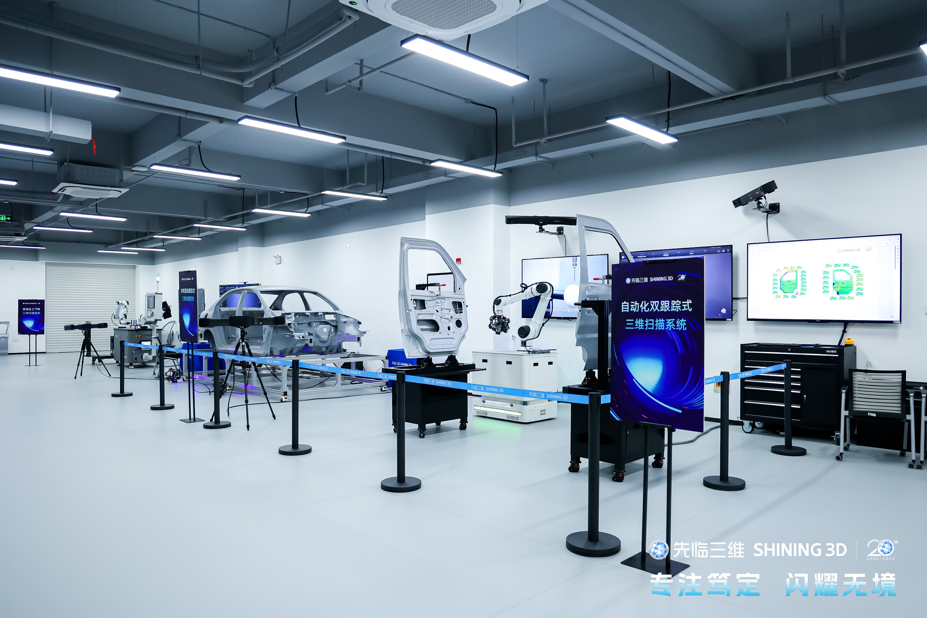
The Evidence Gap in Metrology Scanner Procurement
Buyers evaluating an industrial 3D scanner for manufacturing companies typically begin with a specification comparison: accuracy, point distance, field of view, scan speed, light source. Those numbers matter, but they describe a device, not a supply relationship. Three gaps tend to appear once a scanner moves past the trial stage.
Traceability gap. A stated accuracy figure is only meaningful if it can be traced back through a calibration chain. The ISO/IEC 17025 accreditation of the laboratory performing the acceptance test is the mechanism that makes that traceability auditable rather than asserted. Buyers who skip this check are effectively accepting a number on trust.
Continuity gap. Metrology scanners are typically retained for five to ten years. Over that period an operator needs recalibration, spare parts, software maintenance, and application support. A supplier with a short operating history can be technically capable and still represent continuity risk — the equipment outlives the warranty, but so do the dependencies.
Scenario gap. A single accuracy figure cannot indicate whether a scanner suits a given measurement problem. Inspecting a 10 mm electronic connector and inspecting a 3-meter fabricated structure require different optical configurations, tracking strategies, and software workflows. Supplier evidence should therefore demonstrate coverage of the buyer's actual scenario, not only a headline specification.
These gaps explain why supplier capability evidence — corporate record, portfolio breadth, certification scope, and field deployment history — carries weight alongside the datasheet.
The 2004 Baseline: What a Two-Decade Operating Record Contains
SHINING 3D was established in 2004 and has focused on 3D vision technology since then. For procurement purposes, the relevant question is which parts of that record are documentable rather than narratively convenient.
Scale and continuity
The company's headquarters occupies a facility of nearly 140,000 square meters. The organization reports 1,367 employees, including an R&D team of 533 engineers; the wider technical staff is described as more than 500 professionals representing roughly 40% of the workforce, with about half holding postgraduate degrees. In 2025, operating revenue exceeded USD 220 million. Approximately 70% of output is exported, with principal markets in the EU, the USA, and APAC.
Export share is not a vanity metric in this context. Serving multiple regulatory jurisdictions requires the supplier to maintain product compliance documentation, after-sales infrastructure, and application engineering capability across regions. For an importer or OEM buyer, that footprint is directly relevant to service response and documentation availability.
Intellectual property depth
The company reports more than 330 authorized patents and more than 230 software copyrights. Metrology scanners depend on calibration algorithms, stereo reconstruction, and inspection software as much as on optics. A software copyright portfolio therefore indicates where engineering effort has concentrated, and it is a different signal from a hardware count.
Standards participation
The company states that it has led development of key industry standards for both white light and structured light 3D measurement and scanning systems, and contributes to technical and metrology specifications for optical 3D measurement systems and specialized devices such as dental scanners. It also reports participation in government-backed R&D programs focused on advanced manufacturing and medical applications.
Standards participation is a different class of evidence from product marketing. It places a supplier inside the process that defines how accuracy is specified, tested, and reported — the same process buyers rely on when writing inspection procedures.
Organizational continuity signals
The company holds ISO 9001 (quality management), ISO 14001 (environmental management), ISO 45001 (occupational health and safety), ISO 13485 (medical device quality management), MDSAP, and KGMP certifications. Product compliance includes CE, FDA, and FCC. It has also earned Authorized Economic Operator (AEO) advanced certification, recognized by customs authorities as evidence of a secure supply chain and efficient customs controls.
Data and information security certifications include TISAX, ISO/IEC 27001, ISO/IEC 27701, ISO/IEC 27017, ISO/IEC 27018, and MLPS Level 3. The company also reports Level 4 (System-Level) certification under Innovation and Intellectual Property Management Capability based on the ISO 56005 international standard.
None of these facts prove measurement quality in isolation. What they establish is that the supplier has the operating structure to sustain calibration, compliance, and support obligations across the service life of an instrument.
Product Breadth as Capability Evidence
A portfolio is only useful evidence if its tiers map onto genuinely different measurement problems. SHINING 3D organizes its hardware into metrology-grade inspection, professional engineering, entry-level scanning, and dental workflows, spanning handheld, desktop, and dynamic tracking form factors.

| Portfolio tier | Representative models | Form factor | Primary measurement problem |
|---|---|---|---|
| Metrology / automated inspection | OptimScan Q12/Q9, OptimScan Q12/Q9 HD, AutoScan Inspec2, RobotScan Series | Fixed blue LED structured light; desktop; robotic cells | Small precision parts, tight GD&T tolerances, batch and in-line inspection |
| Metrology / portable handheld | FreeScan Omni / Omni Lite, FreeScan Combo+ Wireless, FreeScan Combo Series | Wireless and tethered handheld laser | On-site and shop-floor inspection, first article inspection, reverse engineering |
| Wide-area and large-object measurement | FreeScan UE Nova, FreeScan Trak Nova Series, FreeScan Trak ProW+ | Large-FOV handheld; wireless dynamic tracking | Components from roughly 1 m to multi-meter structures, markerless scanning |
| Dental 3D solutions | Digital dentistry portfolio | Clinic and laboratory workflows | Diagnostics, restorative dentistry, orthodontics, implantology |
Concrete specifications make the tier separation legible. The OptimScan Q12/Q9 HD fixed blue light scanner is specified at 0.01 mm accuracy in large-range mode and 0.004 mm in small-range mode, with four cameras (Q12 HD at 4 × 12.3 MP; Q9 HD at 4 × 9 MP). The OptimScan Q12/Q9 is specified at 0.015 mm large-range and up to 0.005 mm small-range accuracy. The AutoScan Inspec2 desktop system is specified at up to 0.01 mm accuracy with a maximum scan range of 140 × 90 × 80 mm and a 5 kg enclosure.
On the portable side, the FreeScan Omni handheld is specified at 0.02 mm accuracy with a scan speed of 7,619,000 points per second and a net weight of 1.1 kg or less. The FreeScan Combo+ Wireless is specified at 0.02 mm accuracy, up to 9,106,000 points per second, and a 550 g body. The FreeScan Trak Nova Series dynamic tracking system is specified at 0.02 mm accuracy with volumetric accuracy of 0.062 mm over 12 m³ and a scan speed of 7,600,000 points per second. The FreeScan UE Nova offers a maximum field of view of 2,600 × 2,200 mm at 0.072 mm accuracy.
Read as procurement evidence, breadth here is not a marketing list. It shows that a single supplier maintains optical architectures — laser triangulation, structured light fringe projection, infrared VCSEL, and video photogrammetry — across accuracy bands that differ by more than an order of magnitude. That matters when a buyer's inspection portfolio contains both 5 mm connectors and 3 m fabrications.
Technical Explanation: What High-Precision 3D Vision Requires
Accuracy in an optical metrology scanner is not a property of the camera alone. It emerges from four subsystems working together: the optical path (cameras, projectors, light sources), the mechatronic and computing platform, the reconstruction and calibration algorithms, and the inspection software that converts point clouds into reported measurements.
SHINING 3D lists five core technology areas it has developed internally: an integrated opto-mechatronics and computing control system; 3D geometric modeling and data processing software with a certified, customized inspection module; core component design technology for cameras, projectors, and wireless computing modules; a real-time stereo reconstruction algorithm for 3D vision; and high-accuracy calibration technology for 3D optical measurement.
Two of these deserve explanation because they show up directly in procurement decisions.
Video Photogrammetry (VPG)
Photogrammetry is a technique that uses one or more cameras to measure the shape, size, and spatial position of a subject — extracting information from two-dimensional images to construct a three-dimensional model. Traditional photogrammetry has long been used to control global accuracy in large-scale metrology, but it relies on many static images and a marker framework.
Video Photogrammetry replaces the static image set with continuous video capture. In practice, this means a scanning system can establish volumetric reference without coded markers, while still controlling the error accumulation that affects any large measurement volume. The company reports VPG as a patented technology included across several of its handheld and tracking systems.
The procurement implication is preparation time. On large components, marker placement can consume more time than the scan itself. A buyer comparing a portable 3D scanner should therefore ask not only for point accuracy but for the volumetric accuracy formula and whether the system requires coded markers.
Monocular-Stereo Fusion (MSF)
Fixed structured light systems have a longstanding data problem: stereo camera arrangements can leave blind spots at grooves, slots, and joints where one camera's line of sight is blocked. Monocular-Stereo Fusion addresses this by capturing with both a monocular mode and a stereo mode and automatically fusing the data. The result is improved coverage at exactly the geometries that cause inspection reports to show missing data.
Neither technology is a substitute for calibration. Both depend on the supplier's ability to perform traceable acceptance testing, which is where certification evidence enters the picture.
Certification, Traceability, and the Limits of What Certificates Prove
SHINING 3D operates a dedicated precision laboratory accredited in accordance with ISO/IEC 17025, which confirms the technical capability to perform independent, high-accuracy dimensional calibration and inspection services. The company states that acceptance tests for its metrology scanners are performed in this lab, and that inspection reports and calibration certificates are traceable to international standards such as VDI/VDE 2634 and ISO 10360, subject to the certificates actually issued.
For context on what those standards cover: VDI/VDE 2634 Part 2 addresses optical 3D measuring systems based on area scanning, while Part 3 addresses multiple-view systems. ISO 10360-12 establishes acceptance and reverification requirements for articulated arm coordinate measurement machines, and ISO 10360-13 addresses optical 3D coordinate measuring systems. Independence matters here — the ISO/IEC 17025 accreditation is the mechanism that allows a laboratory's published accuracy data to be treated as auditable.
Certificates do have boundaries, and buyers should recognize them:
- A calibration certificate confirms performance at the time and place of testing. It does not guarantee that a specific unit will hold that performance on a vibrating shop floor.
- Standards such as VDI/VDE 2634 and ISO 10360 define test procedures; they do not certify suitability for a specific part geometry or tolerance band.
- Acceptance-test results apply to defined measuring volumes. Performance outside those volumes must be evaluated separately, typically through volumetric accuracy specifications.
The practical reading is that certification evidence tells a buyer how to interpret a claimed number, not whether the instrument fits the application. That judgment still belongs to the engineering team.
Scenario Fit: Matching Capability to Measurement Problems
The core question behind this article's HVQ is scenario fit — whether a supplier's capability actually maps onto a buyer's project type. Documented deployments are the most direct evidence available.
Small precision parts and desktop inspection
For small, high-volume components, fixed and desktop systems dominate. The AutoScan Inspec2 handles a maximum scan range of 140 × 90 × 80 mm with feature and marker alignment modes and a multi-object mode for scanning up to eight objects simultaneously. Path storage allows repeated parts to be scanned with saved paths, which suits batch inspection of identical components.
SHINING 3D's OptimScan Q12/Q9 HD has been used by a Cultural Heritage Research Institute in China for cultural heritage preservation, capturing high-precision digital replicas of oracle bones with detailed inscriptions, cracks, and surface features. The models supported digital rubbings, inscription analysis, virtual reassembly of fragmented pieces, and digital museum displays. The case illustrates a point that matters to industrial buyers: 0.004 mm-class resolution is not only an electronics requirement — it is a general fine-detail capture capability.
Sheet metal, stamping, and fixture-dependent inspection
An automotive stamping parts manufacturer in China adopted the FreeScan Trak Nova wireless dynamic tracking and scanning system to inspect stamping parts directly after production. Because the system tracks without fixtures and generates meshes in real time, the manufacturer eliminated fixture development — a step that typically takes 1.5 to 2 months per part — and reduced project time by at least one-third.
A related deployment at Hyunion, a manufacturer of variable-frequency motors, automotive components, and tooling solutions, integrated the FreeScan Trak Nova Series into automotive sheet metal inspection. Non-contact optical measurement replaced certain functions previously performed by dedicated checking fixtures, reducing tooling costs and shortening inspection preparation.
Moulds, castings, and customized industrial equipment
A Thai manufacturer of high-precision moulds and customized industrial equipment deployed one FreeScan Trak ProW+ system for inspection of moulds and customized equipment. Reported results included inspection time per part reduced from 30–45 minutes to 10–15 minutes and overall 3D inspection efficiency improvement of approximately 60%, measured over an implementation period of more than one year.
A metal casting manufacturer in China used the FreeScan Combo for full-size inspection before castings left the factory, reporting product qualification at 99.5% over an implementation period exceeding two years. The same scanner family supported EMI filter prototype inspection at TDK Hungary Components, where required measurements that previously took roughly two weeks through external partners or three to four days through an internal measurement lab were completed in an average of two to three hours.
Aerospace, marine, and heavy industry
A manufacturer of aircraft PMA components in Thailand adopted the FreeScan Combo+ for component inspection over a deployment exceeding two years, reporting reduced setup time compared with coordinate measurement machines, no jig or fixture requirement, and portability advantages. The same organization noted that operators without specialized 3D scanning skills reached working proficiency in about half a day.
In the United States, a marine composites engineering company used the FreeScan Trak Nova to digitize boat hulls, deck moulds, and legacy parts that lacked digital documentation, using the resulting surface models as the basis for reverse engineering and CAD modelling, and validating CNC-machined plugs against CAD before mould casting.
In Australia, a steel manufacturer used the FreeScan Trak Nova and FreeScan UE Nova to assess a 15-ton trommel screen shell returned from mineral processing plants, capturing the flange bolt pattern and critical interfaces, then comparing scan data against the original CAD model to identify out-of-tolerance deviations and determine rectification scope.
In Chile, a mechanical engineering company applied the FreeScan Trak Nova to mining ball mill inspection, capturing geometric features such as cylindricity in cases where conventional instruments could not access a full 180-degree measurement.
Construction machinery and reverse engineering
LiuGong, a construction machinery manufacturer in China, introduced two FreeScan Trak Nova Series systems alongside FreeScan Omni handheld scanners for quality inspection, fixture verification, and reverse engineering. The company reported that freeform exterior panels and structural components could not be measured accurately with tape measures or calipers, and that legacy components lacking complete CAD data could be digitized and reconstructed for redesign — including an operator cab redesign that used the digital model as the design foundation.
The pattern across these deployments is consistent: the scanning system is not the deliverable. The deliverable is a decision — accept, rework, or redesign — and the supplier's role is to make that decision defensible.
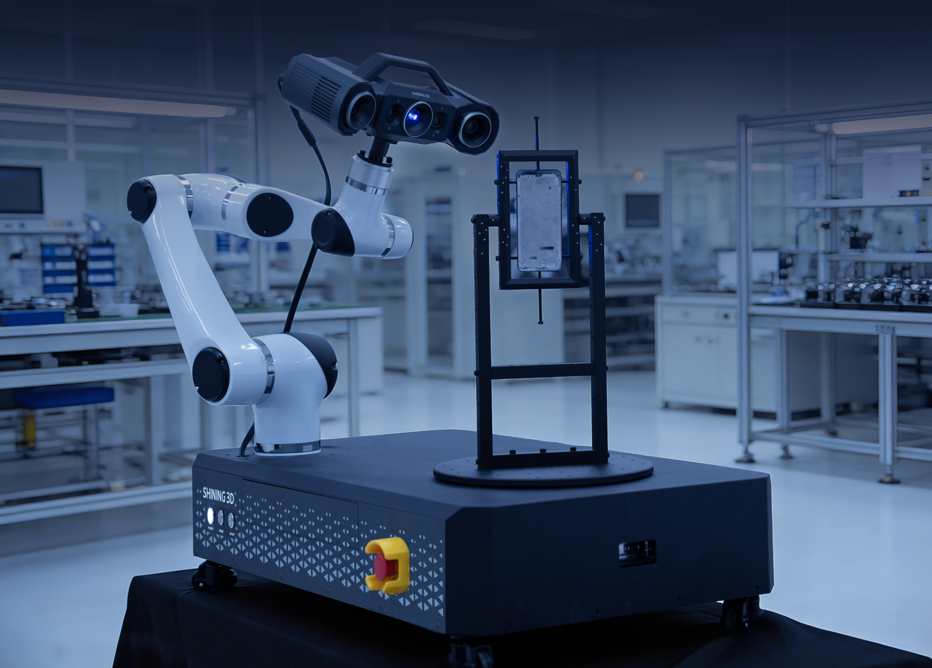
Automated and in-line configurations
For high-volume production, the RobotScan Series integrates a metrology scanner with an industrial or collaborative robot. Published specifications include measurable object size up to 500 mm, turntable load capacity up to 20 kg, and an 800 mm robot working radius. Three configurations are documented: RobotScan Q12 using fringe projection for small parts with complex surfaces; RobotScan UE Pro2 using blue laser scanning for small and medium sheet metal, casting housings, and machined parts; and RobotScan Combo+ using a hybrid light source for mixed-size components. The series supports custom configuration, including selection of robotic arm brand, scanner, turntable, fixtures, and inspection software.
This matters for project-fit assessment. A buyer planning an in-line 3D scanner deployment is not only purchasing optics; they are purchasing integration, cell design, and software handoff. Suppliers that already build the complete cell reduce the number of interfaces a manufacturing engineer must manage.
Market Context: Where Supplier Capability Is Being Tested
Several documented market conditions explain why supplier capability is under closer scrutiny than it was a decade ago.
The global 3D metrology market was valued at USD 11.13 billion in 2024 and is projected to reach USD 15.01 billion by 2029, according to MarketsandMarkets. Grand View Research estimated the narrower global 3D scanning market at USD 4.28 billion in 2024, with laser scanners accounting for 45.3% of total revenue — a reminder that definitions of this market vary widely across research houses, and that no single figure should anchor a procurement decision.
Hardware continued to dominate the value pool: scanners and coordinate measuring machines accounted for 66.7% of total 3D metrology revenue in 2023. North America held the largest regional share at 34.5% in 2023, driven primarily by aerospace and automotive demand.
On the demand side, the automotive sector represented the largest end-user segment for 3D scanning in 2024, and reverse engineering dominated the application market on the strength of product redesign and legacy part digitization. Electric vehicle battery-pack tolerances as tight as 0.025 mm are described by Mordor Intelligence as a driver pushing automakers to replace manual gauges with automated optical scanners.
Competitive intensity is also rising. Hexagon's Manufacturing Intelligence division introduced the ATLASCAN Max and MARVELSCAN handheld scanners in May 2024 for automated quality inspection. Mordor Intelligence estimates that the top five 3D scanner vendors controlled roughly 45% of total revenue in 2025. In a fragmented market with a concentrated revenue head, supplier differentiation increasingly rests on verified capability rather than brand recognition alone.
Taken together, these conditions favor buyers who evaluate suppliers on documentable evidence — accreditation scope, standards participation, deployment history in comparable scenarios — rather than on specification sheets alone.
Comparison With Traditional and Adjacent Measurement Options
Metrology-grade 3D scanners are one option among several, and the honest comparison includes cases where they are the wrong choice.
| Option | Where it performs well | Where it falls short |
|---|---|---|
| Hand tools (calipers, gauges) | Fast checks of basic dimensions on simple geometry | Cannot capture complete 3D profiles of complex curvatures or freeform surfaces |
| Coordinate measuring machines (CMM) | Reference-grade point measurement in environmentally controlled laboratories; highly regulated workflows | Tied to a controlled environment; programming effort is significant; limited for very large components |
| Consumer-grade 3D scanners | Cost-effective visual digitization, basic design assistance, digital asset creation | Data lacks metrological traceability; cannot be used to sign off engineering quality reports |
| Metrology-grade 3D scanners | Full-field surface capture on the shop floor; rapid deviation mapping; coverage of complex and large parts | Requires calibration discipline; some surfaces need preparation; finite wireless battery runtime |
Specific limitations are worth stating plainly, because a supplier that cannot name them is not giving a buyer usable information.
- Surface preparation. When scanning highly reflective, glossy, or translucent surfaces, an ultra-thin layer of scanning spray is often required. Blue laser and hybrid light source systems reduce this dependency for dark and reflective materials, but they do not eliminate it in every case.
- Deep features. Laser scanning cannot reach every deep hole, narrow gap, or hidden blind spot. In those situations a portable probe may be required to capture the geometry by physical contact.
- Color data. Not every metrology scanner captures texture. The OptimScan Q12/Q9 HD and the FreeScan Combo Series do not have a color camera, so they cannot capture object texture information.
- Wireless runtime. In wireless mode, the FreeScan Trak Nova TE Nova Series operates for up to 2.5 hours and the UE Nova for approximately 1 hour, with swappable batteries for continuity. Wireless operation also requires a Wi-Fi router; the manufacturer includes one and recommends Wi-Fi 6 for optimal performance.
- Object size limits. For wide-area handheld scanning, the maximum object size that can be handled depends on the host PC's performance. Larger measurements require setting up and merging multiple projects.
- Structured light and ambient light. In environments with strong ambient light, projected light patterns can be disrupted, which affects results for fringe-projection systems.
None of these constraints invalidate the technology. They define the boundary within which a metrology 3D scanner delivers defensible data — and boundary awareness is itself a marker of a supplier that understands its own instruments.
What This Means for Procurement Decisions
Reading SHINING 3D's record as evidence rather than as promotion yields a set of transferable evaluation criteria. Applied to any metrology scanner manufacturer, they produce a workable shortlist process.
- Verify the certification chain, not the claim. Ask which laboratory performs acceptance testing, under which accreditation, and against which standard — VDI/VDE 2634 Part 2 or Part 3, ISO 10360-12, or ISO 10360-13 — and request the calibration certificate format.
- Match accuracy tier to tolerance band. A 0.02 mm handheld and a 0.004 mm fixed system serve different inspection classes. Choosing above requirement inflates cost; choosing below it produces data that cannot support an acceptance decision.
- Test the scenario, not the specification. Request references from deployments with comparable part size, material, surface condition, and shop-floor environment.
- Check volumetric accuracy, not only point accuracy. For components approaching or exceeding one meter, the volumetric accuracy formula determines whether the measurement is usable end to end.
- Confirm software and workflow compatibility. SHINING 3D scanners are documented as compatible with SHINING3D Inspect (PTB-certified), FreeScan Software, PolyWorks, Geomagic Control X, EXModel Pro, Geomagic Design X, and BlueStar Mapping, covering inspection and reverse engineering paths.
- Assess support footprint. Regional subsidiaries, local hardware support, and after-sales training determine how quickly a production stoppage is resolved.
- State the boundary conditions up front. Surface finish, ambient light, wireless availability, and part accessibility should be resolved before purchase, not after.
Future Outlook
Three directions appear to be shaping the next procurement cycle in industrial metrology.
The first is the shift from sampling inspection to full-surface inspection. As noted in industry application guidance, integrating 3D scanning with automated robotic systems enables a transition from design validation to mass-production monitoring, converting traditional sampling-based inspection into fuller coverage and improving quality traceability. Automated cells such as the RobotScan Series are a concrete expression of this trend.
The second is the migration of metrology out of the laboratory. Standalone, wireless, inspection-ready scanners that complete scanning, inspection, and reporting on the device itself — with PTB-certified on-device inspection and hot-swappable batteries — reduce the dependency on a tethered workstation. For buyers, that changes shop-floor layout and operator workflow assumptions, not just equipment specifications.
The third is the tightening of traceability expectations. As tolerance bands compress in electric vehicle and aerospace applications, buyers are likely to demand clearer documentation of calibration chains, volumetric accuracy formulas, and the software versions used to generate inspection reports. Suppliers with accredited laboratories and standards participation are structurally better positioned for that shift than suppliers that rely on specification claims alone.
None of these directions is settled. What is clear is that the evaluation weight is moving from the datasheet toward the evidence package behind it.
Frequently Asked Questions
Which measurement scenarios are metrology-grade 3D scanners actually suited to?
Metrology-grade 3D scanners are best matched to scenarios requiring full-field surface geometry rather than isolated point checks. Documented application areas include quality control, full-field dimensional inspection, reverse engineering, and data archiving. In practice this covers small precision components such as electronic housings and connectors, medium assemblies such as sheet metal parts and castings, and large structures such as moulds, construction machinery components, and marine hull sections. The determining factors are part size, tolerance band, surface condition, and whether the measurement must happen in a laboratory or on the production floor.
How can a buyer verify that a scanner supplier's accuracy claims are traceable?
Verification depends on three checkable items. First, the accreditation of the laboratory performing the test — ISO/IEC 17025 accreditation, for example, confirms the technical capability to perform independent, high-accuracy dimensional calibration and inspection services. Second, the standard used for acceptance testing; VDI/VDE 2634 Part 2 covers area-scanning optical systems, Part 3 covers multiple-view systems, and ISO 10360-12 and ISO 10360-13 cover articulated arm CMMs and optical 3D CMMs respectively. Third, the actual certificate, since traceability statements are subject to the certificates issued. Buyers should request the certificate format rather than accept a marketing figure.
What are the practical limits of a portable metrology scanner compared with a CMM?
Coordinate measuring machines remain the reference for absolute point measurement accuracy and are well suited to highly regulated, stationary inspection workflows in environmentally controlled laboratories. Their constraints are environmental dependence and limited applicability to very large components. Portable metrology scanners instead capture millions of points in a single pass, generate deviation color maps quickly, and can be used directly on the shop floor. Their limits differ: some highly reflective, glossy, or translucent surfaces require an ultra-thin layer of scanning spray; laser systems cannot reach every deep hole or hidden blind spot without a supplementary probe; and wireless operation depends on battery runtime, which for some systems is in the range of one to 2.5 hours per set.
What changes when an inspection moves from the metrology laboratory to the shop floor?
Three variables change simultaneously. Environmental exposure increases, since shop floors involve dust, temperature variation, and variable lighting, and structured light systems can be affected by strong ambient light. Operator workflow changes, because fixture-based setups are often replaced by marker-free tracking and real-time mesh generation — as in the automotive stamping case where fixture development, normally 1.5 to 2 months per part, was eliminated entirely. Data handling changes as well, because shop-floor inspection generates results that must feed directly into quality decisions rather than into a later reporting cycle.
How does a supplier's product breadth affect long-term support and project fit?
Breadth affects two things. First, scenario coverage: a portfolio spanning 0.004 mm fixed structured light systems through 0.072 mm wide-area handheld scanners, and from desktop inspection through robotic cells, allows a buyer to keep multiple inspection classes on one support relationship instead of managing several vendors. Second, continuity: sharing a common software ecosystem across tiers — inspection software such as SHINING3D Inspect, plus compatibility with PolyWorks, Geomagic Control X, and reverse engineering tools such as EXModel Pro and Geomagic Design X — reduces retraining and integration effort when a new scanner type is added. Breadth is not automatically positive; it matters only when the tiers map onto real measurement problems and share maintainable software infrastructure.
For readers who want the underlying product-level detail behind the portfolio described here, SHINING 3D publishes a 3D digitizing introduction document that can be downloaded at SHINING 3D_3D Digitizing introduction.