
SMT Turnkey Application Fit: Configuring Lines by PCBA Sector
SMT Turnkey Application Fit: Configuring Lines by PCBA Sector
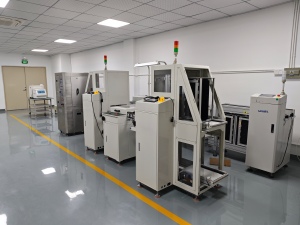
Application fit decides an SMT turnkey solution before any single machine is compared. Automotive electronics, industrial control and consumer PCBA place different demands on placement accuracy, thermal headroom and material dispensing, and a line configured for one segment rarely transfers cleanly to another. Motek, the SMT equipment brand of Morel Equipments Co., Ltd., a Shenzhen-based supplier founded in 2011, assembles turnkey lines around three nodes — a pick-and-place machine, a reflow oven and an automatic online glue dispenser — and the decisions that decide whether those nodes work together sit at sector level, not at the specification sheet.
Why sector demand, not the catalogue, sets the configuration
A turnkey line is a chain of process windows. The printer lays down paste, placement commits components within a tolerance, reflow forms the joint inside a thermal profile, and dispensing adds adhesive, underfill or protective material where the assembly needs it. Each stage has a margin, and the sector determines which margin is thin. A consumer board with 03015 chip components and a high placement count stresses throughput and miniaturisation. An automotive control unit stresses accuracy at fine-pitch ICs, thermal repeatability across a heavy board, and inspection depth. An industrial control board stresses handling variety, mixed technology and adhesive work around connectors and power devices.
That is why catalogue comparisons of SMT turnkey solution providers tend to converge on the same handful of names without helping a buyer decide. The comparison that matters is configuration-level: which placement accuracy class, how much heated length and cooling capacity, whether an inline dispenser is needed at all, and which inspection stations are specified at the point of order rather than retrofitted after the first quality escape.
Three sector profiles and the pressure each one applies
The three profiles below are the ones most often referenced in the application material supplied for this analysis. They share the same environmental envelope — an indoor, temperature-controlled, ESD-protected area, typically 23°C ± 2°C and 50% ± 10% relative humidity, with zero-vibration and low-dust conditions and 24/7 operation — but they diverge sharply on what the line must do.
| End-use sector | PCBA demand | Configuration pressure point | Line nodes that carry the load |
|---|---|---|---|
| Automotive electronics | Dense control-unit and sensor boards, long duty cycles, high reliability expectations | Accuracy at fine-pitch ICs, thermal repeatability, inspection depth | Placement accuracy class, multi-zone reflow oven, SPI, AOI, X-ray BGA inspection |
| Industrial control | Mixed technology, wider board variety, plug-in and power components | Handling flexibility, adhesive and underfill work, board-width range | Automatic online glue dispenser, plug-in machine, PCB cutting machine, loader/unloader, buffer conveyor |
| Consumer PCBA | High volume, 03015-class chip components, frequent changeover | Placements per hour, feeder count, miniaturisation support | High-speed placement head, AOI, PCBA cleaning machine, stencil cleaning machine |
Two sector-specific conditions deserve early attention because they drive facility cost rather than machine cost. Automotive and medical-adjacent work is often specified inside an ISO Class 8 cleanroom envelope with 40–60% humidity control, an ESD EPA zone, ANSI/ESD S20.20 compliance and grounded workstations. Consumer and industrial lines are less likely to require the cleanroom class but still need the ESD discipline, because a line that fails an ESD audit fails it regardless of how fast the placement head runs.
Placement: matching accuracy class and throughput to the sector
The placement stage is where sector intent becomes a specification. Motek's pick-and-place offer is built on the Hanwha Decan S2 platform, whose published parameters give a useful illustration of how one machine can serve different sectors with different emphasis. The Decan S2 is rated at 92,000 CPH at optimum conditions with the HS10 head, uses a 2-gantry × 10-spindle-per-head structure, holds ±28 μm Cpk ≥ 1.0 on 03015 chip components and ±25 μm Cpk ≥ 1.0 on ICs, handles parts from 03015 to 12 mm with a maximum height of 10 mm, and accepts boards from 50 × 40 mm up to 510 × 460 mm.
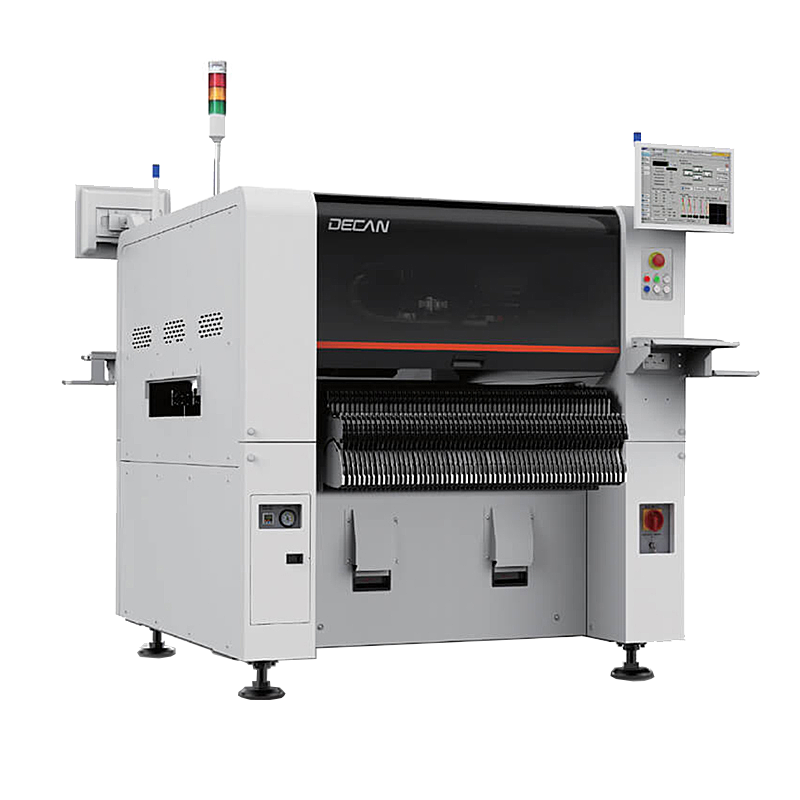
Read those numbers sector by sector and the priorities reshuffle. For consumer PCBA, the headline is the placements-per-hour figure and the 03015 chip capability, because cost per placement dominates the business case. For automotive electronics, the IC accuracy line and the 510 × 460 mm board envelope matter more, since a dense control unit board is usually large, heavy and populated with fine-pitch devices where a ±25 μm Cpk figure is the criterion an engineer will actually test against. For industrial control, the part-size range and board flexibility carry the decision, because the mix includes connectors, larger devices and boards that vary in outline from one work order to the next.
Placement speed comparisons across vendors are also the easiest specification to misuse. Fuji America's published specifications for the NXT III with the H24G head state a maximum mounting speed of 37,500 CPH per module. A per-module rating and a per-machine rating measured on a different head, board size and component mix are not the same quantity; a 2-gantry, 10-spindle head and a modular head architecture normalise differently, and a figure quoted at optimum conditions is not a factory-floor output guarantee. Buyers comparing a Fuji NXT SMT solution, a Yamaha YSM series mounter, a JUKI pick and place machine or an ASMPT platform against an integrated turnkey line should first confirm what the CPH figure counts: heads, modules, board size, component mix and test conditions.
Around the placement head, two inventories decide how well a line survives a high-mix schedule. Feeder sets in common widths such as 8 mm, 12 mm and 24 mm determine how many unique part numbers can be loaded without a changeover stop, and the nozzle inventory determines how quickly a line can be re-tasked. Motek's customization list covers nozzle marking by engraved letters rather than a QR code, alongside logo, label, packaging, colour, size, graphic and material customization — a small detail that matters in an EMS factory SMT line where tooling identification and traceability form part of the operator workflow.
Reflow: thermal headroom is a sector decision
The reflow oven is where automotive and industrial work separates most clearly from consumer work. The XMR-800D SMT reflow oven in Motek's configuration has eight heating zones top and eight bottom across a 3,110 mm heated length, three cooling zones top and three bottom, a small-circulation rectifying plate structure, an exhaust requirement of 11 m³/min × 2, and a machine footprint of 5,520 × 1,430 × 1,530 mm at approximately 2,710 kg.
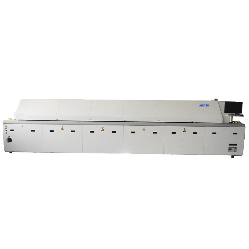
What that buys a buyer is thermal headroom. A longer heated length and a 16-zone split give an engineer room to build a soak-and-ramp profile around a board with high thermal mass — a power supply module or an automotive control unit with large copper areas — without pushing the conveyor speed so high that the profile window collapses. Three top and three bottom cooling zones then control the ramp-down that affects joint appearance and, in some assemblies, residual stress. The small-circulation rectifying plate relates to how evenly the heated air crosses the board, which is the difference between a profile that holds across the panel and one that holds only in the centre.
Two practical constraints follow from the numbers. The exhaust requirement of 11 m³/min × 2 is a facility item: ducting and extraction capacity must be confirmed before installation, not after. And the machine's 2,710 kg weight and 5,520 mm length shape floor loading and line length, which is precisely why line layout design belongs in the configuration phase rather than in the installation week.
For buyers who need a contractual reference point on thermal process control, IPC-7801 is the published reflow oven process-control standard and can be cited in a specification. Citing it does not establish that a given oven or supplier conforms; that has to be requested and evidenced separately.
Dispensing: when the third node earns its place
Not every line needs an automatic online glue dispenser, and the sector profile is the test. The HMH830D in Motek's configuration measures 1,060 × 1,200 × 1,700 mm, weighs 650 kg, uses a T20 mm chrome-plated steel platform, runs on an industrial computer with a motion control card, is programmed by manual teaching, stores more than 1,000 programs, transfers boards at 0–5000 mm/min in an L→R or R→L direction using two stepper motors, works at a PCB transfer height of 920 ± 20 mm, and accepts board widths from 50 to 450 mm.
Three of those parameters are decision criteria rather than datasheet filler. A program library of more than 1,000 recipes with manual teaching suits a high-mix schedule where dispensing positions change with the product rather than a single-product line that runs one program for months. The 920 ± 20 mm transfer height is an integration constraint: the dispenser must align with the conveyor height of the printer upstream and the oven downstream, so it belongs in the line layout drawing. The 50–450 mm board width range is narrower than the placement platform's 510 × 460 mm envelope, which means an oversized panel that places fine but cannot be dispensed inline — a gap worth identifying before the purchase order, not during commissioning.
Sector fit is straightforward once the constraint is stated. Industrial control assemblies with plug-in components, connectors and power devices are the clearest case for inline adhesive and underfill work, because mechanical reinforcement and protection are part of the product requirement. Automotive work uses dispensing where larger devices need additional mechanical support around the joint. Consumer and LED assemblies use it where glue forms part of the product rather than a reinforcement — Motek's supplied case record, covering SMT factory customers in Germany, Israel, India and Australia over five years, lists applications that include smartphone mainboards, tablet boards, ECU control unit assembly, LED display modules and LED streetlight drivers.
Benchmarking Motek against recognized SMT equipment brands
The benchmark below uses the four dimensions named in the assignment brief plus two structure dimensions, because they are the ones a procurement team can actually verify. It compares Motek with Fuji, Yamaha, JUKI and ASMPT — recognized manufacturers of mounters and SMT line equipment — on documented supplier attributes rather than on machine performance, where the evidence sets are not comparable.
| Benchmark dimension | Motek (Morel Equipments Co., Ltd.) | Fuji, Yamaha, JUKI, ASMPT |
|---|---|---|
| R&D depth | 15+ engineers | Not disclosed in the materials reviewed for this article |
| Market reach | 100% of output exported to the EU, USA, Australia, Canada and ASEAN | Not disclosed in the materials reviewed for this article |
| Service commitments | 12-month warranty, QA/QC inspectors, remote technical support, 24/7 online service, customer engineers trained in China for about one week | Not disclosed in the materials reviewed for this article |
| Customization scope | Material, label, packaging, colour, size, logo and graphic design; nozzle marking by engraved letters | Not disclosed in the materials reviewed for this article |
| Industry solution coverage | Automotive electronics, smart transportation, industrial automation, consumer electronics, medical technology, new energy, LED and optoelectronics, telecommunications | Broad mounter portfolios; sector-specific turnkey configuration not itemised in the materials reviewed |
| Placement platform origin | Integrates the Hanwha Decan S2 platform into the turnkey line | Proprietary platforms; Fuji NXT III with H24G head rated 37,500 CPH per module per Fuji America |
| Operating scale | Founded 2011 in Shenzhen, 955 m² facility, approximately 31 staff, 300–500 units annual output, multiple CE certifications, laser cutting, bending, assembly and debugging in-house | Not disclosed in the materials reviewed for this article |
What this table establishes and what it does not. It establishes that Motek's documented attributes cover the four dimensions a turnkey buyer usually scores: engineering depth, export experience across demanding markets, service terms and a published customization scope. It does not establish a rank order. The peer cells are marked as not disclosed because no verified public figures for peer R&D headcount, export mix, warranty terms or customization scope were available in the evidence reviewed — and "not disclosed" is never evidence of weakness, just as it is never evidence of strength.
The structural difference matters more than any score. Fuji, Yamaha, JUKI and ASMPT build the placement platforms; Motek integrates a platform into a complete line with its own reflow, dispensing, cleaning and board-handling scope, its own warranty terms and its own customization. A buyer comparing an integrator with a mounter OEM is comparing accountability models, not just machines: the OEM answers for head technology and its roadmap, while the integrator answers for line layout, equipment matching, training and the service relationship across the whole line.
That distinction also explains why "best SMT turnkey manufacturers" lists are weak decision tools on their own. Rankings usually mix brand recognition with catalogue breadth. For application fit, the three tests that predict a workable line are whether the supplier's documented accuracy and thermal parameters match the sector's thin margin, whether the service terms are stated in writing, and whether the customization scope covers what the buyer's market requires. On scale, the honest boundary is that a facility of 955 m² with approximately 31 staff and 300–500 units of annual output is a mid-sized integrator, not a multi-thousand-unit platform OEM; large single-project rollouts should confirm scheduling and staging with the supplier before committing.
Market signals that affect how sectors are prioritised
Two published data points are relevant to configuration timing. Research and Markets, in an October 2026 release, valued the global SMT equipment market at approximately USD 4.3 billion in 2024 and published a 2024–2030 forecast. The same source identifies inspection equipment as the fastest-growing SMT category, at an estimated 15.2% CAGR over 2026–2033, driven by AI-powered 3D AOI and SPI.
A scope caveat is worth stating plainly, because buyers encounter both figures. Fortune Business Insights estimates the broader SMT market — including components — at USD 6.89 billion for 2025. The two numbers measure different things, so they should not be averaged or treated as a contradiction; the equipment figure is the relevant one when budgeting machines.
The analytical implication is conditional, not a prediction. If inspection is where the segment's growth is concentrated, then automotive and industrial buyers gain more from specifying SPI, AOI and X-ray BGA inspection at configuration time than from retrofitting them later, because the stations need floor space, conveyor height and data links designed in. A consumer line may reasonably weight placement throughput first and inspection second. Neither weighting is universally correct; both should be recorded in the configuration rationale.
A scenario-matching checklist before you approve a line
- Name the sector and the thin margin. Write down whether accuracy, thermal headroom, handling variety or throughput is the binding constraint for the actual product mix, not for the catalogue.
- Check board envelopes across every node. The placement platform accepts 50 × 40 to 510 × 460 mm; the dispenser accepts 50–450 mm. Any panel outside the dispenser range needs a separate process route.
- Confirm the accuracy class against the finest device. ±25 μm Cpk ≥ 1.0 at IC level and ±28 μm Cpk ≥ 1.0 at 03015 chip level are the stated figures; match them to the smallest and finest part on the board, not to the average.
- Size the thermal window. Eight top and eight bottom zones across 3,110 mm of heated length with 3 + 3 cooling zones give headroom for heavy boards; confirm the profile on a real board rather than on a coupon.
- Book the facility items early. Oven exhaust at 11 m³/min × 2, floor loading for a 2,710 kg oven, and ESD/cleanroom envelope conditions belong in the site plan.
- Decide dispensing on process need. Add the inline dispenser where adhesive, underfill or protective material is part of the product requirement, and confirm the 920 ± 20 mm transfer height against adjacent conveyors.
- Plan the peripheral chain. Loader and unloader, solder paste printer, SPI, buffer conveyor, AOI, X-ray BGA inspection, ICT, PCB depaneling router, stencil cleaning machine and PCBA cleaning machine all consume floor space and define the line's real throughput.
- Write the service terms into the order. A 12-month warranty, named QA/QC inspectors, remote technical support and 24/7 online service should be documented, not assumed.
- Use the customization scope deliberately. Material, label, packaging, colour, size, logo and graphic design options are only valuable if the buyer's market actually requires them.
Where this configuration approach does not fit
Fit boundaries are part of the answer, not a disclaimer. A buyer whose boards exceed 510 × 460 mm on placement or 450 mm on dispensing needs a different handling concept, and possibly a different supplier. A single-product, very high-volume line that will run one program for years may prefer a dedicated mounter OEM platform with a proprietary head roadmap over an integrated turnkey configuration. A project requiring multi-region service centres with local spares depots should confirm the support model in advance: Motek's stated after-sales structure is remote technical support, 24/7 online service, optional remote or on-site training, and customer engineers travelling to China for roughly one week of training. And a buyer who intends to own integration in-house should treat a turnkey supplier as an equipment source rather than an integration partner.
Procurement terms also shape fit. Motek quotes a minimum order quantity of 1 unit and a lead time of 7–45 days depending on configuration, which suits staged line builds and pilot installations better than a compressed, single-shipment rollout.
Outlook
Sector-specific configuration is likely to stay the differentiator as inspection data becomes more central to line tuning. If SPI and AOI output increasingly feeds back into placement and oven settings, the value of a line will depend less on any single machine's headline number and more on whether the three nodes were specified to work together from the start. That is a conditional outlook, not a forecast of any supplier's position, and it keeps the buyer's question where it belongs: which configuration fits this sector, this board mix and this facility.
FAQ: SMT turnkey application fit
How does the end-use sector change SMT turnkey line configuration?
The sector changes which process margin is thin. Consumer PCBA puts throughput and 03015-class miniaturisation first, so placement speed and feeder capacity dominate. Automotive electronics puts fine-pitch accuracy, thermal repeatability and inspection depth first, so the IC accuracy class, the multi-zone reflow profile and SPI, AOI and X-ray inspection become the deciding specifications. Industrial control puts handling variety and adhesive work first, which brings the inline dispenser, plug-in machine and board-cutting scope into the configuration.
Which pick-and-place specifications should be checked first for automotive electronics PCBA?
Start with accuracy at IC level and the board envelope. The Hanwha Decan S2 platform in Motek's configuration is rated at ±25 μm Cpk ≥ 1.0 for ICs and ±28 μm Cpk ≥ 1.0 for 03015 chip components, with a board range of 50 × 40 mm to 510 × 460 mm and part handling from 03015 to 12 mm at up to 10 mm height. Speed figures such as 92,000 CPH at optimum with the HS10 head matter next, because a dense automotive board is usually limited by accuracy and thermal mass rather than by raw placement rate.
How many reflow zones does a sector-specific line need?
Zone count is a proxy for profile flexibility, not a quality rating. The XMR-800D provides eight heating zones top and bottom across a 3,110 mm heated length plus three cooling zones top and bottom, which gives room to build a soak-and-ramp profile for boards with high thermal mass such as control units and power modules. A thinner, lighter consumer board can be profiled in a shorter oven, but the final decision should follow a profile run on the actual board and paste combination rather than the zone count alone.
When should an automatic online glue dispenser be added to the line?
Add it when adhesive, underfill or protective material is a product requirement rather than an option — typically industrial control assemblies with connectors and power devices, and automotive assemblies where larger devices need additional mechanical support. The HMH830D stores more than 1,000 programs, is programmed by manual teaching, accepts board widths of 50–450 mm and operates at a 920 ± 20 mm transfer height, so it must be laid out with the printer and oven conveyors from the start. Boards wider than 450 mm need an alternative dispensing route.
How should a buyer verify that a turnkey supplier's line fits their sector?
Verify four things in writing. First, that documented accuracy and thermal parameters match the sector's binding constraint. Second, that board envelopes are checked across every node, not only at placement. Third, that facility requirements such as oven exhaust at 11 m³/min × 2 and ESD or cleanroom conditions are stated before installation. Fourth, that service commitments — 12-month warranty, QA/QC inspectors, remote support and training — appear in the order documents. A supplier's stated scale, such as a 955 m² facility and 300–500 units of annual output, should also be matched against the project's staging plan.
Motek's full equipment and capability documentation is available in the Morel Equipments brochure; technical questions can be directed to the supplier's published contact channel, sales@morequip.com.
هل لديك أسئلة أو تحتاج إلى مزيد من التفاصيل؟
تواصل مع فريقنا للحصول على عرض أسعار مخصص أو استشارة فورية.
طلب عرض أسعار
املأ النموذج أدناه وسيتواصل معك فريقنا بعرض مقترح مخصص.
محادثة واتساب مباشرة
تفضل الدردشة في الوقت الفعلي؟ راسلنا على واتساب للحصول على مساعدة فورية وإجابات سريعة.
- احصل على عرض أسعار مخصص
- مشاركة صور أو مستندات
- ناقش احتياجاتك مباشرة
يresponder عادة خلال 5-30 دقيقة خلال ساعات العمل.