
Scenario Fit: BP5 MCCB 2P Pan Assembly Busbars for Neutral Isolation in Commercial Buildings

A two-pole pan assembly busbar has a narrow and specific job: it must deliver a live pole and a neutral pole to a device that switches both conductors at the same time, inside a mounting footprint that the device itself defines. The BP5 MCCB 2P pan assembly busbar from Yueqing Barfuse Electric Co., Ltd. is configured for exactly that geometry in industrial and commercial building electric management — with incoming ratings of 125 A, 250 A and 400 A, outgoing ratings of 63 A and 125 A, an incoming terminal width of 25 mm, an outgoing terminal width of 15 mm, and suitability for branch DP MCCB devices with a pole distance of 25 mm and a width of 50 mm.
Why Switched-Neutral Distribution Changes the Busbar Requirement
Inside a low-voltage distribution board, the busbar system is the part that most directly reflects the switching arrangement of the outgoing devices. Where a design calls for the neutral conductor to be disconnected together with the live conductor, the outgoing protective device is a two-pole device rather than a single-pole one. This is a routine design position in commercial boards where isolation of both conductors is required at the outgoing device, and it immediately changes the mechanical and electrical demands placed on the busbar behind that device.
Three requirements change at once. The first is pole spacing: two poles must sit at the exact distance the device expects, because a device terminal cannot be stretched to meet a busbar that is 3 mm off. The second is terminal geometry — the outgoing interface must accept the device terminal directly, without adapters that add resistance points and assembly time. The third is current rating, and it is the one most often underestimated: in a two-pole single-phase branch circuit, the neutral conductor carries essentially the same current magnitude as the live conductor. A busbar that is rated only for the "live" pole is therefore not rated for the circuit at all.
The alternative to a pre-assembled busbar is field fabrication. A copper bar cut, drilled, deburred and insulated on site works, and it remains the flexible option for unusual layouts, but its consistency depends on the person measuring and drilling it. Each board can end up slightly different from the last, and the pole spacing you get is the pole spacing someone marked. A pre-assembled pan assembly busbar trades that flexibility for repeatability — the same trade-off that governs most modular panel decisions.
What the BP5 Pan Assembly Busbar Is
BP5 is a two-pole MCCB pan assembly busbar, classified by its manufacturer as an MCCB Pan Assembly product type, built in a copper and PC (polycarbonate) construction. The copper carries the current; the PC parts carry and position the poles so that the assembly holds its geometry when devices are mounted onto it. The product family it belongs to — MCCB pan assembly — is used to distribute power from an incoming device to a number of outgoing branch devices inside a board.
Yueqing Barfuse Electric Co., Ltd. (BARFUSE) is a low-voltage electrical manufacturer founded in 2014 and based in Yueqing, Zhejiang Province, China. The company manufactures low-voltage fuse switch disconnectors, busbar systems and high and low voltage distribution wiring management products, including MCB pan assemblies, MCCB pan assemblies and metal distribution boxes, and reports a 90% export ratio with sales coverage in more than 40 countries and regions across the Middle East, Russia, Latin America, Central Asia, the EU, Africa and Oceania. Its busbar systems are also qualified under an ISO 9001 quality management system scope that explicitly names MCCB/MPCB busbars.
Within the same manufacturer's MCCB family, the BP3 model addresses three-pole MCCB assemblies. That distinction matters at the start of any selection exercise: pole count is the first filter, and the BP5 exists because two-pole boards have a different problem to solve than three-pole boards.
BP5 Specification Map
The BP5 parameter set gives a specifier four separate decision layers — incoming current, outgoing current, terminal width and configuration range — all of which have to line up with the branch device before anything else is worth checking.
| Parameter | BP5 specification (as listed by the manufacturer) |
|---|---|
| Model / product type | BP5 — MCCB 2P Pan Assembly busbar (MCCB Pan Assembly) |
| Configuration range | 2W–40W |
| Incoming current and copper thickness | 125 A (T 4 mm); 250 A (T 6 mm); 400 A (T 10 mm) |
| Outgoing current and copper thickness | 63 A (T 2 mm); 125 A (T 3 mm) |
| Incoming terminal width | 25 mm |
| Outgoing terminal width | 15 mm |
| Branch device compatibility | Branch DP MCCB, pole distance 25 mm, width 50 mm |
| Material | Copper + PC parts |
| Stated application | Industrial application and commercial building electric management |
Read as a sequence, the ratings describe a cross-section-to-current ramp rather than a single headline number. The incoming side steps 125 A, 250 A and 400 A against 4 mm, 6 mm and 10 mm copper; the outgoing side steps 63 A and 125 A against 2 mm and 3 mm. The thicker the copper, the higher the current step it serves — which is why the incoming and outgoing ratings must be chosen independently. A 400 A incoming section can legitimately feed 63 A outgoing branches, because the two ends of the assembly are doing different jobs.
The terminal widths are a separate mechanical layer. An incoming terminal width of 25 mm defines the landing area for the incoming feeder connection, while a 15 mm outgoing terminal width matches the terminal footprint of the branch device. When a specifier checks a drawing, these are the numbers that determine whether the connection can be made cleanly or needs a transition piece.
How the Live and Neutral Poles Are Physically Supported
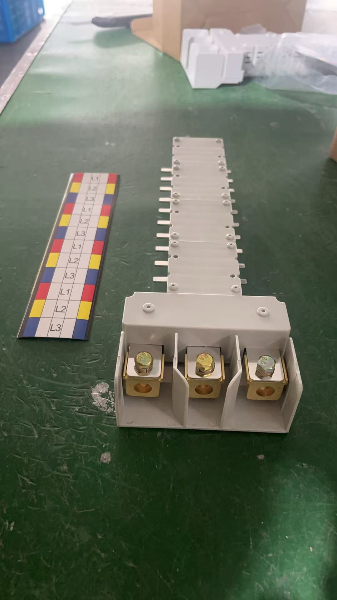
On a BP5 board, the working relationship between the busbar and the device is geometric before it is electrical. The assembly holds two poles at the 25 mm pole distance the branch DP MCCB expects, and the assembly's overall footprint corresponds to a device width of 50 mm. Because that spacing is fixed by the carrier and the copper rather than by an installer's marking, every outgoing position on the board presents the same interface.
The neutral pole is not a spare pole in this arrangement. In a two-pole branch the live and neutral poles of the busbar carry the same circuit current, and the outgoing rating of 63 A or 125 A applies to that pair. This is the reason the outgoing thickness options are paired so tightly with the outgoing current steps: 2 mm copper for 63 A and 3 mm for 125 A describe how much conductor the manufacturer puts behind each rating step.
The configuration range of 2W–40W is the third lever. It sets how many outgoing positions the assembly can carry, which in turn determines how much board space an installation consumes before the incoming section is even considered. For a specifier laying out a commercial board, the branch count and the incoming rating are usually decided together — a high branch count on a low incoming rating produces a wide assembly; a low branch count on a high incoming rating produces a short but heavier one.
Application Fit in Commercial Building Electric Management
The stated application field for the BP5 is industrial application and commercial building electric management, and the configuration points to a distinct set of board scenarios rather than to every distribution board on a project.
- Two-pole outgoing devices in commercial boards. Where the outgoing device switches live and neutral together, a two-pole pan assembly busbar is the matching component. A single-pole assembly cannot serve that circuit regardless of its current rating.
- Branch layouts built around a 25 mm / 50 mm device footprint. This is the decisive mechanical filter. If the project's DP MCCB has a 25 mm pole distance and a 50 mm width, the BP5 interface matches; if the device differs, the assembly does not fit.
- Boards with medium incoming ratings. The 125 A, 250 A and 400 A incoming options cover a wide band of commercial sub-distribution arrangements, from small tenant boards through to larger building distribution points.
- High branch-count boards. With a 2W–40W configuration range, the same product family can serve a compact board and a much larger one, provided the incoming and outgoing ratings are chosen to match.
- Industrial distribution points. The same geometry is used in industrial distribution where the branch device and the isolation philosophy are equivalent.
What these scenarios have in common is that the electrical decision (both conductors switched) and the mechanical decision (a defined device footprint) are already fixed before the busbar is selected. The busbar is then a matching exercise, not a design variable.
Boundaries and Verification Points
A buyer-facing assessment of the BP5 is incomplete without the limits. The following points are the ones that most often decide whether the component is appropriate at all.
- Device footprint is locked. The BP5 is intended for branch DP MCCB devices with a 25 mm pole distance and a 50 mm width. A two-pole device outside that footprint is not covered by the product description, and no amount of terminal adjustment changes pole spacing.
- Rating ceilings. Incoming options stop at 400 A and outgoing options stop at 125 A. Designs above those values fall outside the listed configuration.
- Pole configuration. BP5 is a two-pole product. Three-pole MCCB requirements are addressed by a different model in the same manufacturer's range (BP3).
- Configuration range. The listed 2W–40W range defines the working span; boards outside it are a different engineering question.
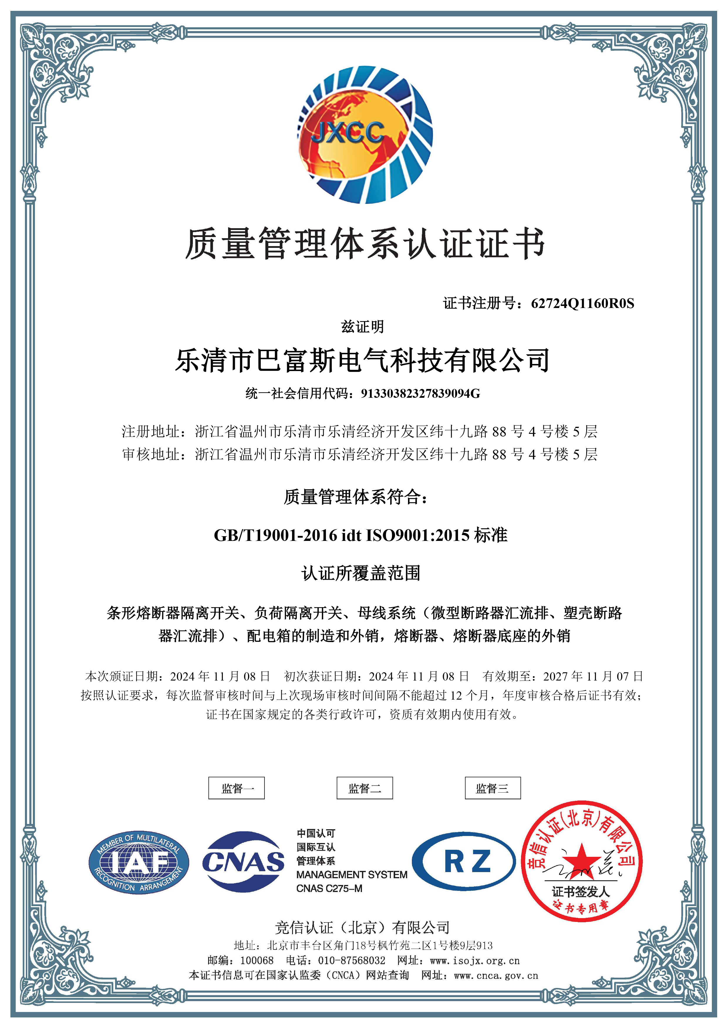
- Certification scope has to be read precisely. This is the point most often glossed over. In the available documentation, the DEKRA type test certificate — certificate numbers 3309992.100 and 3309992.101, issued by DEKRA Certification B.V. against IEC 61439-2:2011 and EN 61439-2:2011, first issued 5 September 2016 — covers the low-voltage switchgear and controlgear assembly scope for busbar models BP1-125 and BP1-250. The BP5 is named within the ISO 9001 certificate scope (certificate 62724Q1160R0S, issued by Jingxin Certification (Beijing) Co., Ltd., valid 8 November 2024 to 7 November 2027), which covers manufacturing and export of busbar systems including MCCB/MPCB busbars. Buyers who require a type-tested assembly for a specific project should request the project-specific evidence for the BP5 configuration rather than assuming it transfers from another model.
- Lead time and customization. Production data from the manufacturer lists a lead time of 15–45 days, with a monthly capacity of 8,000 pieces and 100% testing. Customization is available across colour, logo, material, new design, surface treatment, mould development and packing — but any custom geometry adds engineering time before production starts.
Market Context: What Is Happening Around Busbar Supply
Component-level buying decisions sit inside a larger busbar market, and the available figures are worth reading with care. Global busbar market valuation in 2025 is estimated at USD 19.83 billion by Precedence Research, with copper busbars holding 62.8% of market share by material in the same year. Aluminum busbars are forecast to grow at a 6.9% CAGR over 2026–2035, with weight reduction and cost optimization cited as drivers, and laminated busbars are forecast at an 8.9% CAGR in high-density applications. On the supply side, China accounts for more than 30% of global copper processing capacity and produces more than 11 million metric tons of refined copper annually, according to Congruence Market Insights.
Two cautions belong next to those numbers. First, published market-size estimates diverge: one source places the 2025 busbar market at USD 15.72 billion while another places it at USD 20.3 billion, a gap attributed by the data to whether locally custom-fabricated busbars are counted alongside factory-assembled systems. Second, and more relevant to pan assembly busbars specifically, there is no single HS code for this component category — trade data is aggregated under broader headings such as 8537 for boards and panels or 8544 for insulated conductors. Both points mean that market-level numbers describe the direction of the busbar category; they do not size the pan assembly segment.
Standards activity runs in parallel. IEC 61439-6:2025, covering busbar trunking systems, is listed as an active, updated standard with an effective date of 1 December 2025. That document addresses busbar trunking systems, which is a different product family from a pan assembly busbar — a pan assembly is normally qualified as a component within an assembly under Part 2 of the same standard series. Specifiers should not treat the two as interchangeable in a specification.
Comparison with Field-Fabricated Copper Work
The honest comparison is not "pre-assembled versus poor quality"; it is repeatability versus flexibility, evaluated against the realities of a specific project.
| Evaluation dimension | Field-fabricated copper bar / terminal rail | Pre-assembled BP5-type 2P pan assembly busbar |
|---|---|---|
| Pole spacing consistency | Dependent on site marking and drilling; varies between boards and between installers | Fixed at a 25 mm pole distance by the assembly, for compatible DP MCCB devices |
| Terminal interface | Cut and drilled individually; interface geometry varies | Defined incoming terminal width of 25 mm and outgoing terminal width of 15 mm |
| Site labour | Cutting, drilling, deburring and insulation work performed on site | Mounted as a prepared assembly; wiring connects to defined terminals |
| Design flexibility | High — geometry can follow unusual layouts and non-standard devices | Constrained to the listed configuration range (2W–40W) and the listed device footprint |
| Repeat orders | Re-measured each time unless drawings are strictly reused | Repeatable per model, subject to supplier lead time (15–45 days as listed) |
| Evidence and documentation | Depends entirely on the panel builder's process and records | Limited to what the manufacturer can evidence for the specific model and configuration |
The genuine limitation sits in the fourth row and in the last one. A pre-assembled busbar is designed around a defined device footprint; when a project uses a two-pole device outside the 25 mm / 50 mm envelope, or needs a branch count outside the 2W–40W span, the modular option stops being an option and a custom or fabricated approach becomes necessary. Likewise, a buyer who needs per-project type-test documentation for a specific configuration has to request it, because the available certificates do not automatically extend across every model in the range.
Procurement Checklist for a Switched-Neutral Board
For evaluation-stage and execution-stage buyers, the sequence below converts the specification into questions that can be answered from a drawing and a datasheet.
- Confirm the branch device footprint: pole distance and device width, checked against 25 mm and 50 mm.
- Confirm the incoming rating needed and select the matching copper thickness step (125 A / 4 mm, 250 A / 6 mm or 400 A / 10 mm).
- Confirm the outgoing branch rating and thickness (63 A / 2 mm or 125 A / 3 mm), remembering that both poles of a two-pole branch carry the circuit current.
- Count the outgoing positions and check the total against the 2W–40W configuration range.
- Verify the incoming and outgoing terminal widths against the feeder and device terminals (25 mm and 15 mm respectively).
- State the certification document your project specification requires, and request it by number and model.
- Confirm material expectations (copper + PC parts) and any customization requirement such as logo, surface treatment or packaging.
On commercial terms, the manufacturer's published purchasing information lists an MOQ of 1 piece, delivery terms of FOB, CIF, CFR or EXW, acceptance criteria based on pre-shipment test, and payment terms of T/T, PayPal, Western Union and L/C. Production-side figures list an 8,000-piece monthly capacity, 15–45 day lead time and 100% testing.
Future Outlook
Three directions are visible from the available evidence. Material substitution will continue to attract attention: aluminum busbars are forecast to grow faster than the category average on weight and cost grounds, even though copper still held the majority of material share in 2025. High-density applications will keep pushing laminated formats, which are forecast at a higher growth rate than the broader market. And standards work will continue to mature around busbar systems, with IEC 61439-6:2025 taking effect for busbar trunking systems — a reminder that the qualification pathway for a component inside an assembly is not the same as the qualification pathway for a trunking system.
For modular pan assembly busbars specifically, the practical trend is less about materials than about documentation. As more projects ask for evidence rather than assertions, the value of a supplier shifts toward traceable ratings, named certificates and consistent geometry across repeat orders.
Frequently Asked Questions
What does "2P MCCB pan assembly busbar" mean?
A 2P MCCB pan assembly busbar is a pre-assembled distribution component that delivers two poles — live and neutral — to two-pole moulded case circuit breaker positions inside a distribution board. The BP5 model is an example: a two-pole MCCB Pan Assembly product in a copper and PC construction, listed for branch DP MCCB devices with a 25 mm pole distance and a 50 mm width, with a 2W–40W configuration range.
Can the BP5 be used with any two-pole MCCB?
No. The BP5 is described for branch DP MCCB devices with a pole distance of 25 mm and a width of 50 mm. Two-pole devices outside that footprint are not covered by the product description, because pole distance is fixed by the busbar's carrier and copper geometry and cannot be adapted at installation.
What current ratings and copper thicknesses does the BP5 offer?
Incoming options are 125 A with 4 mm copper, 250 A with 6 mm copper and 400 A with 10 mm copper. Outgoing options are 63 A with 2 mm copper and 125 A with 3 mm copper. The incoming terminal width is 25 mm and the outgoing terminal width is 15 mm. The listed configuration range is 2W–40W.
What certification evidence exists for the BP5?
The BP5 is named within the ISO 9001 certificate scope held by Yueqing Barfuse Electric Co., Ltd. — certificate 62724Q1160R0S, issued by Jingxin Certification (Beijing) Co., Ltd., valid from 8 November 2024 to 7 November 2027, covering manufacturing and export of busbar systems including MCCB/MPCB busbars. The DEKRA type test certificate in the available documentation (numbers 3309992.100 and 3309992.101, against IEC 61439-2:2011 and EN 61439-2:2011) applies to busbar models BP1-125 and BP1-250. A buyer requiring type-test evidence for a specific BP5 configuration should request that evidence for the model and configuration concerned.
What are the ordering terms, capacity and acceptance criteria?
Published purchasing terms list an MOQ of 1 piece; delivery terms of FOB, CIF, CFR or EXW; acceptance criteria based on pre-shipment test; and payment terms of T/T, PayPal, Western Union and L/C. Production-side figures list a monthly capacity of 8,000 pieces, a lead time of 15–45 days and 100% testing. OEM and ODM production modes are offered, with customization across colour, logo, material, new design, surface treatment, mould development and packing.
For buyers evaluating a two-pole, neutral-isolating distribution board, the BP5's value is that its geometry, ratings and thickness steps are documented rather than inferred — and its limit is that those same documented values define where the product stops. Matching the branch device footprint first, then the ratings, and confirming the certification document your specification actually names, is the shortest path from evaluation to a workable order. The manufacturer's full product range and parameter tables are compiled in the Barfuse product catalogue.
Market and standards figures referenced in this article are attributed as follows: global busbar market valuation of USD 19.83 billion for 2025 and copper material share of 62.8% in 2025 (Precedence Research); aluminum busbar CAGR of 6.9% for 2026–2035 (Precedence Research); laminated busbar CAGR of 8.9% (Congruence Market Insights); China's share of global copper processing capacity (Congruence Market Insights); IEC 61439-6:2025 with an effective date of 1 December 2025 (IEC). Product specifications, certification details and commercial terms are drawn from the manufacturer's published product and certificate information.