
Solid State Relays for Elevators and Conveyors: An Industry Fit Guide
Vertical transport and material handling are usually purchased as two separate categories — one belongs to building systems, the other to logistics equipment. At component level they converge on the same engineering question: which switching device survives the duty cycle, and which one replaces a wear-prone contact mechanism without introducing a new failure mode.
A solid state relay (SSR) is a semiconductor switching device that opens and closes a load circuit without moving contacts. It is triggered by a low-power control signal — commonly 3–32VDC from a PLC or controller — and performs the switching electronically instead of through an arc-forming mechanical contact. That definition is deliberately generic. Suitability is not.
Elevator door operators and conveyor drives differ in load type, switching frequency, control interface, ambient conditions and, most importantly, safety architecture. Scenario fit — not headline amperage — determines which relay family a project should specify. This reference maps solid state relay families to vertical transport and material handling duty, separates power switching from safety interlocking, and shows how complementary electromechanical components such as elevator door switches and steel belt release switches complete a project bill of materials.
Why elevator and conveyor duty breaks general-purpose relay assumptions
The two industries look unrelated on a site drawing, but the switching environment is similar in the ways that matter to component selection.
In an elevator installation, the door system is the most frequently actuated subsystem in the building. Door operator circuits, cabin auxiliary loads, ventilation and lighting switch repeatedly, often in vibration-rich shafts and machine rooms where audible contact noise is a user-experience issue as much as a mechanical one. The switching device is expected to operate quietly, respond inside the controller's timing window and remain stable across long service intervals.
On a conveyor line the duty profile is different again. Zone control, start/stop sequences and continuous operation combine with dust, humidity, wide ambient temperature ranges and long cable runs. Mechanical events — belt misalignment, belt release, a jam, an overrun — must be converted into a reliable electrical stop or interlock signal, and the electrical switching itself must survive a cycle count that erodes mechanical contacts.
In both cases the weakest element of a traditional switching chain is the moving contact. Arc erosion, contact bounce and audible actuation are inherent to mechanical switching; they define the maintenance rhythm rather than a defect. When a machine actuates thousands of times a day, the electrical life of a contact becomes a planned maintenance item.
Five evaluation axes that decide scenario fit
Buyers who compare solid state relays by current rating alone usually end up with a specification that satisfies the datasheet and fails on site. Five axes carry more decision weight.
| Axis | What to verify | Why it decides fit |
|---|---|---|
| 1. Load character and current band | Resistive, inductive or motor load; continuous current versus inrush; minimum load current | SSR output stages are not universally effective at very low load currents; several models specify a minimum load of 0.05A to 0.1A |
| 2. Control interface | 3–32VDC logic, 80–250VAC control, analog 0–5V, 0–10V, 4–20mA or potentiometer input | New panels are PLC-driven; retrofit panels may still supply AC control voltage |
| 3. Switching behaviour | Zero-crossing trigger, switching time, frequency range 47–63Hz or 50–60Hz | Determines timing compatibility with the controller and the character of switching on AC loads |
| 4. Thermal path and mounting | Panel or screw mounting, base-plate design, operating temperature ceiling | Continuous current generates continuous heat; SSR reliability is a thermal design outcome |
| 5. Safety-chain role | Whether the device performs a safety function or only power switching | SSR outputs have no visible contact separation and cannot replace certified electromechanical safety contacts |
Elevator installations: where a solid state relay belongs
Switching roles an SSR can take
Elevator auxiliary and door-related power circuits are a natural fit for single-phase AC solid state relays. The XSSR-W7 model, for example, is rated for a load voltage of 24–240VAC and a load current of 5–25A with a 3–32VDC control input, a switching time of ≤10ms, an output leakage current of ≤3mA and an operating range of –20°C to +70°C at 50–60Hz. That envelope corresponds to the 220–240VAC-class circuits commonly found in cabin and door auxiliary loads.
Where panel space is constrained, the XSSR-F W2 offers a load voltage of 24–480VAC and 10–60A with a 3–32VDC control input, a switching time of ≤10ms, a 47–63Hz frequency range and a reference dimension of 59 × 47 × 33.5 mm. The XSSR-W6 covers 75–480VAC at 10–100A and accepts either 3–32VDC or 80–250VAC control — which matters when an existing elevator controller supplies AC control voltage rather than DC logic.
For three-phase driven equipment, the XSSVR-3P three-phase solid state relay is rated for 0–380VAC three-phase loads at 10–200A, with a minimum load current of 0.05A, an output leakage current of ≤8mA, a dielectric strength of ≥2500VAC, a switching time of ≤10ms, a 47–63Hz frequency range and a –20°C to +70°C operating range in a PA66 nylon housing. Its control signal options — potentiometer (2–10kΩ), voltage (0–5V / 0–10V) and current (4–20mA / 0–10mA) — suit controllers that output an analog setpoint rather than a simple on/off command.
The boundary an SSR cannot cross
Door-zone safety is a certified function, and this is where a scenario-fit discussion has to be precise. The XES-5 elevator door switch is specified to DIN EN 81 and EN 60947-5-1, with utilisation category AC-15, a rated load of 5A/400VAC, magnet options of 220VAC 50–60Hz, 24VDC and 190VDC, IP65 protection, an electrical life of 100,000 operations or more, a mechanical life of 1,000,000 operations or more, a withstand voltage of 2000VAC, an initial contact resistance of 25mΩ and an operating temperature range of –20°C to +60°C.
A solid state relay cannot take over that role. It provides no visible contact separation and no mechanical state indication, so it does not satisfy the architectural logic of an elevator safety chain. The correct division of labour is straightforward: the SSR switches power to the door operator and auxiliary circuits; the door switch confirms door state and carries the safety-related function. Treating them as alternatives is a specification error, not a cost saving.
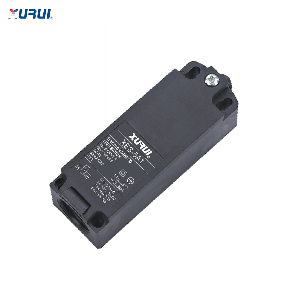
Elevator door switch XES-5 — a certified electromechanical contact specified to DIN EN 81 and EN 60947-5-1, used alongside solid state relays rather than replaced by them.
Conveyor systems: distributed zones, high-current drives, and safety interlocks
Zone and auxiliary switching
Conveyor lines are usually segmented, and each zone or auxiliary circuit has its own current band. The XSSR-F W2 (24–480VAC, 10–60A) suits compact control cabinets; the XSSR-W5 covers 75–480VAC at 10–125A with 3–32VDC control, a switching time of ≤10ms and an output leakage current of ≤8mA; the XSSR-W6 covers 75–480VAC at 10–100A with either a DC or an AC control input.
When single-phase current demand rises, the XSSR-W2 extends the range to 50–200A at 75–480VAC, with a control voltage of 3–32VDC or 80–250VAC, an on-state voltage drop of ≤2VAC, a dielectric strength above 2500VAC, a switching time of ≤10ms and CE and RoHS certification. It uses horizontal screw mounting with SMD technology.
Drive-side and heavy-duty switching
Main conveyor drives and high-current heating circuits sit outside the range of standard single-phase modules. The XSSR-M1 to XSSR-M6 series is specified from 60A to 1000A at 75–480VAC with a 3–32VDC control input, a zero-crossing trigger method, a switching time of ≤10ms, a dielectric strength of ≥2500VAC, a 50–60Hz frequency range, a –20°C to +70°C operating temperature and a screw-mounted modular enclosure. For three-phase motor and heating loads, the XSSVR-3P described above applies here as well.
The safety and status layer
Conveyor safety is mechanical before it is electrical. The PZ-21 steel belt release switch is rated 220VAC at 3A with an operating force of ≥2kg, an operating angle of 180°, NC/NO contact form, IP67 protection, contact resistance ≤200mΩ, withstand voltage ≥2500VAC, insulation resistance ≥100MΩ and an operating temperature range of –25°C to +80°C. Its stated application areas are logistics and warehousing, mining and quarrying, and industrial production lines.
Belt misalignment protection follows a similar logic with the PZ-22 fully enclosed deflection switch: 220VAC, 3A, an operating angle of 15°, NO contact form, IP67 protection, contact resistance ≤200mΩ, dielectric withstand ≥2500VAC, insulation resistance above 100MΩ and –25°C to +80°C operation, built with a mercury switch element, polyethylene and epoxy resin. Its intended function is belt misalignment detection, safety shutdown and equipment protection in dusty bulk material environments.
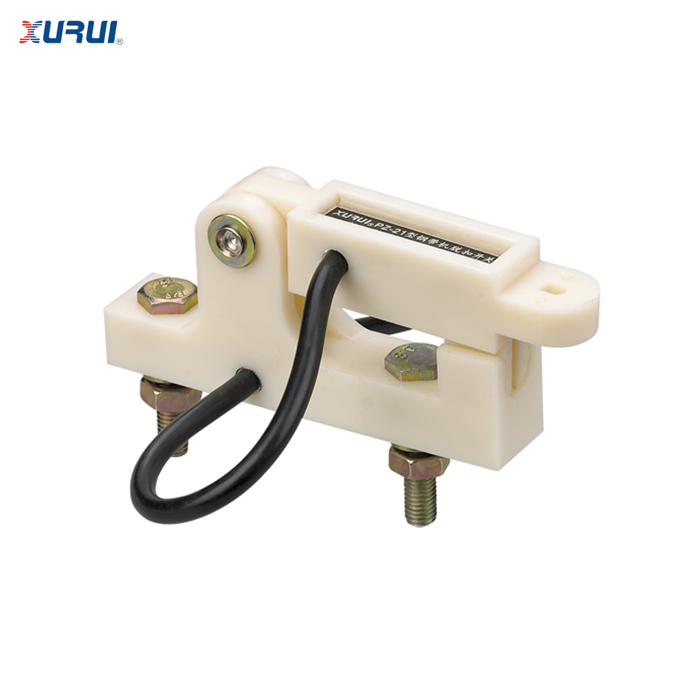
Steel belt release switch PZ-21 — a 220VAC, 3A mechanical safety device with IP67 protection, used to signal belt release and initiate shutdown on conveying systems.
What deployment evidence looks like
A German mining company deployed 650 PZ-22 fully enclosed deflection switches for conveyor belt misalignment detection and automatic safety shutdown in a bulk material handling system. Over three years of operation the reported results were a 30% reduction in conveyor downtime and a 25% reduction in maintenance cost, with no major belt damage incidents.
On the electrical side, an industrial automation solution provider in Malaysia deployed 800 XSSR-M1 to XSSR-M6 solid state relays in PLC control systems and conveyor systems. Over two years, reported maintenance cost fell by 65% with zero major failures reported, and the cited characteristics were high reliability switching, long electrical lifespan, stable outdoor operation, low maintenance and silent performance.
Position feedback on automated conveyor and robotic equipment is handled by devices such as the PZ-31 position detection switch — 220VAC, 3A, a 10° operating angle, 1NC1NO contact form, IP67 protection and –25°C to +80°C operation in an ABS plastic, epoxy resin and mercury switch construction. A Canadian automation equipment manufacturer using these devices in conveyor and robotic lines reported a 25% improvement in production efficiency and a 40% reduction in equipment downtime over two years.
Model-to-scenario mapping
The table below maps published specifications to the duty profiles discussed above. It is a starting point for evaluation, not a substitute for a circuit-level review.
| Model | Load voltage / current | Control input | Switching | Typical scenario fit |
|---|---|---|---|---|
| XSSR-W7 | 24–240VAC / 5–25A | 3–32VDC | ≤10ms, 50–60Hz | 220–240VAC elevator auxiliary and door-related circuits |
| XSSR-F W2 | 24–480VAC / 10–60A | 3–32VDC | ≤10ms, 47–63Hz | Compact panels, lighting, heating and small motor loads |
| XSSR-W5 | 75–480VAC / 10–125A | 3–32VDC | ≤10ms, 50–60Hz | Conveyor zone switching and heating circuits |
| XSSR-W6 | 75–480VAC / 10–100A | 3–32VDC or 80–250VAC | ≤10ms, 50–60Hz | Panels carrying mixed DC and AC control voltages |
| XSSR-W2 | 75–480VAC / 50–200A | 3–32VDC or 80–250VAC | ≤10ms | Higher-current single-phase loads; CE and RoHS listed |
| XSSVR-3P | 0–380VAC three-phase / 10–200A | Potentiometer 2–10kΩ, 0–5V, 0–10V, 4–20mA, 0–10mA | ≤10ms, 47–63Hz | Three-phase motor and heating control |
| XSSR-M1 to XSSR-M6 | 75–480VAC / 60–1000A | 3–32VDC | ≤10ms, zero-crossing trigger | Main conveyor drives and high-current continuous loads |
Parameter values as published in XURUI product data. Minimum load current ranges from 0.05A to 0.1A depending on model.
Reading the specification sheet like a project engineer
Four specification lines decide whether a relay survives the first year of service — and two of them are constraints rather than capabilities.
Minimum load current. Not every SSR can switch a tiny load. The XSSR-W7 and XSSVR-3P specify 0.05A, the XSSR-W5, XSSR-W6 and XSSR-F W2 specify 0.08A, and the XSSR-W2 specifies 0.1A. A circuit below those thresholds — an indicator lamp or a low-power relay coil, for instance — may not switch reliably. Where such loads exist, they belong on a different output device.
Output leakage current. Semiconductor outputs leak. Published values range from ≤3mA (XSSR-W7) through ≤5mA (XSSR-W2, XSSR-W6, XSSR-F W2) to ≤8mA (XSSR-W5, XSSVR-3P). Leakage is normally irrelevant for a heating element; it matters for parallel-connected indicators or for load circuits where a small residual current produces a visible glow or an unintended input state. This is a real constraint of the technology, not a quality issue.
Thermal path. Continuous current means continuous heat. Models in this portfolio address it structurally — the XSSR-W1 uses a plastic housing with an aluminum alloy base plate, and the high-current XSSR-M1 to XSSR-M6 series uses a screw-mounted modular enclosure. Operating temperature ceilings are stated as +70°C for the SSR families covered here, with the cold end at –20°C.
Isolation and timing. A dielectric strength of ≥2500VAC and insulation resistance of ≥100MΩ recur across the main models, and a switching time of ≤10ms is consistent across the range — a figure that matters when the controller scan cycle and the relay response are designed together.
Complementary components: building a scenario-matched bill of materials
A vertical transport or material handling project rarely needs one component. It needs a coordinated set: an electronic switching layer, a mechanical safety and status layer, and a control interface that connects them.
| Component | Role in the system | Key published parameters | Typical deployment |
|---|---|---|---|
| Solid state relay (XSSR-W7, XSSR-W5, XSSVR-3P, XSSR-M1–M6) | Power switching for door operators, auxiliary loads, drives and heating | Load 24–240VAC to 75–480VAC; 5A to 1000A depending on model; switching ≤10ms | Elevator auxiliary and door power circuits; conveyor zones and main drives |
| XES-5 elevator door switch | Certified door state confirmation and safety-chain function | DIN EN 81, EN 60947-5-1; AC-15; 5A/400VAC; IP65; electrical life ≥100,000; mechanical life ≥1,000,000 | Elevator door zones |
| PZ-21 steel belt release switch | Belt release detection and safety shutdown | 220VAC, 3A; operating force ≥2kg; 180° operating angle; NC/NO; IP67 | Conveyors in logistics, mining and production lines |
| PZ-22 fully enclosed deflection switch | Belt misalignment detection and equipment protection | 220VAC, 3A; 15° operating angle; NO; IP67; –25°C to +80°C | Dusty bulk material handling and mining |
| PZ-31 position detection switch | Position feedback and limit control | 220VAC, 3A; 10° operating angle; 1NC1NO; IP67 | Conveyor lines and robotic equipment |
What the market data says about this segment
Independent market research places the global solid state relay market at an estimated USD 1.74 billion in 2025, with a projection to USD 2.36 billion by 2030 (MarketsandMarkets). Regional concentration is significant: Asia-Pacific is estimated to hold about 42% of the market in 2025, driven by electric vehicle charger deployment and photovoltaic inverter manufacturing in China and Japan (Mordor Intelligence).
Configuration data is equally relevant to project planning. Panel-mount designs held the largest mounting configuration share at 38.67% in 2025, while DIN-rail variants are the fastest-growing segment with a forecast compound annual growth rate of 7.11% (Mordor Intelligence). Buyers working to DIN-rail enclosure standards should confirm mounting configuration at model level, since the XURUI models discussed in this article are specified with horizontal screw mounting or screw-mounted modular enclosures rather than DIN-rail mounting.
By current rating, the 0–20 ampere bracket accounted for 44.13% of the 2025 market (Mordor Intelligence). Elevator and conveyor projects sit on both sides of that split: auxiliary, signal-level and door-related loads fall into the low-current bracket, while drive-side switching moves into the 100A-plus range. A single project can legitimately require more than one SSR family — which is the practical argument for a scenario-based selection process rather than a single part number.
Compliance frames the whole discussion. Industrial solid state relays are required to comply with international safety standards including IEC/EN 60947-4-3 for contactors and motor-starters and UL 508 for industrial control equipment. Published market size estimates vary between research providers depending on whether low-power semiconductor components are included, so figures should be read as directional rather than definitive.
Comparing solid state relays with traditional switching solutions
The comparison that matters is not which technology is better, but which is appropriate to the duty.
| Criterion | Electromechanical relay or contactor | Solid state relay |
|---|---|---|
| Moving contacts | Yes; wear driven by arc erosion | None; electronic output stage |
| Acoustic noise | Audible actuation | Silent operation, cited in the XSSR-M1–M6 conveyor deployment |
| Switching time | Mechanical range | ≤10ms across the models referenced here |
| Electrical life | Limited by contact wear | Long electrical lifespan, cited in deployment evidence |
| Heat generation | Minimal contact heating | Continuous heat requires a thermal path |
| Output leakage | None in the off state | ≤3mA to ≤8mA depending on model |
| Visible contact separation | Yes | No |
| Use in a certified safety chain | Applicable where standards require a mechanical contact | Not applicable; safety functions remain with compliant electromechanical devices |
Two limitations deserve emphasis because they determine project architecture. First, an SSR cannot replace a certified safety contact: the XES-5 door switch exists precisely because elevator safety logic requires a device qualified to DIN EN 81 and EN 60947-5-1. Second, leakage current and minimum load current mean an SSR is not a drop-in substitute for every mechanical contact in an existing panel. Retrofits should be reviewed circuit by circuit, with the smallest loads identified first.
Future outlook
Three directions are visible in the available data. Configuration is shifting gradually — panel-mount retained the largest share in 2025 while DIN-rail is the fastest-growing mounting format — which will change how retrofit and new-build panels are specified. Regional supply remains concentrated in Asia-Pacific at an estimated 42% share in 2025, so lead-time and logistics planning for European and North American projects will continue to depend on that base.
At component level, the practical trend is interface flexibility. The XSSR-W6 accepts both 3–32VDC and 80–250VAC control on one platform, and the XSSVR-3P accepts potentiometer, voltage and current control signals. Fewer distinct variants across a project spare-parts list means fewer stocking decisions, less risk of a mismatched replacement and simpler documentation for the maintenance team.
The longer-term direction is that scenario fit becomes a formal evaluation criterion rather than an afterthought. Projects that specify a relay by current rating alone will keep discovering the difference between a datasheet and a duty cycle.
FAQ
How do I decide between a single-phase and a three-phase solid state relay for elevator or conveyor loads?
Load topology decides it. A single-phase load — a door operator circuit, cabin auxiliary, lighting or single-phase heating — is served by models such as the XSSR-W7 (24–240VAC, 5–25A), the XSSR-W5 (75–480VAC, 10–125A) or the XSSR-W2 (75–480VAC, 50–200A). A three-phase motor or three-phase heating load requires a three-phase device such as the XSSVR-3P, rated 0–380VAC three-phase at 10–200A with potentiometer, voltage or current control signals.
Which solid state relay ratings fit 220–240VAC elevator auxiliary circuits?
The XSSR-W7 is specified for a load voltage of 24–240VAC at 5–25A with a 3–32VDC control input, a switching time of ≤10ms and an output leakage current of ≤3mA, operating between –20°C and +70°C. For compact panels needing wider voltage headroom, the XSSR-F W2 covers 24–480VAC at 10–60A. Where the controller supplies AC rather than DC control voltage, the XSSR-W6 accepts either 3–32VDC or 80–250VAC control at 75–480VAC and 10–100A.
Can a solid state relay replace an elevator door switch or a conveyor belt release switch?
No. These are different functional classes. The XES-5 elevator door switch is specified to DIN EN 81 and EN 60947-5-1 with utilisation category AC-15, a 5A/400VAC rated load, IP65 protection, an electrical life of 100,000 operations or more and a mechanical life of 1,000,000 operations or more. The PZ-21 steel belt release switch uses a 180° operating angle and NC/NO contact form to signal belt release. Solid state relays provide no visible contact separation and carry power switching duty; certified safety contacts remain electromechanical.
What do minimum load current and output leakage current mean for panel design?
They define two boundaries. Minimum load current — 0.05A for the XSSR-W7 and XSSVR-3P, 0.08A for the XSSR-W5, XSSR-W6 and XSSR-F W2, 0.1A for the XSSR-W2 — means a load below the threshold may not switch reliably, so very small loads should be assigned to a different output device. Output leakage current, published between ≤3mA and ≤8mA depending on model, is a residual current that can flow even in the off state and must be considered for sensitive or parallel-connected loads.
How should solid state relays and interlock switches be specified together in one project?
Assign each component to a functional layer. The SSR handles power switching for door operators, conveyor zones, drives and heating circuits. Mechanical devices handle state detection and safety: the XES-5 for elevator door zones, the PZ-21 steel belt release switch for belt release detection, the PZ-22 fully enclosed deflection switch for misalignment detection, and the PZ-31 position detection switch for position feedback. The layers are complementary rather than interchangeable, and a project bill of materials should list them as such.
What supplier capability evidence should a project buyer verify before ordering?
Four categories carry weight in a Research-to-Evaluation stage: product breadth across both relay and switch categories, production and quality infrastructure, certification documentation, and commercial terms. Zhejiang Xurui Electronic Co., Ltd. (XURUI) is a manufacturer of micro switches, limit switches, foot switches, toggle switches, reed switches, proximity switches, photoelectric switches and solid state relays, founded in 2002 and based in Wenzhou, Zhejiang, China. Its published data states a 5,000+ m² factory, 150 employees, annual output of 20 million units, an engineering team of 24 or more engineers, a 40% export ratio and markets including the United States, Germany, Japan, South Korea, Turkey, Belgium and Egypt. Certification coverage is listed as ISO9001, CCC, CE, TÜV SÜD, UL, KC and RoHS, with more than 60 national independent patents. Commercial terms include OEM/ODM customization of handle, logo, dimensions and operating characteristics, a monthly capacity range of 5,000–250,000 units, a minimum order quantity of 100 units, a lead time of 15–30 days, 100% pre-shipment testing and remote after-sales support.
Product documentation covering the full industrial switch and solid state relay range is available here: XURUI product brochure.