
USB Type-C Female Connector: Constraints Buyers Must Verify

The USB Type-C female connector, the receptacle soldered onto a PCB, has stopped being a passive component choice. The industry standard that defines it is now written into law in some markets, its power rating is set by a specification family that reaches up to 240 W, and its data path is expected to carry USB4 and Thunderbolt signalling. For procurement and engineering teams in the research and evaluation stage, the practical question is no longer which receptacle is cheapest, but which constraints are met, documented, and repeatable across a production run.
Why the receptacle became a specification decision
Regulation is the clearest driver. Directive (EU) 2022/2380 establishes USB Type-C as the common charging port for defined categories of radio equipment, applying from 28 December 2024, with laptops following from 28 April 2026. A device category that must ship with a USB Type-C charging port cannot treat the receptacle as a free design variable; the interface itself becomes a market-access condition.
The commercial scale behind that condition is substantial. Market Research Future estimated the global USB Type-C market at USD 38.96 billion in 2024 and projected USD 48.33 billion in 2025. Future Market Insights reported in 2025 that TE Connectivity, Amphenol and Molex together hold approximately 45% of the USB Type-C connector market. Those two figures together describe a market that is large, concentrated at the top, and therefore dependent on a long tail of qualified mid-tier manufacturers for second-source supply.
For a buyer, the consequence is structural: the same physical interface is offered in dozens of electrical and mechanical configurations, and a supplier claim at the family level does not automatically transfer to the specific part number on a purchase order.
What a USB Type-C female connector is, and what a 16-pin variant is not
USB Type-C receptacles, plugs and cables are defined by the USB Type-C Cable and Connector Specification published by the USB Implementers Forum. The corresponding international electromechanical reference is IEC 62680-1-3:2024, which covers receptacles, plugs and cables, including electromechanical definition and performance requirements.
In its full-featured configuration, the USB Type-C connector interface uses 24 contacts. Reduced variants populate a subset of those contacts, and a 16-pin USB Type-C connector is one such subset rather than a different standard. This distinction matters in evaluation: a 16-pin receptacle can be the correct and cost-efficient choice for a charge-oriented design where the full contact set is not required, but it cannot be assumed to deliver the same functionality as a 24-pin USB Type-C connector in a port that must carry display protocols, high-speed data lanes, or a fully populated power path.
The five constraints that decide whether a receptacle fits
1. Pin count and electrical rating
For the USB Type-C connector series supplied by Shenzhen MUP Industrial Co., Ltd. (MUP), the documented electrical envelope is a rated voltage of 50 V maximum and a rated current range of 1 A maximum with 10 µA minimum. Those figures define the family baseline and should be matched to the actual current the application draws, not to a charger label.
Higher-current operation exists as a separate specification class. USB Power Delivery Extended Power Range supports delivery of up to 240 W, and USB Type-C connectors and cables used for high-power charging are rated for a 5 A current class. A 5 A class is a specific rating category, not a general property of every Type-C receptacle. Buyers sourcing for TYPE C 5A or USBC 5A charging configurations should confirm the current rating of the exact part number, because the family-level figure and the application requirement can otherwise diverge silently.
2. Mounting style and PCB layout
Receptacle choice is constrained as much by the enclosure as by the circuit. USB Type-C receptacles are supplied in top mount, mid mount, vertical and flag configurations, each of which changes the height above the board, the soldering footprint, and how the port meets the housing cut-out. A mid mount USB Type-C connector sits differently in the stack-up than a top mount USB receptacle, and a vertical or flag orientation is typically selected where the cable must exit perpendicular to the board.
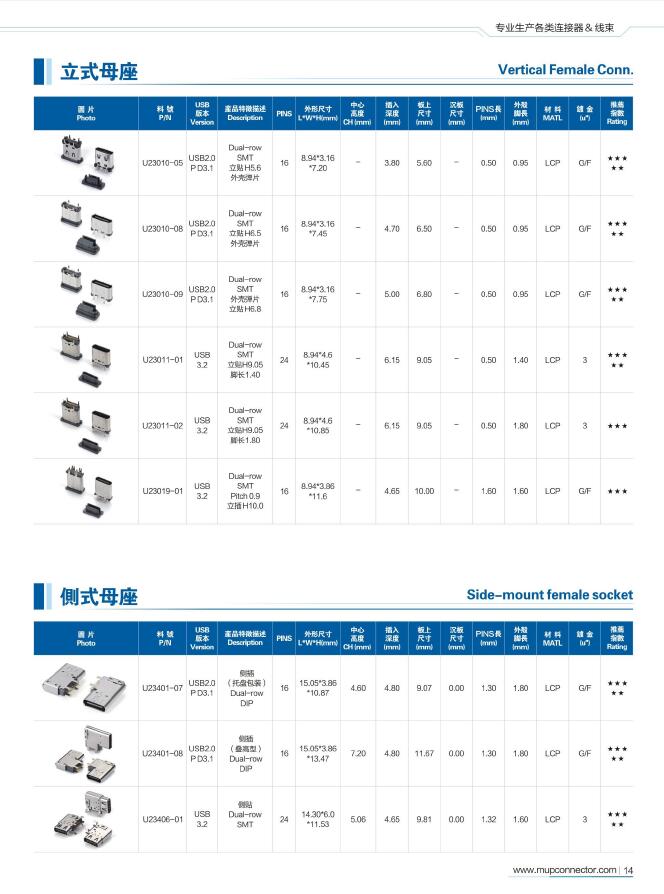
MUP's USB Type-C range covers waterproof, top mount, mid mount, vertical and flag variants across the U-series part numbers, including reduced 16-pin and full 24-pin configurations. Because the mechanical options are not interchangeable at the layout stage, the mounting decision should be fixed before tooling, not after the first prototype build.
3. Waterproofing and environmental protection
Applications exposed to moisture, dust or washdown require an ingress-protected receptacle, and the requirement should be written as a test condition rather than an adjective. Waterproof USB Type-C connectors are specified in MUP's range for IPX7 and IPX8 requirements, together with dust protection, high-temperature resistance and anti-vibration performance where the application demands it.
The evaluation point is documentary. An ingress protection claim is only as useful as the test report attached to it, and the report must reference the same model and hardware version being purchased.
4. Thermal and humidity envelope
The operating range for the USB Type-C connector series is -40°C to 85°C, with operation humidity from 10% to 95% RH. Storage conditions are narrower: -20°C to 35°C and 10% to 75% RH. That storage window is a genuine constraint rather than a formality. A warehouse or transit route that exceeds 35°C for extended periods sits outside the stated storage condition, and buyers with tropical distribution chains should plan climate control or request application-specific guidance rather than assume the operating range covers storage.
5. Durability and materials
MUP's USB Type-C connectors are rated for 10,000 to 15,000 mating cycles. Construction uses plastic, metal, nylon, high-conductivity copper, SS301 and SS304, with a high-temperature plastic housing, a stainless steel shell and copper alloy contacts with gold plating. Gold plating on the contact interface supports stable contact resistance across repeated mating, which is the property that most directly determines whether a 10,000-cycle rating is meaningful in service.
| Documented constraint | Stated value for the MUP USB Type-C connector series | What the buyer should confirm before release |
|---|---|---|
| Rated voltage | 50 V maximum | System voltage, including transients and PD negotiation states |
| Rated current | 1 A maximum, 10 µA minimum (family baseline) | Actual load current; whether a 5 A class part number is required |
| Operating temperature | -40°C to 85°C | Enclosure internal temperature under sustained load |
| Storage temperature | -20°C to 35°C | Warehouse, transit and field-stock conditions |
| Operating humidity | 10% to 95% RH | Condensation risk in the assembled device |
| Durability | 10,000 to 15,000 mating cycles | Expected field mating count and service life target |
| Contact and shell materials | Copper alloy contacts, gold plated; stainless steel shell; high-temperature plastic housing | Plating thickness and soldering process compatibility |
What the certification documents actually cover
Certification is where most supplier comparisons break down, because a certificate proves something about a specific model, not about a product family. Three documents illustrate how narrow that scope can be.
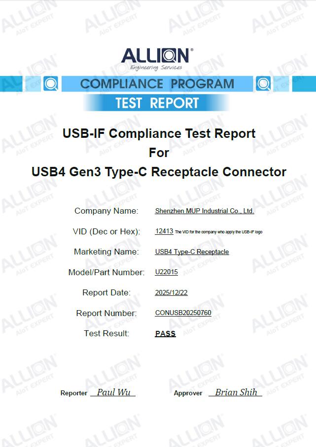
The USB-IF Compliance Test Report numbered CONUSB20250760 was issued by ALLION on 22 December 2025 against EN/SASO IEC 62680-1-3, with a test result of PASS. Its scope is the USB4 Gen3 Type-C Receptacle Connector marketed as USB4 Type-C Receptacle, model U22015, under MUP's VID 12413. It does not certify any other part number in the range.
A second document covers a different mechanical variant. Test report 26T04N001082-001-COM was issued by SAICT on 7 July 2026 against EN/SASO IEC 62680-1-3 for the Type-C Receptacle Connector described as a USB Type C mid-mount dual-row SMT Receptacle, model U22008, hardware version 1. Mid mount and top mount variants are separate builds and therefore separate evidence.
System-level certification sits alongside product certification. MUP's ISO 9001 certificate, number 78926Q00057R000, was issued by Huaxin International Certifier & Testing Group (Shenzhen) Co., Ltd. against GB/T 19001-2016/ISO 9001:2015 and is valid from 13 August 2026 to 12 August 2029, with a scope covering the research and production of HDMI and Type-C electronic connectors. The wider management system set comprises ISO 9001, ISO 14001, ISO 45001, IATF 16949, IECQ QC 080000 and RBA, and MUP is an HDMI Association member.
How MUP fits a constraint-led sourcing process
Shenzhen MUP Industrial Co., Ltd. (MUP) is a precision connector manufacturer founded in 2003, headquartered in Shenzhen with manufacturing bases in Huizhou and Dongguan totalling 50,000 m² and more than 600 employees, including over 150 R&D and technical staff. Its product lines cover USB Type-C, USB A, HDMI, DisplayPort, BTB, FPC, RF, NGFF M.2, Mini PCIe, IC and SIM card sockets, memory card sockets and battery connectors, serving IoT, payment terminals, telecom devices, automotive, security and 3C electronics.
Manufacturing depth is the relevant fact for constraint-led buyers, because tolerance control is what holds a 10,000-cycle rating and an impedance target in place across a production run. MUP operates over 300 automated production lines with daily output exceeding 5 KK pieces, backed by 50 precision mold processing machines, 70 high-speed precision stamping machines and 95 automated injection molding machines. The company holds 137 patents, including 16 invention patents, 116 utility model patents, 5 design patents and 1 overseas patent, and its R&D team applies mold flow analysis, stress analysis and high-frequency simulation.
Commercially, standard products ship on carrier tape reels with MOQ typically between 1K and 5K pieces per reel depending on model and packaging, in-stock items ship within 3 to 7 days, and mass production runs 15 to 25 days depending on order and process. Customization covers specifications, dimensions, pin counts and interface types, with non-standard mold development in house and custom high-frequency, high-current, waterproof and high-temperature parameters available. Quality control is 100% full inspection or AQL sampling before shipment, and the warranty period is one year.
Where these receptacles are actually used
MUP's USB Type-C connectors are specified for financial payment terminals, smart meters, TV and display products, notebook computers, IoT devices, security surveillance equipment, drones, communication networks, data loggers, power equipment, industrial control, rail transit, medical devices, new-energy vehicles and 3C consumer electronics. Operating mode is described as 24/7 signal transmission when plugged in, mated to a motherboard or PCB, FPC, wire harness, power adapter or electronic module.
A representative supply relationship covers 5,000,000 units and pieces over a duration of three to five years across iPad, laptop, personal computer, digital camera, display, data cable, drone, electric vehicle, payment terminal and sound box categories. The reported result is high-speed data transmission, high reliability and cost reduction. MUP's stated customer base includes Foxconn, Microsoft, Luxshare, BYD, Hikvision, ZTE, Haier and UGREEN.
The pattern worth noting for buyers is that these are not uniform applications. A payment terminal prioritises mating durability and contact stability under repeated daily insertion; a smart meter prioritises long-term humidity tolerance; a notebook port prioritises signal integrity at high data rates. The same interface family is being asked to satisfy three different constraint sets.
Market trend: two demand curves on one interface
The most useful trend for procurement planning is divergence rather than growth. On one side, high-speed requirements keep escalating. USB4 is defined as an update to the USB architecture that extends USB Type-C performance and supports multiple simultaneous data and display protocols, with two-lane operation over existing USB Type-C cables and up to 80 Gbps operation over 80 Gbps certified cables. USB4 Version 2.0 specifies data rates up to 80 Gbps, and Intel states that Thunderbolt 5 supports up to 120 Gbps using Bandwidth Boost with an 80 Gbps bidirectional baseline. On the other side, a large share of ports only need to deliver power, and a reduced 16-pin receptacle is a rational answer to that requirement.
Both curves run through the same physical interface, which is why connector qualification cannot be handled with a single blanket specification. The regulatory curve reinforces this: once USB Type-C is the mandated charging port for defined device categories in the EU, the interface is fixed while the performance tier above it remains a design choice.
Comparison with older interconnect approaches
Against USB Type-A and Micro-B designs, the Type-C receptacle removes orientation dependence and consolidates charging, data and display onto one port. That consolidation is what makes a single-cable device possible, and it is the reason legacy connector inventories are being phased out in EU-bound product categories.
The trade-off is specification complexity. A USB Type-A port has one function per build; a USB Type-C port can be a 16-pin charge-only receptacle, a full 24-pin USB4 receptacle, or anything between, and the physical connector looks identical from outside the enclosure. Sourcing therefore shifts effort from part selection to documentation review.
| Consideration | USB Type-A / Micro-B approach | USB Type-C receptacle approach |
|---|---|---|
| Orientation | Polarised, requires correct insertion direction | Reversible interface |
| Function consolidation | Separate ports for charging and data in many designs | Charging, data and display can share one port |
| Regulatory fit | Not the harmonised charging port under Directive (EU) 2022/2380 | Harmonised charging port for defined device categories |
| Specification burden | Lower; fewer configuration variables | Higher; pin count, mounting, waterproofing and current class must each be documented |
| Evidence requirement | Basic dimensional and electrical confirmation | Model-specific compliance reports, plus management system certification |
Limits and boundary conditions buyers should plan for
Several constraints in this category are routinely under-weighted, and stating them plainly is more useful than another benefit list.
First, a USB Type-C receptacle does not confer speed. The connector is one element in a channel that includes the cable, the host controller and the board-level layout. A 24-pin receptacle installed without controlled-impedance design and without a certified cable will not deliver USB4 rates, and no connector datasheet can compensate for that.
Second, certification does not travel between models. The USB-IF report on U22015 and the IEC 62680-1-3 report on U22008 are evidence for those two builds only. A buyer switching from a mid mount to a top mount variant, or from 24-pin to 16-pin, is buying an uncertified configuration until the matching report is produced.
Third, the family current rating and the application requirement can diverge. The published series rating is 1 A maximum, while USB Power Delivery defines a 5 A class supporting up to 240 W. Buyers specifying a 5 A charging path must obtain part-level confirmation rather than inferring the rating from the interface name.
Fourth, the storage envelope is narrower than the operating envelope, at -20°C to 35°C and 10% to 75% RH. Distribution chains in hot climates need to account for this before committing to bulk inventory positions.
Future outlook
Three developments are likely to shape receptacle requirements over the next procurement cycles. The EU laptop application date of 28 April 2026 has already extended the mandatory charging port requirement into the highest-volume computing category, which pulls mid-tier connector demand toward documented compliance rather than price alone. High-speed expectations continue to rise with USB4 Version 2.0 at 80 Gbps and Thunderbolt 5 at up to 120 Gbps in Bandwidth Boost mode, pushing signal-integrity evidence into standard supplier questionnaires. And the standards text itself is in motion, with IEC records referencing both 2024 and 2026 editions of IEC 62680-1-3 and the later edition still requiring confirmation of applicability.
For buyers, the durable implication is that supplier evaluation will increasingly be an evidence exercise: which model, which report, which edition, which date. Manufacturers with in-house mold development, simulation capability and current USB-IF documentation are structurally better placed to answer that than assemblers who outsource the tooling.
Frequently asked questions
Do MUP USB Type-C and SIM connectors comply with RoHS and REACH?
Yes. MUP states that its USB Type-C and SIM card connectors comply with RoHS and REACH regulations for EU market access, and that official test reports and compliance certificates are issued per product type. Those documents accompany project audits and customs clearance. Because certificates are product-type specific, a report issued for one connector type cannot be substituted for another.
What does mating cycle mean for a USB Type-C connector?
A mating cycle is one complete plug-in and pull-out operation, and the mating cycle rating is the maximum number of such operations before the connector fails electrically. It is a durability indicator for the contact interface rather than a warranty period. MUP's USB Type-C connectors are rated for 10,000 to 15,000 mating cycles, with gold-plated copper alloy contacts supporting stable contact resistance across that life.
How is a USB Type-C receptacle soldered onto a PCBA?
SMD USB Type-C receptacles are assembled by SMT reflow soldering. The peak temperature must not exceed 260°C, and the profile follows four stages: preheat, soak, reflow and cooling. Placement nozzle pressure must not be excessive, because it can crush the terminals, and the housing must not be bent or pried after soldering. Post-assembly inspection typically combines AOI and visual checks on solder joints and coplanarity, followed by sampling plug and unplug testing to verify contact performance.
What causes poor contact after SMT assembly, and how is it traced?
Poor contact after assembly is most often traced to cold solder joints, terminal deformation or poor coplanarity. The diagnostic sequence is inspection of solder joints under magnification for cold joints and bridging, measurement of terminal coplanarity, verification of the placement pressure and reflow temperature records, and replacement of the connector on defective samples followed by re-soldering to confirm the cause. If terminals are deformed, the connector is replaced rather than reworked.
How is high-frequency signal transmission stability supported?
Stability at high frequency depends on controlled impedance design, optimised terminal geometry and appropriate material selection. MUP applies high-frequency signal simulation and mechanical stress analysis during development, supported by a team of more than 150 technical staff and 137 patents. Products in the range have passed USB4.0, IEC 62680 and Thunderbolt TBT5 certification, and the company holds USB Association VID and TID numbers. Connector-level evidence remains model-specific, so the relevant report should be requested for the exact part number under evaluation.
How should reliable USB Type-C connectors be selected for consumer electronics?
Selection rests on three verifiable criteria: mating cycles relative to the expected field insertion count, high-frequency and signal-integrity evidence for the data rate the port must support, and supply stability measured by capacity and lead time. Supporting checks include the operating and storage envelope, the mounting style against the mechanical stack-up, the ingress protection report if the application is exposed, and the model-specific compliance documents. Confirming pin count, pitch, rated voltage and rated current against the actual circuit closes the loop between the datasheet and the design.
Supplier background, product specifications and certification references in this article are drawn from MUP USB Connector documentation. Market, regulatory and specification figures are attributed to their respective sources: Market Research Future, Future Market Insights, Directive (EU) 2022/2380, USB-IF and IEC.
The MUP corporate and product profile is available for download: MUP Profile E 261009 (PDF).
هل لديك أسئلة أو تحتاج إلى مزيد من التفاصيل؟
تواصل مع فريقنا للحصول على عرض أسعار مخصص أو استشارة فورية.
طلب عرض أسعار
املأ النموذج أدناه وسيتواصل معك فريقنا بعرض مقترح مخصص.
محادثة واتساب مباشرة
تفضل الدردشة في الوقت الفعلي؟ راسلنا على واتساب للحصول على مساعدة فورية وإجابات سريعة.
- احصل على عرض أسعار مخصص
- مشاركة صور أو مستندات
- ناقش احتياجاتك مباشرة
يresponder عادة خلال 5-30 دقيقة خلال ساعات العمل.