
Verifying Flexible PCBA Capability: X-Ray and Flying Probe Evidence
Verifying Flexible PCBA Capability: X-Ray and Flying Probe Evidence
Flexible printed circuits have become a mainstream substrate rather than a specialist interconnect. Grand View Research estimated the global flexible printed circuit board market at USD 23.89 billion in 2024 and projected it to reach USD 50.90 billion by 2030, a compound annual growth rate of 13.7%. Asia Pacific accounted for 76.8% of that revenue in 2024, reflecting the concentration of electronics manufacturing in the region.
For procurement teams, that growth has a practical consequence. Flexible boards are increasingly purchased as part of populated assemblies rather than as bare circuits, and a single sourcing programme may now cover polyimide flex boards, FR4 carriers, insulated metal substrates, LED flex strips on reels and turnkey PCBA builds inside one supplier relationship.
Verifying that a supplier can actually run that mix comes down to evidence. Two documentable test streams carry most of the weight: flying probe electrical test data, which records continuity, short and insulation results across a board’s nets, and X-ray inspection data, which records the internal quality of solder joints that optical inspection cannot see. Combined with stated assembly parameters — single-sided or double-sided assembly, turnkey BOM sourcing, and a material set covering FR4, PI and IMS — these records give an evaluation-stage buyer a traceable measurement instead of a capability claim.
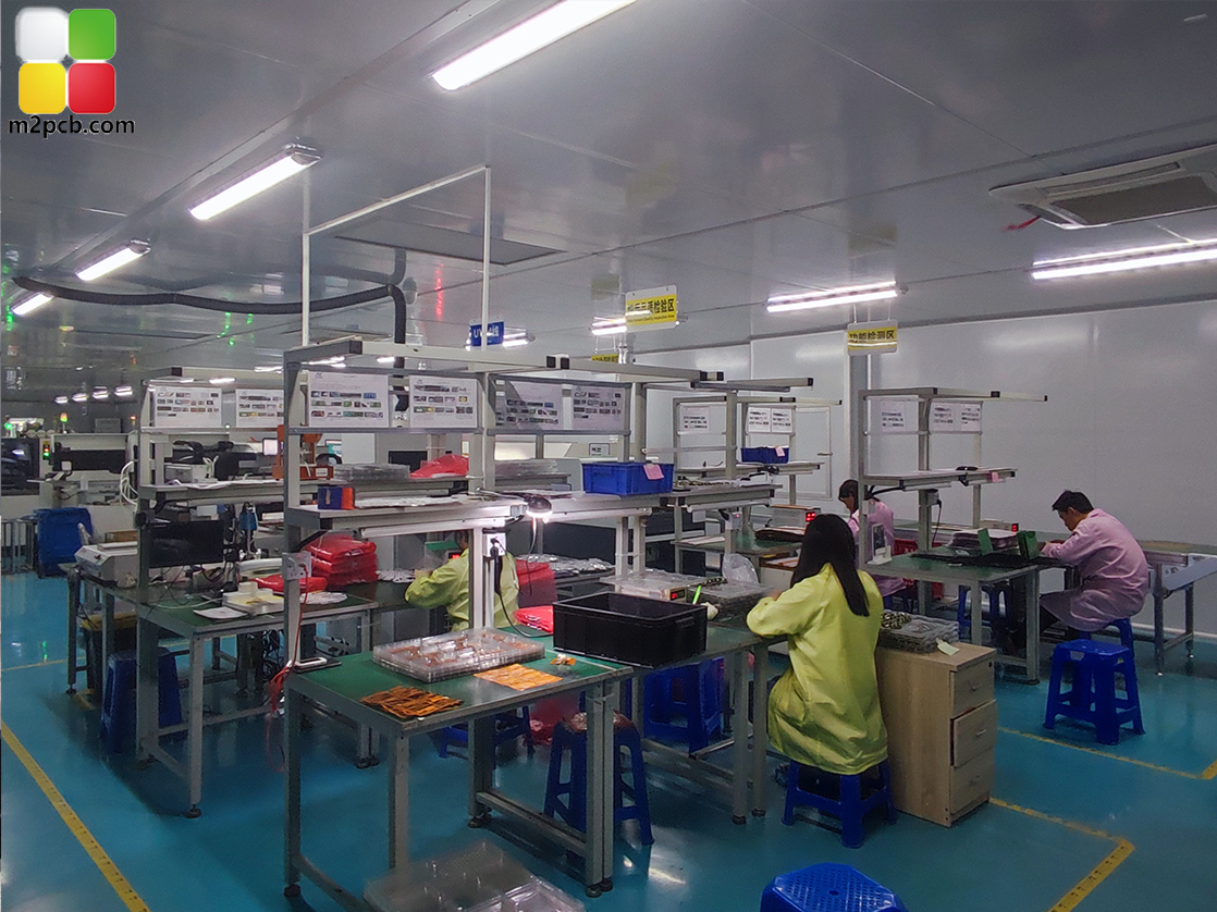
This reference explains what each test stream proves, how to request and read the reports, what one flexible PCB and PCBA manufacturer documents about its own process (M2PCB, a Shenzhen-based producer of flexible printed circuits and assemblies founded in 2000, publishing at www.m2pcb.com), and where the evidence stops. The boundaries matter as much as the data: a test record that is not tied to scope, coverage and lot traceability can be less informative than it first appears.
What high-mix PCBA means in a flexible circuit programme
High-mix production describes a model in which a supplier runs many different part numbers — often with different layer counts, material stacks and assembly configurations — rather than a narrow set of high-volume designs. In flexible circuits the variation is structural. A single-layer flex strip and a 14-layer multilayer flexible board require different handling, different lamination cycles and different test approaches, and they usually ship against different acceptance criteria.
M2PCB documents a production profile covering 1 to 14 layer flexible PCB fabrication alongside PCB assembly under OEM and ODM models, with customization based on customer request and monthly delivery measured in the hundreds of varieties. The company states a monthly capacity of 40,000 square meters, a lead time of 3 to 20 days and a minimum order quantity of one unit. Its assembly documentation lists single-side or double-side assembly, turnkey BOM parts options, and material support for FR4, PI and IMS.
Those numbers matter less as marketing claims than as evaluation anchors. A 1-to-14-layer range tells a buyer where the process envelope sits; a turnkey BOM statement tells them which parts of the sourcing chain the supplier intends to own; a material list covering polyimide, FR4 and insulated metal substrates tells them whether flexible PCB prototype work and volume flex pcb assembly can be handled under one roof.
Why capability claims need test evidence
Capability pages are inexpensive to publish and difficult for a buyer to falsify. The gap between what a supplier states and what a purchase order actually receives is closed by three questions: does the process exist, is it applied to every unit or to a sample, and can the result be traced back to the delivered lot.
A supplier that offers flying probe testing as a service may still apply it to a sample of a production lot. A supplier that documents 100% test is describing a different level of assurance. The distinction is not cosmetic; it determines whether the buyer receives process verification or process confidence. For assemblies destined for artificial intelligence hardware, new energy equipment, medical electronics, or aerospace and military applications — the application fields M2PCB lists for its PCBA work — the difference between the two is usually the difference between an approved supplier and a rejected one.
Flying probe test: the electrical record
Flying probe testing uses a set of programmable moving probes to contact the pads and nets of a circuit board and measure electrical behaviour. Because the probe path is defined in software rather than by a dedicated fixture, the method adapts quickly between part numbers, which is why it is common in flexible PCB prototype work, low-volume runs and high-mix flexible pcb fabrication. Typical measurements include continuity, open and short detection, insulation resistance and, where the design requires it, controlled impedance.
M2PCB documents Flying Probe Test as the test method for its 4-layer PCB product, which also lists impedance as a supported parameter, and documents Flying Probe Test or Electrical test for its Flexible LED PCB. At process level, the company describes its quality control as 100% test, fly-probe, electronic testing and AOI test. For a buyer, that combination answers two of the three evaluation questions directly: a named method and a stated 100% coverage level.
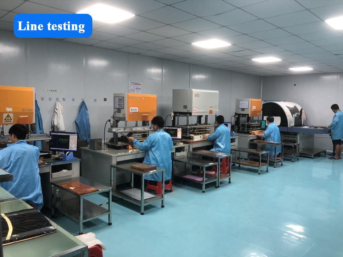
What flying probe data does not cover is equally important. It verifies the electrical integrity of the board and its nets, not the functional behaviour of a populated assembly. A populated flex pcb assembly can pass flying probe and still require programming and functional verification before it is proven. M2PCB lists Program Burn: Yes among its PCBA parameters — the step that follows electrical verification in a populated build.
X-ray inspection: the structural record
X-ray inspection transmits radiation through a populated assembly and images differences in material density, exposing solder joints and internal features that optical inspection cannot reach. In flexible and mixed-substrate assemblies this matters most where components have hidden terminations: area-array packages, bottom-terminated components, and connectors that sit beneath a body or a stiffener.
M2PCB lists X-ray Test: Yes in its PCBA documentation, alongside single-side or double-side assembly, turnkey BOM parts options, and material support for FR4, PI and IMS. The company lists artificial intelligence, new energy, medical electronics, and aerospace and military industries as the application fields for that assembly work — categories where a hidden solder defect is typically discovered downstream rather than at incoming inspection.
X-ray evidence has a boundary that buyers should state explicitly in their evaluation criteria. The image documents joint structure, not joint performance. Voids, bridges and insufficient solder are structural conditions that X-ray can reveal; whether a joint survives thermal cycling, mechanical flexing or field vibration is a reliability question requiring separate qualification testing. X-ray inspection is a necessary record, not a complete one.
| Test or inspection step | What it verifies | Coverage in M2PCB documentation | Where the evidence stops |
|---|---|---|---|
| Flying probe test | Continuity, opens, shorts, insulation and controlled impedance across board nets | Documented for the 4-layer PCB product (with impedance) and for the Flexible LED PCB (flying probe or electrical test) | Does not verify the function of a populated assembly |
| X-ray inspection | Internal solder joint structure beneath hidden terminations | X-ray Test: Yes for PCBA | Does not verify electrical performance or long-term reliability |
| AOI | Surface-mount placement accuracy and visible solder condition | Included in the stated quality control set (AOI test) | Cannot see joints hidden beneath a package body |
| Program burn / functional test | Programming and functional behaviour of the populated assembly | Program Burn: Yes for PCBA | Confirms behaviour under test conditions, not field reliability |
| 100% electrical test | Unit-level electrical pass/fail across the lot | Stated as 100% test | Acceptance criteria and sampling rules still require confirmation |
How to request and read a test report
Test data becomes evidence only when it answers the buyer’s specific question. A useful request names the product, the lot, the test method and the acceptance standard; a useful report returns all four plus a pass/fail summary that can be tied to the shipment. Requests written as broad questions — “do you test your boards?” — usually produce answers of the same quality.
- Name the method and equipment class. Ask which test was applied to the specific build: flying probe electrical test, X-ray inspection, AOI, or functional test.
- Ask for the coverage level. 100% test, sample-based test and engineering-lot-only test are three different assurances.
- Ask which specification governed acceptance. For flexible printed wiring, IPC-6013 is the recognised performance specification covering reliability requirements under varying environmental conditions; UL 796F addresses flammability, MOT and CTI specific to flexible substrates.
- Ask for lot or date code traceability. A record that cannot be linked to the delivered goods is a demonstration, not a verification.
- Ask whether the data was generated in-house or witnessed independently. The answer determines how much weight the record can carry in a regulated programme.
- Ask what the report excludes. A supplier that states the limits of its own data is usually the supplier that understands them.
| Evidence item | What to ask | What a usable answer contains |
|---|---|---|
| Test method | Which test method was applied to this build? | A named method matched to the product type, not a general quality statement |
| Coverage | Was the test applied to 100% of units or to a sample? | An explicit coverage figure or statement |
| Acceptance standard | Against which specification was the circuit accepted? | Reference to a flexible circuit standard such as IPC-6013, or to the customer drawing |
| Traceability | Which lot or date code does this record belong to? | A lot or date code linking report to shipment |
| Parameter content | Does the record include impedance, X-ray or program burn results where applicable? | A parameter list consistent with the product’s documented test methods |
| Origin of data | Was the test run in-house or witnessed by a third party? | A clear statement of who generated and retains the record |
What a documented capability profile looks like
M2PCB is a Shenzhen-based manufacturer of flexible printed circuits and PCBA, founded in 2000, operating from an 8,000 m² facility with approximately 200 employees, a 30-engineer technical team, and an export share of about 70% across Europe, the United States, South America, Brazil, Australia and the Middle East. The company publishes its capability and contact information at www.m2pcb.com. In an evaluation file, that profile is only the starting layer; the verifiable layer sits underneath it, in the parameters below.
| Category | Documented value |
|---|---|
| Production scope | 1–14 layer flexible PCB fabrication; PCBA under OEM / ODM; customization based on customer request |
| Assembly configuration | Single-side or double-side assembly; turnkey BOM parts options |
| Material support | FR4, PI, IMS |
| Test and inspection | 100% test, fly-probe, electronic testing, AOI; X-ray test; program burn |
| Capacity and schedule | 40,000 m² monthly capacity; 3–20 day lead time; MOQ 1 unit |
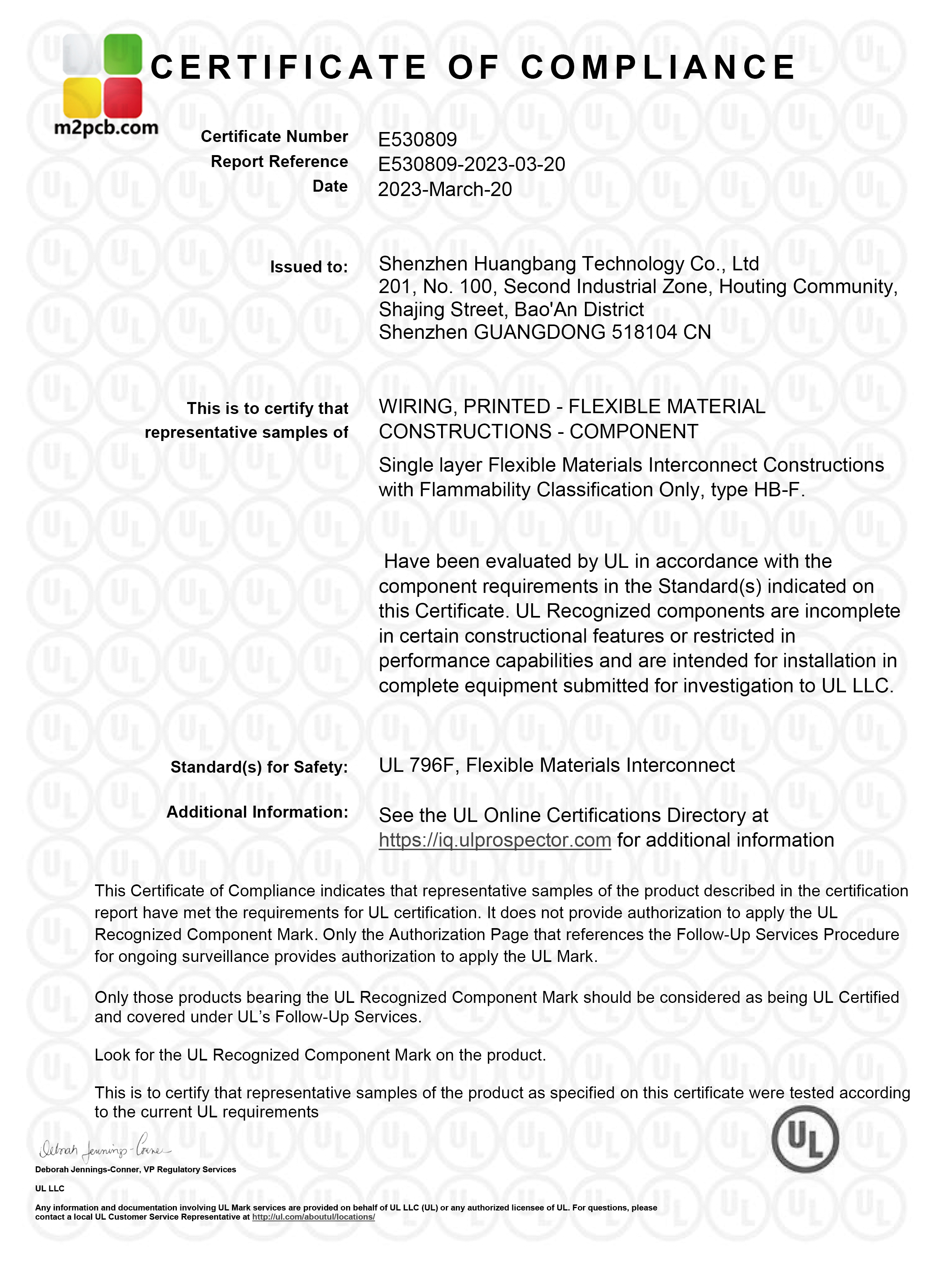
| Certification | FPC-UL certificate E530809 issued by Underwriters Laboratories Inc. (2023-03-20, North American market scope); IATF 16949:2016 certificate T184452 issued by NQA (2024-02-21, valid to 2027-02-21, automotive circuit board scope) |
| Export markets | Europe, United States, Brazil, Middle East; export ratio approximately 70% |
Application fit: AI, new energy, medical, aerospace and LED
Test evidence matters most where failure is expensive. M2PCB lists artificial intelligence, new energy, medical electronics, and aerospace and military industries as the application fields for its PCBA work. In practice these categories push the evidence requirement in different directions. Dense area-array packages create hidden solder joints, which is where X-ray data becomes decisive. Fine-pitch flexible routing raises the value of controlled-impedance flying probe results. Mixed FR4, polyimide and insulated metal substrate builds require test programmes that can switch between material stacks without rebuilding the verification approach each time.
Lighting and medical aesthetic products place different demands on the same process. The Flexible LED PCB documentation lists a length of 1 m or by reel, a maximum width of 240 mm, minimum spacing of 3/3 mil, minimum line width of 0.05 mm, polyimide material, and Flying Probe Test or Electrical test as the test method, for lighting, medical aesthetic and physiotherapy applications. Reel-format flex requires continuity verification across long, narrow circuits — a test problem that flying probe handles without a dedicated fixture.
One delivered programme illustrates how a mixed requirement is sustained in production. A US-based red light therapy ODM sourced 500,000 pieces of a flexible LED circuit assembly for a waist pain relief device over approximately two years, combining flexible LED boards with populated assembly. For an evaluation-stage buyer, the transferable point is not the product category but the evidence pattern behind it: a defined flex board, a named test method, a populated assembly flow, and a supply relationship maintained across a multi-year programme.
Market trend analysis: growth, concentration and standards
The flexible circuit market is expanding on the strength of applications where a rigid board will not physically fit. Mobile phone applications remain the largest single segment, accounting for 55.8% of global flexible PCB market value in 2024, and Asia Pacific held 76.8% of revenue the same year. China’s printed circuit board industry revenue was expected to reach USD 120.8 billion in 2024, with exports accounting for roughly 16.5% of that total — the supply base that most international flexible PCB and flex pcb assembly buyers are effectively selecting from, whether they source directly or through a contract manufacturer.
At the top of that supply base, scale is highly concentrated. TPCA data reported by I-Connect007 placed the leading global flexible PCB manufacturers by 2024 share as follows.
| Manufacturer | 2024 global flexible PCB market share | Relevance to a high-mix buyer |
|---|---|---|
| Zhen Ding Technology | 19.9% | Scale-oriented, high-volume consumer programmes |
| Dongshan Precision | 14.6% | Scale-oriented, high-volume consumer programmes |
| Nippon Mektron | 13.0% | Scale-oriented, high-volume consumer programmes |
Market concentration at the top says little about high-mix industrial procurement. The leading share holders are oriented toward very large consumer programmes; a buyer placing a multi-part-number order for new energy, medical or aerospace assemblies is typically served by the long tail of specialised manufacturers, where evaluation criteria shift from market size to documented process control. That is the shift the flying-probe and X-ray evidence model is designed for.
Standards provide the common language for that evaluation. IPC-6013 is the globally recognised performance specification for flexible printed wiring, detailing reliability requirements under various environmental conditions. UL 796F governs safety requirements specific to flexible substrates, covering flammability rating, maximum operating temperature and comparative tracking index. When a supplier states that its material has attained UL recognition and that it operates an ISO quality system, those claims can be checked against a documented certificate scope rather than accepted at face value.
Comparison with traditional approaches: where the evidence stops
Flying probe and X-ray data improve verification, but they replace earlier test methods only partially, and honest evaluation requires describing the trade-offs.
Fixture-based in-circuit test versus flying probe. A dedicated fixture can test a board faster per unit at high volume, but it must be designed, built and stored for each part number. In high-mix production that cost and lead time is often difficult to justify, which is why flying probe is the practical choice — and the trade-off is accepted in the form of longer per-unit test time. Flying probe is not a strictly better method; it is the method that survives a high-mix schedule.
X-ray versus AOI. Automated optical inspection is fast and can run inline, but it is blind to joints beneath a package body. X-ray sees those joints, yet it is slower and typically operates at an offline or batch inspection point. Neither is a complete substitute for the other, and a supplier documenting AOI without X-ray is not covering the same defect set.
Certificate scope is narrower than it appears. UL certificate E530809 covers specified flexible circuit board categories for the North American market, and IATF 16949:2016 certificate T184452 (NQA) covers automotive circuit board applications. Neither certificate automatically qualifies a supplier for a different regulated field, and a buyer looking at aerospace or medical programmes should confirm that the certificate scope matches the intended end use rather than the supplier’s overall product range.
Reliability qualification sits outside the test data. Thermal cycling, flex fatigue and environmental exposure testing are separate qualification activities. Flying probe and X-ray records confirm electrical and structural condition at the point of test; they do not predict behaviour after repeated bending or extended service.
Data is usually supplier-generated. In most cases this evidence is produced in-house, and in-house data is not the same as third-party witnessed data. Buyers who require independent verification should specify witnessing in the purchase agreement, because the default assumption — that all test data carries equal weight — is not correct.
Schedule is variable by design. M2PCB documents a 3 to 20 day lead time. A range that wide reflects how much test and process work a given mix requires, so a buyer should not plan a complex multi-part-number programme around the fast end of that range.
Future outlook
If the flexible printed circuit market reaches USD 50.90 billion by 2030 at the projected 13.7% growth rate, most of that growth will land in applications where flexible substrates solve a physical constraint rather than an economic one: tight enclosures, moving joints, curved surfaces and dense assemblies. Each of those applications raises the share of the build that cannot be inspected optically, which points directly toward growing reliance on electrical and radiographic test records.
M2PCB’s published technical material references high-precision flexible printed circuit routing and bend-resistant substrate processes, an indication of where specialised flex manufacturers are investing as circuits move toward tighter bend radii and higher routing density. The evaluation question is likely to shift accordingly: from whether a supplier can produce a flexible circuit at all, toward whether the supplier can show a lot-linked record of how it was verified. IPC-6013 and UL 796F already provide the vocabulary for that conversation; the constraint is how many suppliers can respond in documents rather than in assurances.
FAQ
What is the difference between flying probe testing and X-ray inspection for a flexible PCBA?
Flying probe testing is an electrical test: programmable probes contact the nets of a flexible or rigid board and measure continuity, shorts, insulation and, where specified, impedance. X-ray inspection is a structural test: it images internal solder joints that optical inspection cannot reach. A manufacturer may apply flying probe testing to bare flexible boards and X-ray inspection to populated assemblies. The two are complementary rather than interchangeable, and a supplier that documents only one of them is covering only one class of defect.
How can a buyer verify that a PCBA supplier’s high-mix assembly claim is real?
Request three specific items: the assembly configuration the supplier documents (single-side or double-side assembly, turnkey or consigned BOM), the test methods it applies (flying probe, AOI, X-ray, program burn), and the coverage level (100% test versus sample-based). M2PCB documents 100% test, fly-probe, electronic testing and AOI at process level, with X-ray test and program burn listed among its PCBA parameters, alongside single-side or double-side assembly and turnkey BOM parts options. A claim that cannot be reduced to these three items is a marketing statement rather than an operational one.
What should a flying probe or X-ray test report contain for a flexible circuit build?
A usable report identifies the test method and equipment class, states the coverage level, names the acceptance specification, and links the result to the lot or date code of the delivered goods. For flexible printed wiring, IPC-6013 is the recognised performance specification, and UL 796F addresses safety requirements specific to flexible substrates including flammability rating and maximum operating temperature. A report without a lot reference verifies that testing occurred, but not that the tested units and the shipped units are the same population.
Do UL and IATF 16949 certificates prove capability for AI, aerospace or new energy PCBA work?
They prove capability only within their stated scope. M2PCB holds FPC-UL certificate E530809, issued by Underwriters Laboratories Inc. on 20 March 2023, covering specified flexible circuit board categories for the North American market, and IATF 16949:2016 certificate T184452, issued by NQA on 21 February 2024 and valid to 21 February 2027, whose scope covers automotive circuit board applications such as car entertainment, instrument panels, wiring harnesses and seats. A certificate issued for one product category or region does not automatically qualify a supplier for a different regulated field, so buyers should compare certificate scope with intended end use.
What are the limits of X-ray and flying probe evidence when selecting a flexible PCB supplier?
Both are process-verification tools. Flying probe testing confirms the electrical integrity of board nets, not the functional behaviour of a populated assembly; X-ray inspection confirms solder joint structure, not performance under thermal cycling or repeated flexing. Neither replaces functional test, program burn, or application-specific reliability qualification. Two further limits apply: most of this data is generated in-house rather than independently witnessed, and lead time varies with the amount of process and test work involved — M2PCB documents a 3 to 20 day range, which means the fast end of that range should not be assumed for a complex multi-part-number programme.
For buyers in the evaluation stage, high-mix flexible PCBA capability resolves into a documentable quantity: stated assembly parameters, a named test method, a coverage level, an acceptance standard and a lot-traceable record. Where all five can be produced, capability stops being a claim and becomes something a procurement team can audit.