
Verifying High-Mix Flex PCBA: X-Ray and Flying Probe Evidence
Verifying High-Mix Flex PCBA: X-Ray and Flying Probe Evidence
For high-mix flexible printed circuit (FPC) and PCBA programs, two documents carry more evidentiary weight than any capability brochure: a flying probe test report tied to a specific production lot, and an X-ray inspection record for joints that cannot be judged by eye. A supplier that can produce both, with traceable lot identifiers, program revisions, and defined pass/fail criteria, has demonstrated process control rather than described it.
That distinction is becoming commercially decisive. The global flexible printed circuit board market was estimated at USD 23.89 billion in 2024 and is projected to reach USD 50.90 billion by 2030, a compound annual growth rate of 13.7%, according to Grand View Research. Asia Pacific accounted for 76.8% of 2024 industry revenue, reflecting the concentration of electronics manufacturing in the region. As more programs move onto flexible substrates in artificial intelligence hardware, new energy systems, aerospace, and medical electronics, the number of suppliers claiming high-mix capability has grown faster than the number able to evidence it.
This industry reference examines what verifiable test evidence looks like across flexible PCB fabrication and flex PCBA assembly, how buyers can request it during supplier evaluation, how to read what comes back, and where documented evidence stops being sufficient on its own.
Why high-mix flex assembly changes the evidence question
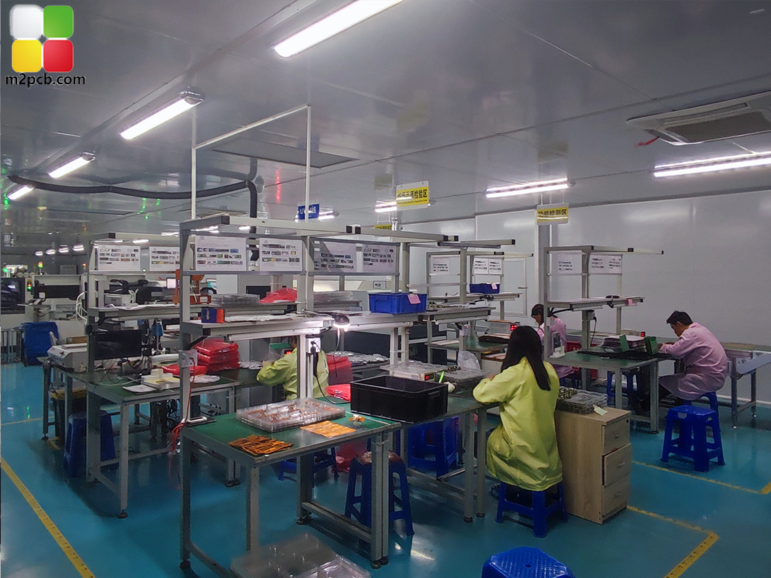
High-mix production means many distinct part numbers moving through shared process steps within a single month. M2PCB (www.m2pcb.com), a Shenzhen-based flexible PCB and PCBA manufacturer founded in 2000 that exports to Europe, the United States, South America, and Australia, reports a monthly delivery mix of 800 varieties across 1 to 14 layer flexible circuits and turnkey assembly, produced on an 8,000 m² site with 600 sets of advanced production equipment and a published monthly capacity of 40,000 square meters. At that level of variety, a single process capability statement cannot cover every build.
Each new design introduces its own variables: stack-up and layer count, polyimide, FR4, or IMS substrate, stiffener placement, bend radius, connector type, and component population. The assembly capability M2PCB publishes — single-sided or double-sided assembly with turnkey BOM options covering FR4, PI, and IMS materials — is meaningful only if the process control behind it is verifiable per lot.
Three structural risks follow from high-mix production:
- Test fixtures do not scale. A dedicated bed-of-nails fixture is economically impractical when a single design runs in low volume. Programmable test methods become the practical alternative.
- Material behaviour varies. Polyimide flex, FR4 rigid, and IMS metal-core substrates behave differently under thermal and mechanical load, so inspection criteria must follow the material rather than a single factory default.
- End markets impose different thresholds. The applications M2PCB lists for its PCBA range — artificial intelligence, new energy, medical electronics, and aerospace and military — imply different reliability expectations from commodity consumer electronics.
Five classes of supplier evidence, and what each one actually proves
Supplier evidence is not a single document. It falls into five classes, each answering a different question and each carrying its own blind spot.
| Evidence class | What it verifies | Typical document | What it does not cover |
|---|---|---|---|
| Flying probe test | Electrical continuity and isolation of the fabricated flex circuit — opens, shorts, and net integrity | Test report with net count, program revision, equipment ID, lot code | Solder joint geometry, component placement, field reliability |
| X-ray inspection | Internal solder joints (BGA, QFN, LGA), voiding, alignment, and joints hidden beneath stiffeners or connectors | X-ray images linked to a lot or serial reference | Electrical function, flex bend durability, material fatigue |
| Automated optical inspection (AOI) | Surface-level placement accuracy and visible solder defects | AOI pass/fail records | Hidden or shielded joints |
| Program burn and functional test | Device programming and functional behaviour of the assembled board | Burn-in log, functional test record | Mechanical robustness of the flex substrate itself |
| Certification and material traceability | Conformity of process, material, and product family to recognised schemes | UL certificate, IATF 16949 certificate, material declarations | Performance of one specific production lot |
No single class is sufficient. A supplier evaluation that leans on only one — usually the certificate — will miss the process evidence sitting behind it.
Flying probe test: what the data shows for flexible circuits
Flying probe test verifies the electrical integrity of a fabricated circuit by moving a small number of probes to each test point in sequence, rather than pressing the board against a fixed fixture. For flexible circuits this matters for two reasons: flex substrates can be sensitive to uniform mechanical pressure, and high-mix production rarely justifies a dedicated fixture per design.
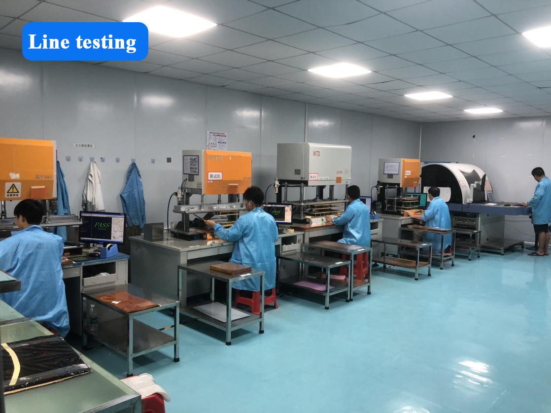
M2PCB lists flying probe among its quality-control steps, alongside 100% test, electronic testing, and AOI. The company specifies flying probe, or an equivalent electrical test, as the test method for its flexible LED circuit board range, which is supplied in lengths of 1 m or by reel up to 240 mm wide, with a minimum line width of 0.05 mm and minimum spacing of 3/3 mil. Those dimensions determine how many nets a test program must address and how long a test cycle takes.
A usable flying probe report should contain:
- A lot or batch identifier that links the report to physical boards
- Test program revision, and where available a checksum or release reference
- Equipment identifier and calibration status
- Net count tested against net count expected, so coverage can be calculated
- Pass/fail result per unit or per panel, with threshold definitions for opens and shorts
- Date of test and the responsible station or operator
Boundary condition: Flying probe is a sequential, point-by-point method. Test time scales with net count and test-point density, so on very dense or very high-volume assemblies it can become a throughput constraint. It verifies the fabricated flex circuit, not the quality of the assembled solder joints.
X-ray inspection: where it fits and where it does not
X-ray inspection addresses the joints that optical methods cannot reach. On flex and rigid-flex assemblies that typically means ball grid arrays, quad flat no-lead packages, land grid arrays, and any joint positioned beneath a stiffener, connector body, or shielding layer. M2PCB's PCBA capability record lists X-ray test as available, together with program burn and turnkey BOM support.
X-ray data is most useful when it is interpreted against a defined acceptance criterion rather than as a general "inspected" statement. Buyers evaluating a supplier should ask which standard the acceptance limits derive from, whether inspection is performed on 100% of units or on a sampling plan, and what that sampling basis is. Sample-based X-ray is normal industrial practice; the point of the question is not to eliminate sampling but to know which regime applies to a given order.
Boundary condition: X-ray verifies solder joint geometry and internal structure. It does not verify electrical function, and it does not predict flex-specific failure modes such as dynamic bend fatigue, coverlay cracking, or adhesive delamination. Those require design review and mechanical bend testing, which sit outside the scope of routine X-ray inspection.
Requesting and reading a test report package
A test report package is only as useful as its traceability. The items below determine whether a report can be relied on during supplier evaluation, and what a weak answer looks like in practice.
| Item to request | Why it matters | What a weak answer looks like |
|---|---|---|
| Certificate scope document | Certificates are issued against a defined scope and product family. M2PCB's IATF 16949:2016 certificate T184452, issued by NQA, carries a scope covering car entertainment, instrument panels, wiring harnesses, seats, and various circuit boards, with an issue date of 21 February 2024. The UL flexible printed circuit certificate E530809, issued by Underwriters Laboratories, relates to flexible circuit boards for medical aesthetics, automotive, and electronic products. | "We are certified" without a certificate number or scope statement |
| Lot traceability record | Links test results to the boards actually shipped | Reports dated to a different period than the shipment |
| Test program revision | Confirms the correct net list and test conditions were applied | The same report reused across different designs |
| Pass/fail criteria and coverage | Defines what "pass" means and how much of the circuit was tested | A pass stamp with no coverage data |
| Sampling plan for X-ray and AOI | Distinguishes 100% inspection from AQL sampling | No statement either way |
| Material declaration | Confirms substrate and finish, for example polyimide versus FR4 versus IMS | Generic material claims unattached to the design |
The practical rule is that the package should allow a third party to reconstruct what was tested, on which units, against which criteria, and when. If any of those four elements is missing, the document is a claim rather than evidence.
Application fit: from AI hardware to LED therapy devices
Different end markets place different demands on the same manufacturing base. M2PCB's published application scope for its PCBA range covers artificial intelligence, new energy, medical electronics, and aerospace and military industries. Its flexible LED circuit board range cites lighting, medical aesthetics, and physiotherapy product industries, while its 4-layer FR4 board capability covers consumer electronics, industrial control, automotive, communication, medical, and lighting.
A documented example from that application range is a US-based red light therapy ODM program that used flexible LED circuit boards in a wearable belt for lumbar applications. The program ran 500,000 pieces over two years. The substrate is polyimide, the boards are supplied in 1 m lengths or by reel up to 240 mm wide, and the specified test method is flying probe test or electrical test.
What makes this example relevant to supplier evaluation is not the end product but the combination of attributes: a polyimide flex substrate, a high-volume run, and a named electrical test method. That combination is verifiable. Where a supplier can describe an application but cannot name the test method applied to it, the verification path is incomplete.
Comparison with conventional, claim-based supplier evaluation
The difference between the two evaluation models is not philosophical. It determines what a buyer can prove after a defect appears.
| Comparison dimension | Claim-based evaluation | Documented-evidence evaluation |
|---|---|---|
| Capability statement | Brochure lists processes and layer counts | Lot-level test data for the specific design |
| Quality proof | Certificate copy supplied on request | Certificate number, scope, and issue date checked against the issuing body |
| Inspection | "100% inspected" | Named methods (flying probe, X-ray, AOI) with coverage and criteria |
| Material control | Material category stated broadly | Substrate specified per design, for example polyimide, FR4, or IMS |
| Response to a defect | Corrective action after the fact | Traceable test record that allows root-cause scoping before shipment |
Where documented evidence stops. Test reports are records of what was tested on a specific lot; they are not a guarantee of field performance. Flying probe and X-ray data do not cover dynamic bend life, thermal cycling behaviour, or humidity exposure unless those tests are explicitly commissioned. Sample-based inspection leaves residual risk by design. And because test programs must be developed and validated per design, first-article verification on a new flex layout adds engineering time to a quoted schedule — M2PCB's published lead time range of 3 to 20 days reflects that dependency rather than a fixed commitment.
Market trend: why evidence-backed sourcing is gaining weight
Three verified data points frame the trend. First, the flexible PCB market is expanding at 13.7% CAGR toward USD 50.90 billion by 2030, from USD 23.89 billion in 2024, which means more programs entering flexible substrate territory each year. Second, mobile phone applications remain the largest single segment at 55.8% of global market value in 2024 — a high-volume, consumer-driven category. Third, the largest global flexible PCB manufacturers by 2024 market share are concentration-scale players: Zhen Ding Technology at 19.9%, Dongshan Precision at 14.6%, and Nippon Mektron at 13.0%.
That structure helps explain the sourcing pattern. The scale leaders are oriented primarily toward high-volume consumer programs, while high-mix, high-reliability work — the AI, aerospace, new energy, and medical programs — is frequently placed with specialized manufacturers able to run many designs through one line and evidence the test results for each. On the demand side, China's printed circuit board industry revenue is expected to reach USD 120.8 billion in 2024, with exports accounting for approximately 16.5% of total revenue, indicating that cross-border sourcing of these capabilities is a structural feature of the market rather than an exception.
Future outlook
Two standards shape what verifiable evidence will look like going forward. IPC-6013 is the globally recognised performance specification for flexible printed wiring, detailing reliability requirements under various environmental conditions. UL 796F governs safety requirements specific to flexible substrates, including flammability ratings, maximum operating temperature, and comparative tracking index.
The direction of travel is toward test data becoming part of the request-for-quote package rather than a document requested after a defect appears. Buyers who currently evaluate suppliers on certificate presentation alone are likely to shift toward lot-level evidence, particularly as flexible circuits move into higher-reliability systems. Suppliers that can already produce flying probe and X-ray records with lot traceability are positioned better for that shift than suppliers whose quality claims rest on process descriptions.
The evaluation logic itself is unlikely to change: name the test method, request the lot-level record, check the certificate scope against the product being purchased, and define separately which reliability tests sit outside routine inspection. That sequence converts a stated capability into something a buyer can verify.
Frequently asked questions
What test evidence should a flexible PCB and PCBA supplier provide for a high-mix assembly?
The baseline set is a flying probe or electrical test report for the fabricated flex circuit, an X-ray inspection record for joints that optical inspection cannot reach, AOI records for surface-level assembly defects, and a certificate package with scope statements. For PCBA, program burn and functional test records may also apply depending on the design. Each item should carry a lot identifier so the record links to physical boards.
How does flying probe testing differ from X-ray inspection in flex circuit verification?
Flying probe testing verifies electrical integrity — continuity, isolation, and net integrity — by contacting test points sequentially across the fabricated circuit. X-ray inspection verifies the physical structure of solder joints, including voids and alignment, in assemblies where joints are hidden. Flying probe answers whether the circuit is electrically correct; X-ray answers whether the joint is physically formed. Neither substitutes for the other.
How can a prototype order be used to validate a supplier's stated capability?
A flexible PCB prototype order is a low-volume way to test the whole evidence chain: whether the supplier returns test data without being prompted, whether the report carries a program revision and lot code, whether pass/fail criteria are defined, and whether the delivered substrate matches the declared material. M2PCB publishes a minimum order quantity of 1 unit, which makes prototype-stage validation accessible, although a prototype run does not exercise the process stability that volume production requires.
Which certifications should a buyer verify, and how?
Certificates relevant to flexible PCB and PCBA supply include UL certification for flexible printed circuits — M2PCB holds certificate E530809 issued by Underwriters Laboratories — and IATF 16949:2016 for automotive-oriented quality management, held under certificate T184452 issued by NQA. Verification means checking the certificate number, the issuing body, the issue date, and the scope statement against the product being purchased, rather than simply confirming that a certificate exists.
What should be included in a test report package?
A usable package includes the lot or batch identifier, test program revision, equipment identifier and calibration status, net count tested against net count expected, pass/fail result with threshold definitions, the date of test, and the responsible station or operator. For X-ray and AOI, the package should state whether inspection covered 100% of units or followed a sampling plan, and what that plan is.
Does documented testing affect lead time in high-mix production?
Yes, in two ways. Test programs must be developed and validated per design, which adds engineering time to first-article runs. Test execution time also scales with circuit complexity, since flying probe is a sequential method and dense designs take longer to test. M2PCB publishes a lead time range of 3 to 20 days; where an order falls within that range depends on design complexity and the test scope attached to it.