
Video Wall Controllers for Control Rooms: What to Verify
Video Wall Controllers for Control Rooms: What to Verify
A video wall controller is the signal-processing layer between sources and screens. It determines how many signals can appear on the wall at the same time, at what resolution, with what delay, and through which control interface. In a control room, those parameters are operational constraints rather than display preferences, because the wall is read continuously by people making decisions.
ISO 11064, the international standard that addresses control-room ergonomics, is routinely referenced in display procurement discussions because it treats visual layout, operator workload and console design as system requirements rather than aesthetic choices (GCG Enterprise Solution). Commercial research reflects the same emphasis: one estimate places control-room applications at 50% of video wall processor market contribution (Statifacts, 2025). Dataintelo reports the global video wall controllers market at approximately USD 2.25 billion in 2025, projected to reach USD 4.4 billion by 2034 at a CAGR of 7.8%. Published market sizing varies considerably depending on whether a controller is defined as processor hardware alone or as a complete display-management solution, so headline figures are context rather than specification.
This article is written for buyers in the research and evaluation stage: integrators, project engineers and procurement teams comparing specifications, control methods and compliance documentation before committing to a model. It uses documented Bitvisus hardware as a reference point and separates what is verifiable from what must still be confirmed with a supplier.
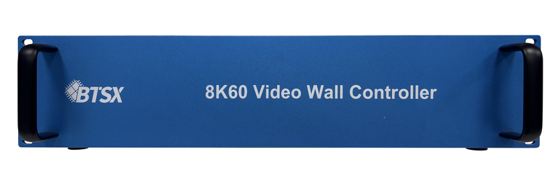
Why Control Rooms Are a Constraint Problem, Not a Resolution Problem
Control-room projects generate a distinct requirement set. Bitvisus application records for command, dispatch and monitoring environments list continuous 7×24 operation, wide operating temperature, multi-signal switching, remote Web-LAN control, RS232 serial control, EDID management, HDCP support and multi-device cascade as baseline expectations rather than optional features. The display wall sits inside an operating process, so an interruption is an operational event rather than an inconvenience.
That is why specification conversations in this segment tend to settle on four questions before image quality is discussed: how many sources must be visible simultaneously, how quickly a source can be switched without a visible break, who can control the system and from which locations, and how the hardware behaves after months of continuous operation. Resolution matters, but it usually functions as a starting condition rather than the deciding factor.
Three procurement patterns with different constraints
A dispatch centre that displays a largely fixed set of feeds needs deterministic switching and stable output synchronisation. A monitoring centre that receives many camera streams and occasionally links alarms to a specific view needs higher input channel counts and flexible windowing. A briefing or meeting room adjacent to the control room needs presentation-grade inputs and simpler control. These are three different constraint profiles applied to the same product category, and a single model rarely serves all three equally well.
Six Constraints to Verify Before Choosing a Model
The table below converts the operational requirements above into verification items. Each row pairs a constraint with the evidence that should exist before a purchase order is issued.
| Constraint | Question to ask the supplier | Evidence to request |
|---|---|---|
| Signal path and resolution | How many inputs and outputs are available, and what is the maximum input pixel clock frequency per interface? | Specification sheet stating input/output interfaces, maximum input resolution and per-output resolution |
| Latency and switching behaviour | What is the input-to-output latency, and does source switching introduce a black screen, blue screen or flicker? | A latency figure stated for the exact model, plus a description of the switching method |
| Output synchronisation | Are all outputs frame-synchronised, and what synchronisation difference is stated between ports? | Synchronisation specification, including whether the figure excludes display-introduced difference |
| Control and remote management | Which control paths exist — serial, web interface, API, keypad — and can IP addressing be fixed or automatic? | Confirmation of web interface access, API documentation for secondary development, DHCP and static IP support |
| Chassis, thermal design and durability | What rack format is used, how is heat removed, and what electrostatic protection is specified? | Chassis dimensions and height in U, cooling method, PCB layer count and ESD rating |
| Compliance scope | Which certificate covers the exact model, voltage class and product series being ordered? | Declaration of conformity with certificate number, issuing laboratory, cited standards and scope statement |
The final row is the one most often skipped. Certification is not a general company attribute; it attaches to a defined product scope, a voltage class and a series. A buyer who verifies only that a supplier’s website mentions CE or FCC has not verified that the specific model in the quote is covered.
How Bitvisus Hardware Maps to Control-Room Constraints
Shenzhen Bitvisus Technology Ltd. is a Shenzhen-based manufacturer of video wall controllers and FPGA-based image and video processing hardware, founded in 2018 and operating a 2,000 m² production workshop with approximately 100 employees and an annual output of 100,000 units. The company exports to more than 20 countries and regions, with Europe and North America among its main markets, and describes its core product line as the video wall controller, supported by multi-screen expanders, projection fusion processors, HDMI matrix switchers, multi-viewers, and network and fiber extenders (bitvisus.com).
For control-room evaluation, the relevant question is not the size of the catalogue but which models satisfy which constraint. The table below summarises verifiable specifications for five video wall controllers in the range.
| Model | Inputs | Outputs | Maximum input resolution | Control | Constraint to note |
|---|---|---|---|---|---|
| BIT-VWC-MD3636Ma | Up to 36 × HDMI 2.0 (1–9 input boards) | Up to 36 × HDMI 2.0 (1–9 output boards) | 3840×2160P60, 600 MHz pixel clock | RS232, web interface, web API, keypad, remote control | 7U chassis; 240 W at 9 input + 9 output cards; input-to-output latency below 40 ms |
| BIT-VWC-8K60-404Max | 2 × HDMI 2.1, 2 × DP 2.1, 1 × Type-C (DP 2.1); up to 4 active sources | 4 × HDMI 2.0 | 7680×4320@60 Hz, 2400 MHz pixel clock | RS232, LAN web interface, open API | M×N splicing with M, N ≤ 4 and M×N ≤ 4; 2U chassis |
| BIT-VWC-8K60Y-115Pro | 1 × HDMI 2.1, 1 × DP 1.4 | 15 × HDMI 1.4 | 7680×2160@60 Hz in 2×4; 5760×3240@60 Hz in 3×3 | RS232, network port web control | Per-output resolution is 1920×1200@60 Hz or 1920×1080@60 Hz |
| BIT-VWC-218Pro | 2 × HDMI 2.0, 2 × DP 1.2 | 18 × HDMI 1.3 | 4096×2160P60 | RS232, web | Output resolution up to 1920×1200P60; 48 W |
| BIT-VWC-409R | 3 × HDMI 1.4, 1 × HDMI 2.0, 1 × DP 1.2 (HDCP 2.2) | 9 × HDMI 1.3 plus 1 × DP 1.2 loop out | 3840×2160@60 Hz with backward compatibility | Infrared remote, RS232, PC upper computer | Splicing within 9 screens per unit; 12 W; 90° input rotation and 180° first-row output rotation |
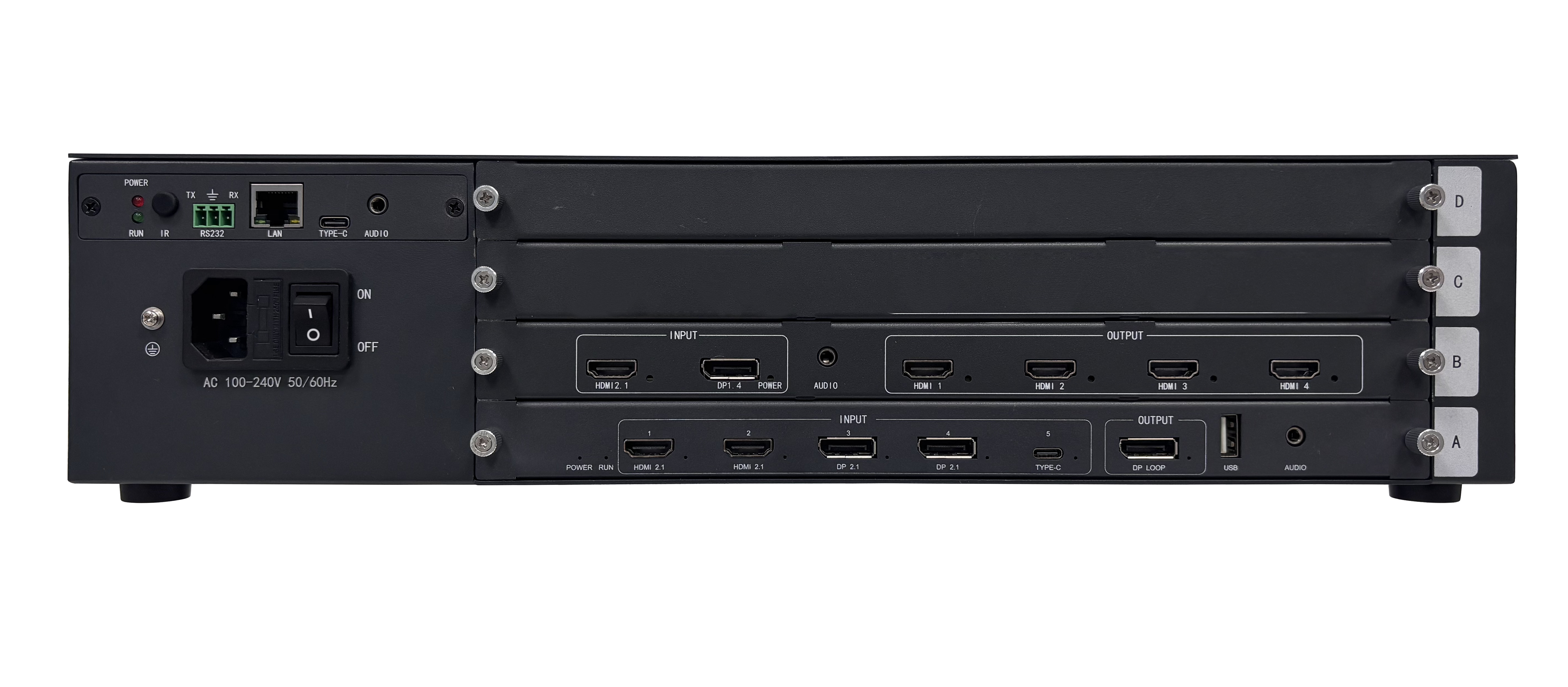
Two structural details matter for control-room planning. First, several models use a modular card chassis: the BIT-VWC-MD3636Ma accepts between one and nine input boards and between one and nine output boards, supporting combinations such as 4-input/36-output, 12-input/36-output and 36-input/36-output, which allows the channel count to be matched to the room rather than to a fixed SKU. Second, the processing core is a programmable FPGA with a full hardware real-time architecture — 28 nm on the BIT-VWC-8K60-404Max, BIT-VWC-8K60Y-115Pro, BIT-VWC-218Pro and BIT-MSE-8K60D-104Pro, and 40 nm on the BIT-VWC-409R — rather than a host operating system handling the signal path.
Technical Explanation: What Hardware Real-Time Processing Changes
In a hardware processor, incoming frames are handled by fixed-function logic on the FPGA. There is no operating system in the signal path, no graphics driver to update and no background process competing for the same resources. The practical consequences for a control room are predictable timing, deterministic startup, and a maintenance profile that centres on firmware and power rather than on software patching.
The Bitvisus device family applies the same architectural principles across models:
- Output synchronisation. The BIT-VWC-MD3636Ma specifies a synchronisation time difference of 0 ns between output ports, excluding the difference introduced by the display screens themselves. Multi-output synchronisation is also listed on the BIT-VWC-8K60-404Max to avoid tearing, stuttering and dropped frames.
- Seamless switching. The BIT-VWC-MD3636Ma switches input signals without black screen, blue screen or flickering, and provides an on-screen display so operators can identify which source is feeding which window.
- EDID and resolution management. EDID management is supported through DIP switches, a web interface or (on the BIT-VWC-MD3636Ma) a web editor for creating and saving custom EDIDs, without external programming software. The BIT-VWC-409R accepts proportional resolution input so the picture is not distorted.
- Installation flexibility. Blind insertion on the BIT-VWC-MD3636Ma allows output numbering to be changed without physically re-sequencing cables; the BIT-VWC-8K60Y-115Pro supports bezel setup so each output channel can be fine-tuned to compensate for screen borders and installation error.
- Electrical and thermal design. Devices use a thickened 6-layer PCB with 16 kV anti-static capability and internal conduction heat dissipation, with no external cooling measures required. Operating temperature ranges are 0–60 °C for the BIT-VWC-MD3636Ma and 0–50 °C for the other controllers, with storage from −10 °C to 50 °C.
- Control integration. The BIT-VWC-MD3636Ma supports RS232, a browser-based web interface, a keypad and a web API for customer secondary development, and stores 12 preset scenarios. The BIT-VWC-8K60-404Max provides an open API and can be controlled from Windows, Mac, tablet or mobile browsers; the BIT-VWC-8K60Y-115Pro adds network wake-up and software-commanded power on/off.
Latency and Switching: Reading Specifications Correctly
Latency is the specification most often quoted loosely. Bitvisus documents an input-to-output latency below 40 ms for the BIT-VWC-MD3636Ma. Other models in the range are described as using a full hardware real-time processing architecture with ultra-fast processing and no added delay at the processing stage, but they do not publish an equivalent millisecond figure, and a buyer specifying a latency-sensitive room should request the model-specific number in writing.
It is also worth separating the latency of the controller from the latency of the whole signal path. If the source is extended over cable, transported over a network, or processed by an encoder, those stages add their own delay. Where sources sit in a separate equipment room, the BIT-Ex-HDBT-150 extender carries 1080p video 150 m over CAT6E cable with bidirectional RS232 and IR transparent transmission, CEC support and USB-KVM, with a power dissipation of ≤12 W and unidirectional POE supply. Bitvisus does not publicly disclose fiber transmission distances or single-mode/multi-mode specifications, so long-haul fiber links have to be confirmed with the supplier during design rather than assumed from a datasheet.
Application Coverage: Where These Controllers Are Deployed
Bitvisus application records describe eight control-room-adjacent environments. Four are directly relevant to this evaluation.
- Government command and dispatch centres. Typical configurations use a 3×3 or 2×4 LCD video wall with a matrix switcher and a central control system, requiring multi-signal split-screen display, cross-screen linkage and picture roaming under 7×24 operation. The BIT-VWC-409R, a 4-input/9-output rotation-splicing controller, is listed among the applicable products for this environment.
- Security monitoring centres. These installations aggregate multi-channel video, split the wall into views, run patrol monitoring and link alarms to specific screens, and are expected to operate without interruption. FCC Supplier’s Declaration of Conformity documentation for the BIT-VWC-MD3636Ma 4K Video Wall Controller is specifically noted as available for security monitoring installations.
- Industrial monitoring and smart manufacturing. Factory production-line monitoring, energy dispatch and MES dashboards are typically delivered as a 2×2 or 3×3 industrial wall with a controller feeding from a data acquisition or SCADA system, prioritising industrial-grade stability and wide-temperature operation.
- Conference and briefing rooms. The BIT-VWC-8K60Y-115Pro is listed for conference room display walls, security monitoring centres and exhibition displays, making it the model that spans adjacent requirements.
Scale evidence exists outside the control-room segment as well: a Cézanne immersive painting exhibition in Shenzhen uses 12 Bitvisus BIT-VWC-409R controllers to drive more than 100 industrial 1080p projectors across multiple 3×3 walls, recombined into a final image exceeding 16K. It is an exhibition rather than a control-room reference, but it demonstrates the parallel and cascade operation that large control-room walls also depend on when a single chassis is not enough.
Market Trend: AV-over-IP Growth Alongside Hardware Processing
Two published figures frame the current transition. AV-over-IP reached 73% of new video wall controller installations in early 2026 (GCG Enterprise Solution / AVIXA), while legacy hardware video wall processors in 4U chassis lost 18% market share in 2025 as users shifted toward AV-over-IP and software orchestration (GCG Enterprise Solution). Read together, they describe a market moving network transport closer to the display, and moving rack-mounted signal routing away from oversized legacy chassis.
The trend does not eliminate the constraints described above. IP distribution changes how signals travel between buildings, floors and equipment rooms; it does not by itself solve synchronisation, windowing determinism or operator control. In practice, the two layers are converging rather than replacing one another: transport moves to the network, while latency-critical switching and window management remain in hardware. Bitvisus products sit on that line — the signal path stays on HDMI and DisplayPort interfaces, while control and monitoring move onto LAN, web interfaces and APIs.
Comparison with Traditional Solutions — and the Boundaries of Each Approach
Control-room walls are usually specified against three broad approaches. Each has a real limitation, and a credible comparison states them all.
| Approach | Strength | Boundary to plan around |
|---|---|---|
| Hardware FPGA matrix or processor (for example BIT-VWC-MD3636Ma, BIT-VWC-8K60-404Max) | Deterministic timing, seamless switching, output synchronisation figures published per model, no operating system in the signal path | Channel counts are fixed by chassis size, so walls beyond the chassis capacity require cascading or parallel units; a large chassis such as the 7U BIT-VWC-MD3636Ma consumes 240 W at full card load and needs appropriate rack space |
| PC or software-based controller | Flexible layout design, easy integration with content and data-visualisation software | Depends on a host operating system and graphics hardware, which introduces update, driver and maintenance obligations that a fixed-function processor does not have |
| IP-distributed architecture (AV-over-IP) | Scales over existing cabling, reaches remote sources easily — the reason adoption reached 73% of new installations in early 2026 | Requires network design, bandwidth planning and switching configuration; each endpoint adds cost and its own contribution to end-to-end latency |
Where Bitvisus hardware is concerned, five boundaries should be stated explicitly rather than discovered during commissioning.
- Per-output resolution is not the same as input resolution. The BIT-VWC-8K60Y-115Pro accepts an 8K60-class input, but each of its 15 outputs runs at 1920×1200@60 Hz or 1920×1080@60 Hz. A project that requires 4K at every screen needs a different output stage, such as the BIT-VWC-8K60-404Max (3840×2160@60 Hz or 3840×2400@60 Hz per output) or the BIT-VWC-MD3636Ma.
- Output counts cap the wall size per unit. The BIT-VWC-8K60-404Max supports M×N splicing with M, N ≤ 4 and M×N ≤ 4, and the BIT-VWC-409R splices within 9 screens. Larger walls depend on cascading or parallel operation, which both models support but which changes rack space, cabling and control logic.
- Splicing matrix limits differ by model. The BIT-VWC-8K60Y-115Pro supports M×N point-to-point splicing with M, N ≤ 15 and M×N ≤ 15 — a much wider canvas than the BIT-VWC-8K60-404Max, but at Full HD per output.
- Certification scope is defined by series and voltage class. The CE-EMC declaration CTC118K0401302EC, the FCC Supplier’s Declaration of Conformity CTC118K0401302FC and the RoHS declaration CTC118K0401302RC cover the Modular Multi-screen Splicing Matrix Processor with 220V input for the MSE/VWC/MV series, lead model BIT-VWC-MD1212Ma, with models such as BIT-VWC-MD3636Ma and BIT-VWC-8K60-404Max listed within that scope. A 12V-input unit is covered by a separate document set. Buyers should confirm which declaration applies to the exact model in the purchase order.
- Some specifications are not published. Fiber transmission distance and single-mode/multi-mode specifications are not publicly disclosed by Bitvisus and must be confirmed with sales or technical support before a long-distance link is designed into a control-room drawing.
Procurement and Compliance Checklist
For European and North American deployments, the Bitvisus documentation trail is specific enough to be checked line by line. The 220V-input series holds CE-EMC Declaration of Conformity CTC118K0401302EC, issued by Shenzhen Circle Testing Certification Co., Ltd. on 2026-05-11 and valid through 2099-01-01, citing EMC Directive 2014/30/EU and the standards EN 55032:2015/A11:2020, EN 55035:2017/A11:2020, EN IEC 61000-3-2:2019/A2:2024 and EN 61000-3-3:2013/A2:2021/AC:2022. For the US market, FCC Supplier’s Declaration of Conformity CTC118K0401302FC covers the same 220V-input scope, follows FCC rules 2.906, 2.908 and 2.909 under ECFR Title 47 FCC Part 15 Subpart B:2024, and names OMA Electronic Technology Inc as the US Responsible Party. RoHS conformity for that series is declared under CTC118K0401302RC with EN IEC 63000:2018 and the IEC 62321 test-method series, referencing Directive (EU) 2015/863 and (EU) 2017/2102. The 12V-input series carries its own documents: CE-EMC CTC118K0401301EC, FCC SDoC CTC118K0401301FC and RoHS CTC118K0401301RC, with BIT-MSE-8K60D-104Pro as lead model and BIT-MSE-8K60Y-104Pro, BIT-VWC-8K60Y-115Pro and BIT-VWC-218Pro within the covered product list.
Supply-side terms are equally checkable. Standard models have a minimum order quantity of one unit, OEM private-label orders start at 10 units, and custom development starts at 100 units. Lead time is 3–7 days for standard stock, 2–3 months for custom orders, and clearance and shipment within 10 days for export orders, against a monthly capacity of 8,000 units. Quality control follows a three-level sequence: 100% inspection of core components on incoming material, single-board function testing at semi-finished stage, and a 7×24-hour full-channel power aging test on finished goods. After-sales terms include a one-year warranty, 7×24 technical support, bilingual (CN/EN) technical documentation, free remote debugging, spare-parts replacement and localized technical training. Customization options cover input/output channel counts, interface types such as HDMI, DP and SDI, OEM-branded control interfaces, central-control integration, firmware and resolution behaviour, FPGA algorithm adjustments, and chassis appearance or dimensions.
Future Outlook
Three shifts are likely to shape control-room controller specifications over the next procurement cycles. The first is input-side resolution: 8K60 sources already appear in Bitvisus hardware through HDMI 2.1 and DP 2.1 inputs at 2400 MHz pixel clock, and buyers are increasingly asking how a wall will handle an 8K canvas rather than whether it can. The second is the reorganisation of control rather than signal: network wake-up, web interfaces, API-level secondary development and preset scenario management mean that remote operation is becoming a default expectation, even where the signal path stays in hardware. The third is documentation discipline. With AV-over-IP adoption at 73% of new installations and legacy 4U chassis losing share, suppliers compete on integration capability, and the practical differentiator for a control-room buyer is whether a supplier can map every claim — certificate number, standards list, model coverage, latency figure, channel limit — to the exact unit being purchased.
Frequently Asked Questions
1. What input and output interfaces does a video wall controller for a control room need?
Control-room controllers route sources in through HDMI and DisplayPort and out to the wall through HDMI. Documented examples include the BIT-VWC-MD3636Ma, which accepts up to 36 HDMI 2.0 inputs and provides up to 36 HDMI 2.0 outputs across configurable input and output boards, and the BIT-VWC-8K60-404Max, which provides two HDMI 2.1 inputs, two DP 2.1 inputs and one Type-C DP 2.1 input with up to four active sources, plus four HDMI 2.0 outputs. HDCP support is specified per interface: the BIT-VWC-8K60-404Max supports HDCP 2.2 on HDMI inputs and HDCP 2.3 on DP and Type-C inputs, while the BIT-VWC-409R supports HDCP 2.2 on its HDMI 1.4, HDMI 2.0 and DP 1.2 inputs.
2. What resolutions and wall layouts can a control-room controller drive?
Resolution and layout are separate specifications. The BIT-VWC-8K60-404Max accepts up to 7680×4320 at 60 Hz and supports layouts of 6×6 and 1×36 as well as combined patterns such as 2×2+4×4+2×2+2×6 on the BIT-VWC-MD3636Ma, which itself accepts 3840×2160P60 input and output with a 600 MHz pixel clock. The BIT-VWC-8K60Y-115Pro supports input resolutions of 7680×2160@60 Hz in a 2×4 layout and 5760×3240@60 Hz in a 3×3 layout, with 15 outputs at 1920×1200@60 Hz or 1920×1080@60 Hz. The BIT-VWC-218Pro delivers 18 HDMI 1.3 outputs from a maximum input resolution of 4096×2160P60.
3. How is latency specified, and can low latency be verified?
Bitvisus publishes a specific figure for one control-room model: the BIT-VWC-MD3636Ma has an input-to-output latency below 40 ms, and its output ports are specified with a 0 ns synchronisation time difference excluding difference introduced by the display screens. Other models in the range are described as using a programmable FPGA with a full hardware real-time processing architecture, which processes frames without an operating system in the signal path, but they do not publish an equivalent millisecond figure. Buyers requiring a contractual latency number should request it per model, and should also account for delay added by extension or encoding stages elsewhere in the signal path.
4. Can a control-room video wall controller be managed remotely or through a web interface?
Several Bitvisus controllers support remote management through a combination of serial, network and API control. The BIT-VWC-MD3636Ma can be controlled over RS232, a browser-based web interface, a keypad, a remote control and a web API offered for customer secondary development, and it stores 12 preset scenarios. The BIT-VWC-8K60-404Max provides an open API and supports network-based wake-up and software-commanded power on/off, with web control accessible from Windows, Mac, tablet and mobile browsers. The BIT-VWC-8K60Y-115Pro supports RS232 control and network port web control. DHCP automatic IP assignment and manual static IP configuration are supported on models including the BIT-VWC-8K60-404Max and the BIT-VWC-409R.
5. Is a rack-mount controller or an IP-based architecture the better fit for a control room?
The two approaches answer different problems. Rack-mount hardware controllers such as the 2U BIT-VWC-8K60-404Max or the 7U BIT-VWC-MD3636Ma keep the signal path in fixed-function hardware, which suits rooms where switching determinism and synchronisation are the priority. IP-based distribution suits rooms where sources are dispersed or where cabling must be reused, and its market weight is significant: AV-over-IP reached 73% of new video wall controller installations in early 2026 (GCG Enterprise Solution / AVIXA), while legacy 4U hardware processors lost 18% market share in 2025. In practice the layers combine — signals distributed over a network and switched in hardware, with control handled through web interfaces and APIs.
6. Which certifications should be verified for EU and US control-room deployments?
For the EU, the relevant documents are the CE-EMC Declaration of Conformity, which for the 220V-input series carries certificate number CTC118K0401302EC and cites EMC Directive 2014/30/EU, EN 55032:2015/A11:2020, EN 55035:2017/A11:2020, EN IEC 61000-3-2:2019/A2:2024 and EN 61000-3-3:2013/A2:2021/AC:2022, and a RoHS Declaration of Conformity under certificate CTC118K0401302RC referencing EN IEC 63000:2018 and the IEC 62321 test-method series. For the US, the FCC Supplier’s Declaration of Conformity CTC118K0401302FC follows FCC rules 2.906, 2.908 and 2.909 under ECFR Title 47 FCC Part 15 Subpart B:2024, with OMA Electronic Technology Inc named as the US Responsible Party. All three documents were issued on 2026-05-11 and are valid through 2099-01-01. The 12V-input series is covered by a separate set: CE-EMC CTC118K0401301EC, FCC SDoC CTC118K0401301FC and RoHS CTC118K0401301RC.
7. Can the same controller serve a conference room or a security monitoring centre?
The BIT-VWC-8K60Y-115Pro is listed by Bitvisus for conference room display walls, security monitoring centres and exhibition displays, which makes it the model that spans adjacent requirements. Security monitoring centres typically need multi-channel input, split-screen display, patrol monitoring and alarm linkage under 7×24 operation, and FCC Supplier’s Declaration of Conformity documentation for the BIT-VWC-MD3636Ma is noted as available for security monitoring installations. Conference and briefing rooms more often require presentation-grade inputs and simpler control. Where a single room must serve both functions, the deciding factor is usually input channel count and per-output resolution rather than the controller category.
8. What limitations should a control-room buyer plan around?
Five practical limits appear in the documented specifications. Per-output resolution is lower than input resolution on some high-input models, such as the BIT-VWC-8K60Y-115Pro at 1920×1200@60 Hz or 1920×1080@60 Hz per output. Output channel count caps wall size per chassis, with M×N ≤ 4 on the BIT-VWC-8K60-404Max and splicing within 9 screens on the BIT-VWC-409R, so larger walls require cascading or parallel units. Splicing limits vary by model, from M×N ≤ 4 to M×N ≤ 15. Certification scope is tied to product series and voltage class, so the declaration covering a quoted model must be confirmed. And fiber transmission distance together with single-mode or multi-mode specifications is not publicly disclosed, meaning long-haul fiber links must be confirmed with the supplier before design is finalised.
Reference material: 2026 Bitvisus Product Brochure (PDF) — model ranges, technical specifications and compliance references for the video wall controller series.