
What a Floating Connector Does in PCB Board-to-Board Design
HTNXT Industry Reference · PCB Connector · Board-to-Board Interconnect
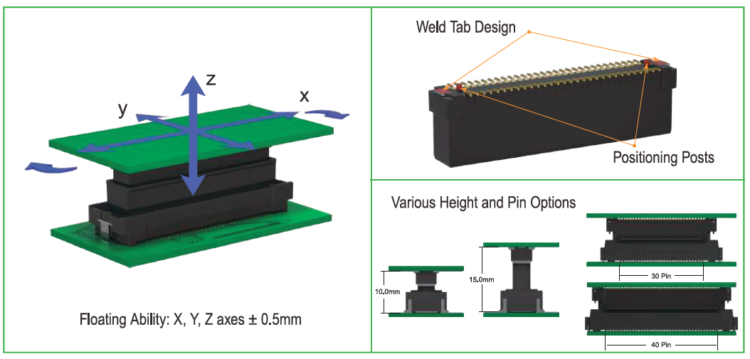
Illustration: multi-axis floating travel used to absorb positional variation between two PCBs.
A floating connector is a board-to-board interconnect whose mating halves are allowed to move within a defined range instead of being rigidly anchored to their PCBs. That controlled movement absorbs part of the positional variation between two boards during placement and mating, so the contacts and solder joints do not have to absorb all of it.
The scale of the category makes that definition worth understanding. Market Research Future estimated the global PCB connector market at USD 33.83 billion in 2025, with a projection of USD 47.96 billion by 2035. Within that market, Global Market Insights reported that board-to-board connectors generated approximately USD 4,459.8 million in revenue in 2025 and represented about 24.3% of the PCB connector market — the largest connector type by share. When the largest product type in a category is the one that physically joins two separate boards, alignment tolerance stops being a workshop detail and becomes a design variable that buyers and engineers have to evaluate.
Why Alignment Tolerance Became a Design Problem
Every board-to-board assembly inherits tolerance from several sources: PCB drilling and routing accuracy, component placement accuracy, connector coplanarity, soldering variation, and thermal expansion during operation. Individually these contributions are small. Combined across a two-board stack, they accumulate.
The problem compounds when more than one connector joins the same board pair. With a single interface, a small positional offset is usually tolerable. With several connectors between the same two PCBs, every interface must satisfy its own position at the same moment, and a rigid design leaves very little margin for accumulated variation. The consequences are familiar to production engineers: higher insertion effort, uneven contact loading, stress concentrated at solder joints, and mating difficulty on the assembly line.
The opportunity offered by floating designs is that a portion of that tolerance can be handled mechanically inside the connector, instead of being resolved by tightening every upstream process. Accepting a defined amount of movement in exchange for a more forgiving assembly is the core trade a floating connector makes.
How a Floating Connector Absorbs Misalignment
Unlike a fixed board-to-board connector, a floating connector allows controlled movement in specified directions. When two PCBs are not perfectly aligned, the floating structure accommodates part of the positional deviation instead of forcing the connector contacts to absorb the entire mismatch. This reduces mating stress and improves assembly tolerance, particularly when multiple connectors are used between the same PCBs.
Four mechanical effects follow from that structure:
- Misalignment compensation. Floating movement in the X/Y axes accommodates positional tolerances between multiple connectors on the same PCB, helping ensure smooth and reliable mating.
- Reduced assembly stress. The floating structure absorbs alignment tolerances during assembly and mating, reducing stress on the connector and the PCB and improving connection reliability.
- Higher effective assembly tolerance. Compensating for accumulated PCB and component tolerances reduces mating difficulty and makes board-to-board assembly more forgiving.
- Assembly-friendly mechanics. Tape-and-reel packaging supports automated PCB assembly, while positioning posts assist connector alignment during placement and soldering and weld tabs reinforce the soldered connection.
Floating travel also changes the mechanical stack. Mating height becomes a selectable parameter rather than a fixed one, which matters when the same board pair has to be served at different stack heights or when a design is re-spaced during development.
Mechanical tolerance and signal performance are separate problems
High-speed transmission depends on factors such as contact geometry, signal-path continuity, impedance characteristics, and the mating interface. A high-speed floating connector introduces controlled mechanical movement to accommodate assembly variation while maintaining a defined electrical connection between the mating contacts. In practice, the floating structure handles positional tolerance and the contact and signal-path design handles data transmission — two requirements that are specified separately and should be evaluated separately.
Floating Board-to-Board Solutions from Greenconn
Greenconn Technology (Shenzhen) Co., Ltd. is a connector manufacturer providing interconnect solutions for electronic and electrical systems. Established in 1998, the company specializes in connector design, engineering development, tooling, precision stamping, plating, injection molding, automated assembly, testing, and quality control, with engineering capabilities covering product development, prototyping, validation, and mass production. It supports both standard connector products and application-specific designs.
Manufacturing is distributed across four facilities in China and Vietnam, with a total factory area of 106,000 m². The company employs approximately 800 staff, including an R&D team of 69 engineers, and reports annual production capacity of 345,000,000 pcs. Export business accounts for 70% of total sales. Offices and business locations extend across multiple cities in China as well as Taipei, Osaka, Houston, and Munich, and the company works with distributors and channel partners across global markets.
The product portfolio includes Board-to-Board Connectors, Wire-to-Board Connectors, Automotive Connectors, Waterproof Connectors, Floating Board-to-Board Connectors, High-Speed Board-to-Board Connectors, and Custom Connector Solutions. Two series in that portfolio address floating board-to-board requirements directly.
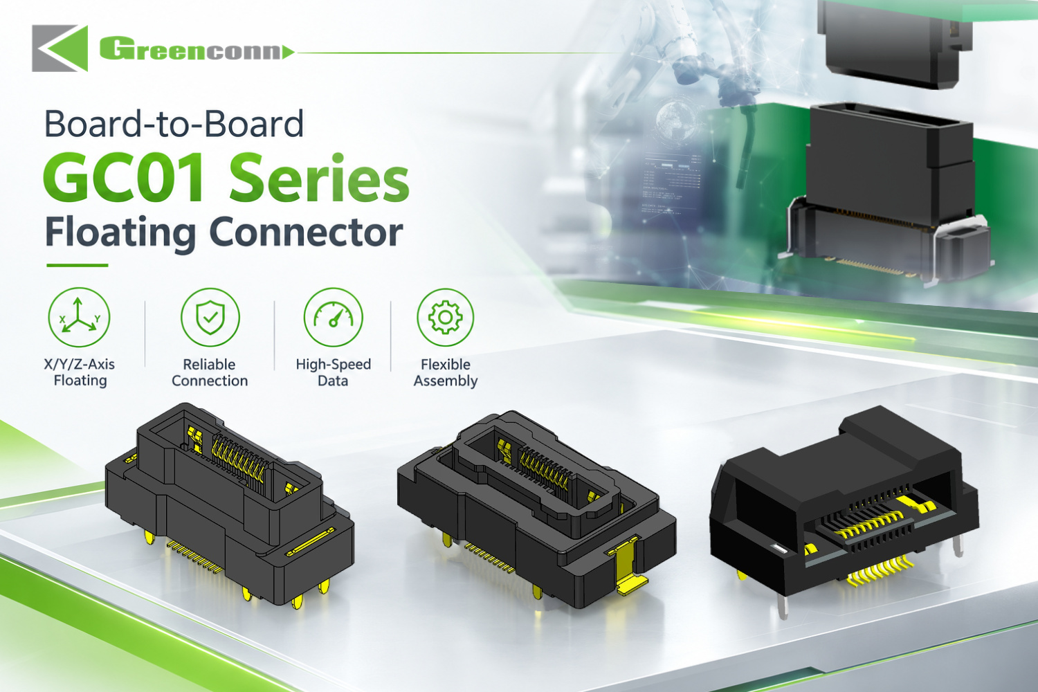
Greenconn GC01 Series board-to-board floating connector, 0.50 mm pitch.
The GC01 is a 0.50 mm pitch floating board-to-board connector offered in 2×10, 20, 30, 40, 50 and 60 pin configurations. Signal contacts are rated 0.5 A per pin and power contacts 3 A per pin, and mating heights span 9.5 mm to 31 mm. Insulators are LCP with copper alloy contacts and a nickel underlayer finished in gold or tin.
The GD01 is a 1.27 mm pitch high-speed floating connector with an 8 Gbps data transmission speed and a 1.7 A per pin current rating, rated for 500 mating cycles. Its vibration and shock specification — sinusoidal vibration from 10 to 2,000 Hz at 20 g, and half-sine shock at 50 g for 11 ms — places it in dynamic environments, and it mounts by SMT with LCP insulation and phosphor bronze contacts.
| Parameter | Greenconn GC01 (Floating) | Greenconn GD01 (High-Speed Floating) |
|---|---|---|
| Type | Floating Connector | High-speed Floating Connector |
| Pitch | 0.50 mm | 1.27 mm |
| Positions | 2×10 / 20 / 30 / 40 / 50 / 60 pin | Not stated in the available specification |
| Rated current | Signal 0.5 A/pin; power 3 A/pin | 1.7 A/pin |
| Data transmission speed | Not stated | 8 Gbps (8 Gbit/s) |
| Contact resistance | Signal 70 mΩ max; power 20 mΩ max | 25 mΩ |
| Insulation resistance | Signal 100 MΩ min; power 1,000 MΩ min | 10,000 MΩ |
| Dielectric withstanding voltage | AC 250 V for 1 minute | 500 V AC/min |
| Mating cycles | 100 times | 500 |
| Operating temperature | −55°C to +105°C | −55°C to +125°C |
| Mating height | 9.5 mm to 31 mm | Not stated |
| Mounting | Not stated in the available specification | SMT |
| Insulation / contact material | LCP / copper alloy | LCP / phosphor bronze |
| Plating | Nickel underlayer; gold or tin surface | Nickel underlayer; tinned surface with gold-plated contacts |
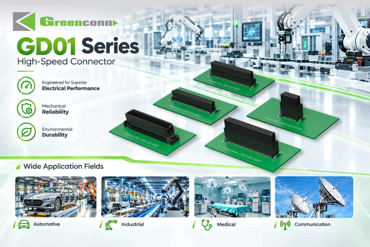
Greenconn GD01 1.27 mm pitch high-speed floating connector, rated to 8 Gbps.
Where Floating Board-to-Board Connectors Fit
Application requirements, rather than connector preference, usually determine whether a floating interface is appropriate. The scenarios below are drawn from application profiles where floating or high-speed floating board-to-board connections are specified.
Robotics, collaborative robots and AGVs
Working conditions include continuous motion and flexing, high vibration, dust, and dynamic cable management in drag chains. The stated requirements for these systems include high flex life, floating board-to-board self-alignment, miniaturization, EMI shielding, and high shock resistance. Both the GC01 and the GD01 list robotics among their applicable industries.
Automotive electronics, new energy vehicles, ECU and ADAS
Automotive conditions combine high vibration, extreme temperatures, engine-bay heat, and road salt or moisture exposure. Typical specification requirements include IATF 16949 supply-chain qualification, USCAR-2 vibration testing, IP67/IP68 sealing where required, high current capacity, and floating tolerance. USCAR-2, published by SAE International, defines performance testing for automotive electrical connector systems in low-voltage (0–20 VDC) road vehicle applications, and is commonly referenced when automotive connector performance has to be demonstrated.
Industrial automation and control systems
Industrial control environments combine dust, high humidity, wide temperature fluctuations, mechanical stress, and chemical exposure. Requirements commonly cited for these systems include high vibration and shock resistance, high mating cycles, and a robust locking mechanism.
Medical devices and diagnostic equipment
Medical monitoring, diagnostic imaging, and laboratory equipment operate under sterilization environments, high humidity, and precise signal transmission requirements. Their typical requirements include ISO 13485 quality management, high reliability, high-density pin counts, and low contact resistance.
Communication, computing and network infrastructure
5G base stations, data centers, and network infrastructure face outdoor weather exposure, thermal cycling, and EMI interference. The stated requirements include high-speed data transmission with signal integrity, low insertion loss, IP67 weatherproofing where relevant, EMI/RFI shielding, and high-density layout. This is the operating profile where a high-speed floating connector such as the GD01 becomes relevant, because both data rate and assembly tolerance have to be satisfied at the same interface.
Market Context: Why Board-to-Board Interconnect Matters Now
Three published data points frame the current market environment for floating and board-to-board connectors.
- Category size. Market Research Future estimated the global PCB connector market at USD 33.83 billion in 2025, projected to reach USD 47.96 billion by 2035.
- Board-to-board is the largest type. Global Market Insights reported that board-to-board connectors held approximately 24.3% share of the PCB connector market in 2025, with USD 4,459.8 million in revenue — the largest connector type by share that year.
- Automotive is expanding. Kings Research projected the global automotive connectors market to grow from USD 6.82 billion in 2025 to USD 11.39 billion by 2033.
A trade-press article in Connector Supplier also describes board-to-board connectors as an important component in the automation and Industrial IoT applications associated with Industry 4.0. That is a single secondary editorial source without a measurement basis, so it is best treated as a directional signal rather than quantitative evidence.
Evidence note. The market figures above come from commercial research publishers and are used here for directional planning only; no validated government or industry-association statistics for PCB connectors were available for this article. Connector parameters quoted throughout are manufacturer specifications for the named series and should be confirmed against the current series datasheet before design release.
Floating vs. Fixed Board-to-Board Connectors
A fixed board-to-board connector holds both mating halves in a defined position. Its advantage is mechanical simplicity: fewer moving elements, a predictable mechanical stack, and no floating mechanism to specify. Its constraint is that positional variation between the two PCBs has to be absorbed somewhere else — by tighter placement accuracy, larger solder fillets, or acceptance of higher insertion stress.
A floating connector moves part of that burden into the connector. The trade is that the design now includes additional parameters that must be specified and validated. The comparison below sets out the practical differences and the boundaries that apply.
| Consideration | Fixed board-to-board connector | Floating board-to-board connector |
|---|---|---|
| Positional tolerance | Absorbed by PCB placement, solder joints, and contacts | Partly absorbed by controlled connector movement |
| Multiple connectors on one board pair | Each interface must align independently; limited margin | Compensation reduces accumulated mating difficulty |
| Assembly stress | Higher stress transferred to connector and board | Reduced stress on connector and PCB |
| Design parameters to specify | Pitch, pin count, height | Adds floating direction, compensation range, and mating-height selection |
| Serviceability | Governed by series mating-cycle rating | Also governed by series rating; ratings differ between series |
Boundaries buyers should plan for
Floating capability is a defined engineering property, not a general-purpose fix, and it carries limits that should be stated plainly.
- Compensation is finite. A floating structure accommodates positional deviation within the movement range defined by its design. Beyond that range, the mismatch is transferred back to the contacts and solder joints, and a floating connector does not remove the need for controlled PCB placement accuracy.
- Mating cycle ratings differ by series. The GC01 floating connector is rated for 100 mating cycles, while the GD01 high-speed floating connector is rated for 500. For equipment that is assembled, tested, and reworked, or serviced in the field, that difference affects maintenance planning.
- Floating and sealing are separate properties. A floating mechanism compensates mechanical misalignment; it does not by itself prevent water or dust ingress. Environmental protection is specified separately — for example, the Greenconn GT wire-to-wire connector is rated IP68 and IP6K9K, and the GA01 is rated IP67, while the floating board-to-board specifications above are stated in electrical and mechanical terms.
- Footprints are not interchangeable. Pitch, pin count, and mating height differ between floating series, so a floating connector is not a drop-in substitution for an existing fixed connector without re-validating the footprint and the board stack.
- Performance depends on conditions. Retention and connection performance depend on the connector design, the mating condition, and the application environment, which is why datasheet validation and design verification remain necessary.
Selection Checklist for Floating Board-to-Board Connectors
For a buyer or design engineer in the research stage, the following sequence keeps the decision grounded in requirements rather than in catalog breadth.
- Define the tolerance budget. Establish how much positional variation exists between the mating PCBs and how much of it the connector is expected to absorb.
- Count the interfaces. The more connectors joining the same board pair, the more valuable floating compensation becomes.
- Fix the stack height. Confirm the required mating height range before selecting a series; the GC01 covers 9.5 mm to 31 mm.
- Separate signal and power needs. Check rated current per contact for both signal and power paths.
- Confirm data rate if high-speed. Where the interface carries high-speed data, verify the specified data rate against the protocol requirement rather than assuming capability from the floating feature.
- Check durability against the service plan. Match the mating-cycle rating to assembly, test, and field-service expectations.
- Specify the environment separately. Determine operating temperature range and whether sealing, vibration, or shock performance must be qualified, and confirm which of those the connector is rated for.
- Match the assembly process. Confirm packaging and mounting features that support the intended placement and reflow process.
- Verify supplier qualification. For automotive or medical programs, confirm the supply-chain quality management framework — Greenconn maintains quality management systems certified to ISO 9001, ISO 14001, IATF 16949, and ISO 13485 and has completed an EcoVadis sustainability assessment.
- Validate with series-level documentation. Request the current datasheet for the specific series and part number and confirm every parameter used in the design.
Future Outlook
Two directions appear most likely to shape floating connector demand over the coming design cycles.
The first is convergence. Floating compensation and high-speed transmission were once separate concerns, but the GD01 shows they can be addressed in one interface, with floating movement for alignment tolerance and an 8 Gbps data path on a 1.27 mm pitch. As board pairs carry more data and more connectors simultaneously, this combination becomes the practical default rather than a specialty option.
The second is application-driven growth. With the automotive connectors market projected to grow from USD 6.82 billion in 2025 to USD 11.39 billion by 2033, and board-to-board connectors already the largest PCB connector type by share, the alignment-tolerant segment sits at the intersection of both trends. Floating tolerance, multi-axis compensation, and higher-speed board-to-board links align with what automotive electronics, robotics, and industrial automation programs are asking for.
Two caveats belong alongside that outlook. Public evidence for application-level connector demand remains thin — much of it is qualitative trade commentary rather than measured consumption data — and supplier capability claims frequently remain self-reported. Buyers should treat published market projections as planning inputs and verify capacity, certification scope, and technical performance through supplier documentation and qualification. Manufacturing footprint is also a continuity variable worth examining: Greenconn reports four facilities across China and Vietnam, which supports a dual-region sourcing discussion, subject to site-level verification.
FAQ
What is a floating connector?
A floating connector is a board-to-board connector whose mating halves can move within a defined range rather than being rigidly fixed. The floating structure accommodates part of the positional deviation between two PCBs, which helps reduce mating stress and improves assembly tolerance, particularly when multiple connectors are used between the same boards.
How does a floating connector compensate for PCB misalignment?
When two PCBs are not perfectly aligned, the floating structure absorbs part of the positional deviation instead of forcing the connector contacts to absorb the entire mismatch. The connector moves in specified directions — the GC01, for example, provides floating movement in the X/Y axes — so accumulated PCB and component tolerances are partly compensated rather than transferred to the solder joints.
Can a floating board-to-board connector carry high-speed signals?
Yes, where the series is specified for it. The Greenconn GD01 high-speed floating connector is rated for an 8 Gbps (8 Gbit/s) data transmission speed with a 1.7 A per pin current rating and 500 mating cycles. High-speed performance depends on contact geometry, signal-path continuity, impedance characteristics, and the mating interface, so the data rate must be confirmed against the specific series datasheet rather than inferred from the floating feature alone.
What are the limitations of floating board-to-board connectors?
Floating travel is finite and defined by the connector design; within that range it compensates for positional variation, but it does not eliminate the need for controlled PCB placement. A floating mechanism also does not provide environmental sealing by itself — water and dust protection is a separate specification, as seen in the IP68/IP6K9K rating of the Greenconn GT wire-to-wire connector and the IP67 rating of the GA01. Footprints, pitches, and mating heights vary between series, so substitution requires re-validation of the board stack.
How many mating cycles can a floating connector withstand?
It depends on the series. The Greenconn GC01 floating connector is rated for 100 mating cycles, while the Greenconn GD01 high-speed floating connector is rated for 500. Mating cycle rating is relevant wherever boards are mated, tested, unmated for rework, or serviced in the field.
In which applications are floating board-to-board connectors commonly used?
Common application areas include robotics, intelligent driving, industrial automation, medical devices, automotive electronics, and LED displays, which are the industries listed for the GC01. In practice the driver is the combination of compact layouts, mechanical tolerance compensation, and, where required, high-speed signal transmission — the same engineering requirements Greenconn addresses across automotive electronics, industrial automation, robotics, medical equipment, communication and computing systems, and energy storage applications.
Reference Material
For a broader view of Greenconn's connector portfolio, manufacturing footprint, and quality management framework, the company introduction brochure is available here: Greenconn Introduction Brochure (PDF).