
Wire-to-Board vs Board-to-Board PCB Connectors: Buyer Comparison for Locking and Alignment
Most PCB connector evaluations stall on the same two questions: how securely does the mating interface hold under vibration and handling, and how much positional tolerance can the connector absorb before assembly becomes a yield problem? Wire-to-board and board-to-board connectors answer those questions differently. This comparison sets both architectures against locking security and PCB alignment criteria, and maps each to the application conditions where it fits — without declaring one type universally better.
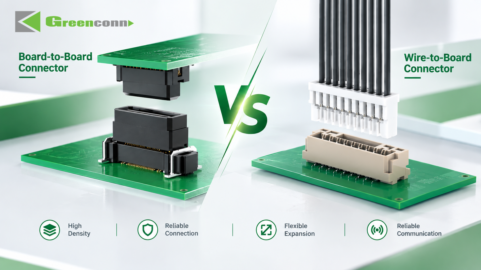
Two interconnect architectures, two different mechanical behaviours. Locking security and alignment tolerance are the criteria that separate them in most evaluations.
Why Locking and Alignment Decide the Evaluation
A PCB connector is a mechanical assembly before it is an electrical one. Every mated pair has to survive handling during assembly, thermal expansion and contraction across its operating range, and — in many products — continuous vibration. When that mechanical function is under-specified, the failure appears as an electrical symptom: intermittent power interruption, rising contact resistance, or a connection that passes first-article inspection and fails in the field.
Industry failure analysis identifies a consistent set of mechanical root causes. Locking-tab fatigue or fracture, terminal back-out, and abnormal mating or unmating forces are typical. Under vibration, reduced contact pressure can lead to intermittent power interruption, and excessive harness pulling force can pull terminals out of the housing entirely, resulting in complete loss of connection.
Alignment is the second half of the same problem. In any multi-board assembly, the actual position of each PCB after soldering and mounting is not the nominal position in the CAD file. Rigid connectors must absorb that deviation through their own contacts; connectors with a floating structure can accommodate part of it instead. Which approach is acceptable depends on how many connectors sit between the same pair of boards, how the boards are located, and whether the assembly is manual or automated.
Both criteria are mechanical, and both are typically evaluated before signal-integrity questions are settled. That is why a comparison based on locking and alignment produces a clearer architectural decision than a comparison based on pin count or price alone.
Two Architectures, Two Different Mechanical Behaviours
Wire-to-board connectors terminate a discrete wire or cable harness onto a PCB. Board-to-board connectors join two PCBs directly, with no cable in between.
The mechanical difference follows from that basic distinction. A wire-to-board connector sits between a rigid board and a flexible harness, so the harness acts as a mechanical buffer. External pulling forces on the cable are partly absorbed before they reach the solder joint, and thermal expansion differences between the board and its environment are partly taken up by the cable rather than concentrated at the connector. The trade-off is electrical: a cable harness introduces parasitic inductance and capacitance, which increases attenuation of high-frequency signals.
A board-to-board connector removes the harness, which shortens the signal path and makes impedance control and high-frequency performance more favourable. The cost is mechanical. Because the connector is mounted directly on the PCB and relies on the housing for positioning, it generally has lower resistance to insertion-related torque, and thermal expansion stresses under temperature change tend to concentrate at the connector and its solder joints rather than being distributed through a cable.
Locking Security: What Buyers Should Verify
A locking mechanism creates a mechanical retention point between the mating connector components, helping prevent unintended separation during handling, vibration, or operation. When the connector is fully mated, the locking feature engages a corresponding retention structure on the mating component. That engagement resists separation forces and holds the two halves together during normal operation. Separately, PCB retention features help secure the connector body to the board and limit movement during assembly and use.
Primary lock versus secondary lock
The distinction buyers most often under-specify is between a single-lock design and one with a secondary locking mechanism, commonly a Terminal Position Assurance (TPA) feature. A single-lock connector is simpler and more cost-effective and can be appropriate for low-vibration, static, indoor connections. Its known limitation is fatigue: after prolonged vibration the locking mechanism can loosen, contact impedance can rise, and intermittent power interruption becomes possible. Plastic embrittlement at low temperatures can further reduce locking reliability.
A TPA-equipped connector adds secondary locking that improves vibration resistance, terminal retention, and mating durability. It helps maintain stable terminal contact force, minimising contact-resistance fluctuation under vibration, and during high- and low-temperature cycling it can compensate for dimensional changes caused by plastic shrinkage.
Retention is not only about the lock
Locking performance also depends on terminal retention force, cable strain relief, and the dimensional tolerances of the mating parts. Mechanical failure risk can be reduced by optimising the locking structure, increasing terminal retention force, controlling mating force and tolerances, improving cable strain relief, and selecting materials with adequate mechanical strength. For high-vibration applications, TPA secondary locking further reduces terminal back-out. Qualification testing normally covers mating and unmating force, terminal retention, cable pull, vibration endurance, and shock.
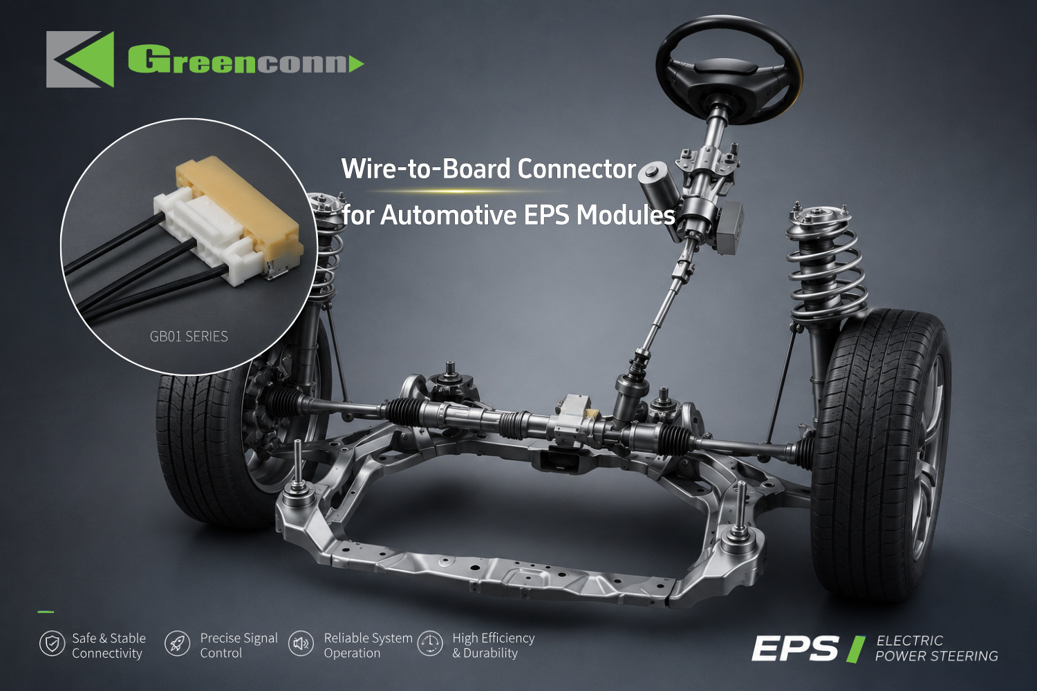
Wire-to-board connectors such as the Greenconn GB01 Series pair a 1.25 mm pitch wafer interface with harness-based mechanical buffering — relevant where cable routing and external pulling forces exist.
PCB Alignment and Floating Compensation
Floating connectors exist because real assemblies are not perfectly aligned. A floating board-to-board connector allows controlled movement in specified directions. When two PCBs are not perfectly aligned, the floating structure accommodates part of the positional deviation instead of forcing the connector contacts to absorb the entire misalignment. This reduces mating stress and improves assembly tolerance, particularly when multiple connectors are used between the same pair of PCBs.
That last condition is the one buyers most often overlook. A single connector between two boards can usually tolerate a modest amount of misalignment through normal contact compliance. Four or five connectors between the same two boards cannot — each one constrains the assembly, and the cumulative tolerance stack has to go somewhere. Floating compensation is the mechanism that gives that tolerance somewhere to go.
High-speed transmission does not remove the alignment problem
High-speed signal transmission depends on contact geometry, signal-path continuity, impedance characteristics, and the mating interface. Rigid board-to-board connections can be affected by PCB positional variation during assembly. A high-speed floating connector introduces controlled mechanical movement to accommodate that variation while maintaining a defined electrical connection between the mating contacts. The floating structure absorbs misalignment; the contact and signal-path design carries the data rate. This combination is what makes floating technology relevant for high-speed board-to-board applications where both signal performance and assembly tolerance matter.
What floating compensation does not do
Floating capability is defined movement in specified directions, not unlimited compliance. It compensates for positional variation within its designed range. It does not replace correct PCB locating features, it does not correct a tolerance stack that exceeds the connector's rated range, and it does not eliminate the need to define the mating height in the assembly. Buyers should treat floating range as a specified parameter to be matched to the measured assembly tolerance, not as a general-purpose margin.
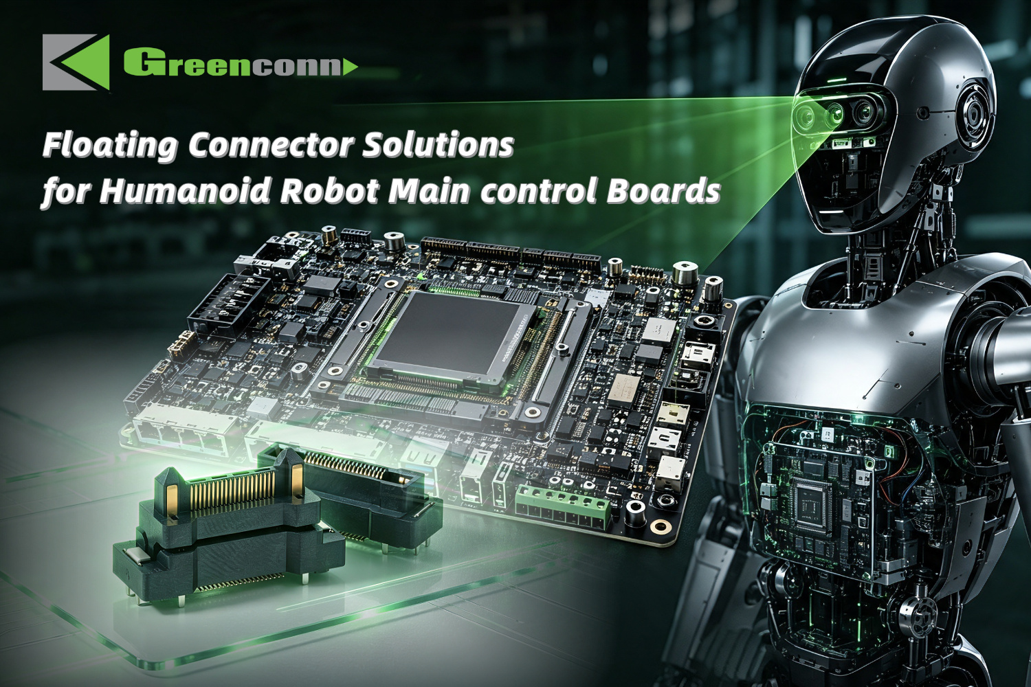
Board-to-board floating connectors such as the Greenconn GC01 Series use a floating compensation structure to absorb PCB positional variation in multi-board control architectures.
Side-by-Side Comparison
The table below compares the two architectures on the criteria that matter in a locking-and-alignment evaluation. It is a structural comparison of connector types, not a recommendation of one over the other.
| Evaluation criterion | Wire-to-board connector | Board-to-board connector |
|---|---|---|
| Mechanical buffering | Harness provides mechanical buffering | Housing positioning only; no cable buffer |
| Resistance to external pulling force | Better resistance to external pulling forces | Lower; force transmits directly to the mated pair |
| Signal path length | Longer; harness adds parasitic inductance and capacitance | Shorter signal path |
| High-frequency behaviour | Greater attenuation of high-frequency signals | Impedance control and high-frequency performance more favourable |
| Thermal cycling stress | Harness absorbs and releases thermal expansion stress | Thermal expansion stresses concentrate at the connector and solder joints |
| Insertion torque resistance | Higher, due to harness compliance | Generally lower; relies on the housing for positioning |
| Alignment approach | Cable routing flexes; connector-to-board interface is rigid | Floating structure can be specified for X/Y/Z compensation |
| Typical locking provisions | Locking structure plus optional TPA secondary lock | Housing retention plus floating compensation design |
| Packaging density | Occupied by connector plus cable routing space | More compact; no cable routing volume |
Matching the Architecture to the Application
Neither type is universally superior. The decision usually resolves to a short set of application conditions.
Where wire-to-board connectors fit
- Cable harness routing is part of the design. Where the connection has to bridge a moving assembly, a door, a panel, or a distance between subsystems, the harness is doing work that a board-to-board connector cannot do.
- External pulling forces are expected. The harness-based architecture tolerates pulling and movement better, because the cable absorbs part of the force before it reaches the solder joint.
- Thermal cycling is a dominant stress. The harness can absorb and release thermal expansion stress, which gives wire-to-board connections better resistance to temperature-change cycling.
- Locking security is the primary requirement. Applications requiring secure mating and reliable PCB retention can use a locking structure, with vertical and right-angle configurations available to suit different PCB layouts and installation requirements.
Where board-to-board connectors fit
- Signal frequency is high and the path is short. Board-to-board interconnects are the natural choice for high-frequency signal interconnection within and between PCBs, because the shorter signal path supports impedance control.
- Multiple connectors sit between the same boards. This is where floating compensation earns its place. The tolerance stack across several connectors is what forces the misalignment into the contacts if no floating structure exists.
- Space is constrained. Eliminating the harness removes cable routing volume and allows a more compact layout.
- Both power and signal travel between boards. Combined signal-and-power contact designs allow one connector to carry both, which reduces part count in multi-board architectures.
In practice, many products use both. A humanoid robot joint module may use a 1.25 mm pitch wire-to-board interface where the joint moves and a floating board-to-board interface between the control boards that must stay aligned. The architecture decision is made per connection, not per product.
Supplier Capability: What OEM Buyers Should Screen For
Once the architecture is chosen, the evaluation shifts from connector type to supplier capability. For custom and semi-custom interconnect programmes, four capability areas tend to determine whether a supplier can support the project through prototyping and into volume production.
Customisation scope
A supplier's customisation list should be specific enough to map onto the design requirements. Greenconn, a connector manufacturer established in 1998 and operating four manufacturing facilities across China and Vietnam, lists customisation across voltage, current, pin count, contact resistance, high-speed data rate, pitch, mounting type, locking mechanism, floating range, stacking height, overall dimensions, IP rating, housing material, contact material, plating thickness, contact plating, and overmolding material. Both OEM and ODM service models are available.
That list matters because locking and alignment requirements are rarely satisfiable from a catalogue alone. A floating range that matches a measured tolerance stack, or a locking mechanism sized for a specific vibration profile, is normally a custom or configured variant rather than a standard part number.
Process integration
Where a supplier owns tooling, stamping, plating, injection moulding, and automated assembly in-house, changes to a locking geometry or a floating structure do not depend on an external tooling supplier's schedule. Greenconn states that its production is vertically integrated across design, tooling manufacturing, stamping, plating, injection moulding, and automation, with engineering capability covering product development, prototyping, validation, and mass production, supported by an R&D team of 69 engineers.
Volume, lead time, and quality control
For programmes moving from evaluation into execution, three commercial parameters define the ramp: capacity, lead time, and inspection regime. Greenconn's stated monthly capacity is 28,750,000 pcs, with a typical production lead time of 4 weeks and a minimum order quantity of 5000. Quality control is described as AQL sampling inspection, with after-sales support through local dealers and offices. For buyers building a launch schedule, the 4-week lead time is the parameter that most directly constrains how late a connector change can be introduced.
Certification coverage
Certification requirements depend on the end market. Greenconn maintains quality and environmental management systems certified to ISO 9001 (certificate 030825002C, valid to 2028-08-17), ISO 14001 (111121007/1C, valid to 2027-11-28), ISO 45001 (450224015, valid to 2027-02-27), and IATF 16949 (160319060-2, valid to 2029-04-02), with ISO 13485 (G25Q2GZ1104R0S, valid to 2028-01-01) covering design and production of electronic connectors for specified medical device applications. Buyers should confirm that the certificate scope covers the specific site and product family in their programme, rather than treating company-level certification as product-level approval.
Market Context: Why This Comparison Matters Now
Two structural trends are pushing both connector architectures into more demanding roles at the same time.
The first is scale. The global PCB connector market was estimated at USD 33.83 billion in 2025, with a projected path to USD 47.96 billion by 2035. Within that market, board-to-board connectors were the largest single connector type in 2025, at approximately 24.3% revenue share (USD 4,459.8 million). That concentration means the locking and alignment behaviour of board-to-board interfaces affects a large share of design decisions.
The second is application-driven. Board-to-board connectors have been discussed in the industry as important components in the automation and Industrial IoT applications associated with Industry 4.0. In parallel, the automotive connector market — a segment with some of the strictest locking and vibration requirements — was valued at USD 6.82 billion in 2025 and is projected to reach USD 11.39 billion by 2033, driven in part by EV and ADAS architectures. USCAR-2, the performance standard for low-voltage automotive electrical connector systems, defines the testing regime that automotive-grade connectors are measured against.
The combined effect is that more designs now sit between the two categories: high-speed board-to-board signal paths that also have to survive vibration, and wire-to-board power connections that also have to survive temperature cycling. Buyers who evaluate only one of the two mechanical criteria tend to discover the other during validation.
Limits and Boundaries of Each Option
Both architectures carry constraints that should be stated before a selection is locked in.
Wire-to-board: the harness that provides mechanical buffering also introduces parasitic inductance and capacitance. Where signal frequency rises, that attenuation becomes the limiting factor, and the connector may cease to be a viable option regardless of how good its locking behaviour is. Harness routing also consumes board and enclosure volume, and adds an assembly step that must be controlled for correct cable seating.
Board-to-board: removing the harness removes the buffer. External pulling forces and insertion torque act more directly on the mated pair and the solder joints, and thermal expansion stress concentrates at the connector rather than being distributed through a cable. Floating compensation addresses positional variation within its specified range only — it is not a substitute for correct board locating features, and it does not resolve a tolerance stack that exceeds the rated range. Where multiple connectors share the same board pair, the tolerance budget has to be allocated across them deliberately.
Shared constraint: locking performance depends on the whole retention system, not on the locking feature alone. A well-designed lock paired with inadequate terminal retention force, insufficient cable strain relief, or loose dimensional tolerances will still fail under vibration. Any qualification plan should test the mated system, not the lock in isolation.
Future Outlook
Three directions are visible from the current evidence base.
Convergence of high-speed and floating requirements. As automation, robotics, and automotive electronics push more data across board-to-board interfaces, designs increasingly need both signal performance and alignment tolerance in the same connector. Floating high-speed board-to-board connectors — with specified floating movement alongside a defined data rate and contact geometry — are the product category this trend produces.
Rising minimum locking requirements. Where vibration environments are severe and temperature ranges are wide, TPA secondary locking is becoming the baseline expectation rather than an upgrade. Buyers specifying single-lock connectors for those conditions should expect to justify the decision during validation.
Earlier supplier involvement. Because floating range, stacking height, and locking geometry often have to be matched to measured assembly tolerances, and because tooling changes affect lead time, the point at which a connector supplier enters a programme is shifting earlier. Suppliers able to move from design and prototyping through to volume manufacturing within a single integrated process reduce the risk of a late mechanical redesign.
FAQ
How should I choose between board-to-board and wire-to-board connectors?
The decision turns on signal frequency and mechanical protection. Board-to-board connectors offer a more compact design, rely on the housing for positioning, generally have lower resistance to insertion-related torque, and provide a shorter signal path, which makes impedance control and high-frequency performance more favourable; however, because they mount directly on the PCB, thermal expansion stresses tend to concentrate under temperature changes. Wire-to-board connectors provide harness-based mechanical buffering and better resistance to external pulling forces, but the harness introduces parasitic inductance and capacitance, which causes greater attenuation of high-frequency signals, while also absorbing and releasing thermal expansion stress. A common evaluation rule is to choose board-to-board for high-frequency signal interconnection within and between PCBs, and wire-to-board where cable harness routing, mechanical movement, or external pulling forces are involved.
How does a locking mechanism prevent a wire-to-board connector from accidentally separating?
A locking mechanism creates a mechanical retention point between the mating connector components, helping prevent unintended separation during handling, vibration, or operation. When the connector is fully mated, the locking feature engages a corresponding retention structure on the mating component; that engagement resists separation forces and helps keep the connector halves together during normal operation. PCB retention features additionally help secure the connector to the board and limit movement during assembly and use. Actual retention performance depends on the connector design, the mating condition, and the application environment.
How does a floating board-to-board connector compensate for PCB misalignment?
Unlike a fixed board-to-board connector, a floating connector allows controlled movement in specified directions. When two PCBs are not perfectly aligned, the floating structure can accommodate part of the positional deviation instead of forcing the connector contacts to absorb the entire misalignment. This helps reduce mating stress and improves assembly tolerance, particularly when multiple connectors are used between the same PCBs. Floating capability is defined movement within a designed range, not unlimited compliance, so the floating range should be matched to the measured assembly tolerance.
How can a high-speed board-to-board connector accommodate PCB alignment tolerances without compromising signal transmission?
A high-speed floating connector combines controlled mechanical movement with a carefully designed signal path. High-speed signal transmission depends on factors such as contact geometry, signal-path continuity, impedance characteristics, and the mating interface, while rigid board-to-board connections can be affected by PCB positional variation during assembly. The floating structure introduces controlled mechanical movement to accommodate that variation while maintaining a defined electrical connection between the mating contacts. This combination makes floating technology useful for high-speed board-to-board applications where both signal performance and assembly tolerance are important.
What failures can occur when the mechanical performance of a connector is inadequate?
Potential failures include locking-tab fatigue or fracture, terminal back-out, and abnormal mating or unmating forces. Under vibration conditions, reduced contact pressure can lead to intermittent power interruption, and excessive cable-harness pulling force may pull terminals out of the housing, resulting in complete loss of electrical connection. Mechanical failure risk can be reduced by optimising the locking structure, increasing terminal retention force, controlling mating force and dimensional tolerances, improving cable strain relief, and selecting materials with adequate mechanical strength. For high-vibration applications, TPA secondary locking can further reduce terminal back-out, and qualification testing typically covers mating and unmating force, terminal retention, cable pull, vibration endurance, and shock testing.
For detailed product families, pitches, and configuration options across board-to-board, wire-to-board, floating, high-speed, waterproof, and custom connector solutions, the Greenconn Introduction Brochure is available for download.
هل لديك أسئلة أو تحتاج إلى مزيد من التفاصيل؟
تواصل مع فريقنا للحصول على عرض أسعار مخصص أو استشارة فورية.
طلب عرض أسعار
املأ النموذج أدناه وسيتواصل معك فريقنا بعرض مقترح مخصص.
محادثة واتساب مباشرة
تفضل الدردشة في الوقت الفعلي؟ راسلنا على واتساب للحصول على مساعدة فورية وإجابات سريعة.
- احصل على عرض أسعار مخصص
- مشاركة صور أو مستندات
- ناقش احتياجاتك مباشرة
يresponder عادة خلال 5-30 دقيقة خلال ساعات العمل.