حول Apex Hydraulic
With a 50,000 m² manufacturing facility, 500+ employees, and an annual production capacity of 100,000 hydraulic cylinders and 15,000 power units, APEX Hydraulic provides OEM and ODM manufacturing services for equipment manufacturers, hydraulic distributors, and hydraulic solution providers worldwide.
Our products are widely used in sanitation vehicles, dump trailers, dump trucks, roll-off trucks, agricultural machinery, construction equipment, mining machinery, marine equipment, material handling equipment, and other mobile hydraulic applications.
Supported by an experienced engineering and R&D team, in addition to offering standard hydraulic cylinder models that are popular in the North American and European markets, we also provide complete customization services, including product design, engineering drawings, prototype development, testing, manufacturing, and quality inspection. Every hydraulic cylinder and hydraulic power unit is manufactured under strict quality control to ensure reliable performance, long service life, and stable operation under demanding working conditions.
Today, APEX Hydraulic exports to customers across North America, Europe, Australia, Southeast Asia, the Middle East, and South America, building long-term partnerships with OEM manufacturers, distributors, and industrial equipment companies through quality, technical expertise, and responsive customer service.
منتجاتنا
عرض جميع المنتجات ← →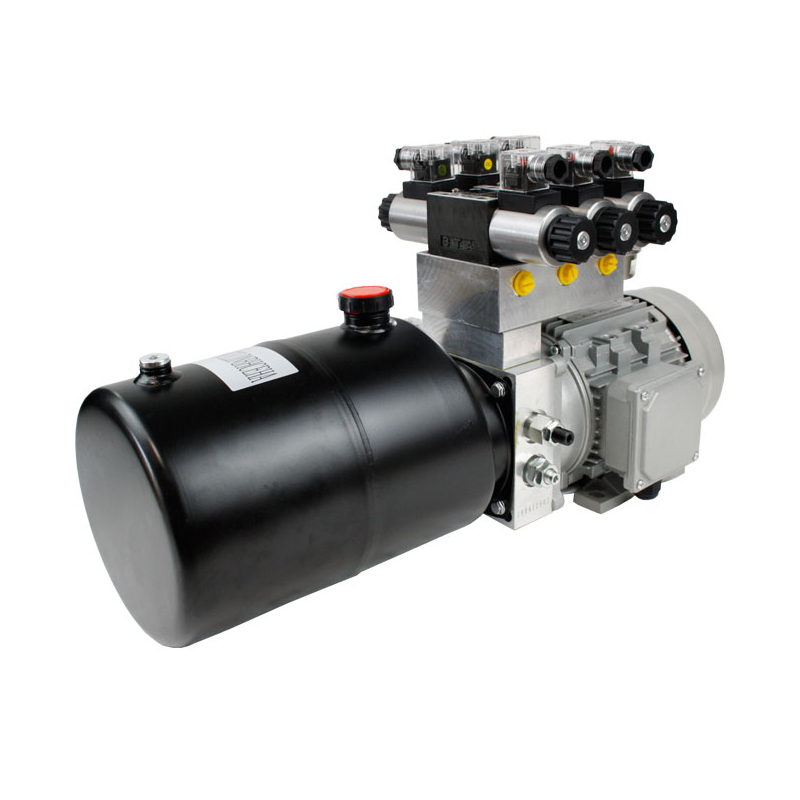
Custom Low-Noise Compact Hydraulic Power Unit
الموديل: APEX-CLNCHPU
المعلمات: System Type: Single-Acting / Double-Acting / Reversible Pump System
Hydraulic Functions: 1–4 Functions
Rated DC Voltage: 12 VDC / 24 VDC / 48 VDC
Rated AC Voltage: 220 VAC / 380 VAC
Rated Frequency: 50 Hz / 60 Hz
Motor Power: 0.35–4.0 kW
Motor Duty: Intermittent Duty / Continuous Duty
Motor Type: Brushed DC Motor / Brushless DC Motor / AC Induction Motor
Pump Type: Low-Noise External Gear Pump
Pump Direction: Unidirectional / Reversible
Pump Displacement: 0.25–10.0 cm³/rev
Flow Rate: 1–20 L/min
Maximum Working Pressure: 230 bar / 3,335 PSI
Reservoir Capacity: 0.5–18 L
Reservoir Material: Steel / Aluminum / Polymer
Reservoir Installation: Horizontal / Vertical
Directional Valve Type: 2-Way / 3-Way / 4-Way
Valve Control: Manual / Solenoid / Proportional
Directional Valve Mounting: Integrated Manifold / Modular Valve Block
Solenoid Voltage: 12 VDC / 24 VDC / 48 VDC / 110 VAC / 220 VAC
Control Method: Push Button / Foot Pedal / Wired Pendant / Wireless Remote / PLC
Power Up / Gravity Down: Available
Power Up / Power Down: Available
Reversible Pump Control: Available
Pressure Relief Valve: Adjustable
Pressure Reducing Valve: Optional
Pressure-Compensated Flow Control Valve: Optional
Proportional Flow Control Valve: Optional
Pilot-Operated Check Valve: Optional
Load-Holding Valve: Optional
Counterbalance Valve: Optional
Hydraulic Accumulator: Optional
Manual Emergency Lowering: Optional
Emergency Hand Pump: Optional
Return-Line Filter: Optional
Suction Strainer: Optional
Air Breather Filter: Optional
Oil Level Indicator: Optional
Oil Temperature Sensor: Optional
Pressure Sensor: Optional
Anti-Vibration Mounts: Optional
Acoustic Enclosure: Optional
Flexible Motor-Pump Coupling: Optional
Hydraulic Ports: SAE ORB / NPT / BSPP / Metric
Port Size: SAE #4–#10 / 1/4–5/8 Inch
Hydraulic Fluid Temperature: −20°C to +80°C
Recommended Hydraulic Fluid: ISO VG 22 / ISO VG 32 / ISO VG 46
Fluid Cleanliness Level: ISO 4406 20/18/15
Cooling Method: Natural Air Cooling / Forced-Air Cooling
Installation Type: Machine-Mounted / Wall-Mounted / Floor-Mounted / Cabinet-Mounted
Ingress Protection: IP54 / IP55 / IP65
Custom Hydraulic Manifold: Available
Custom Electrical Control: Available
OEM / ODM Service: Available
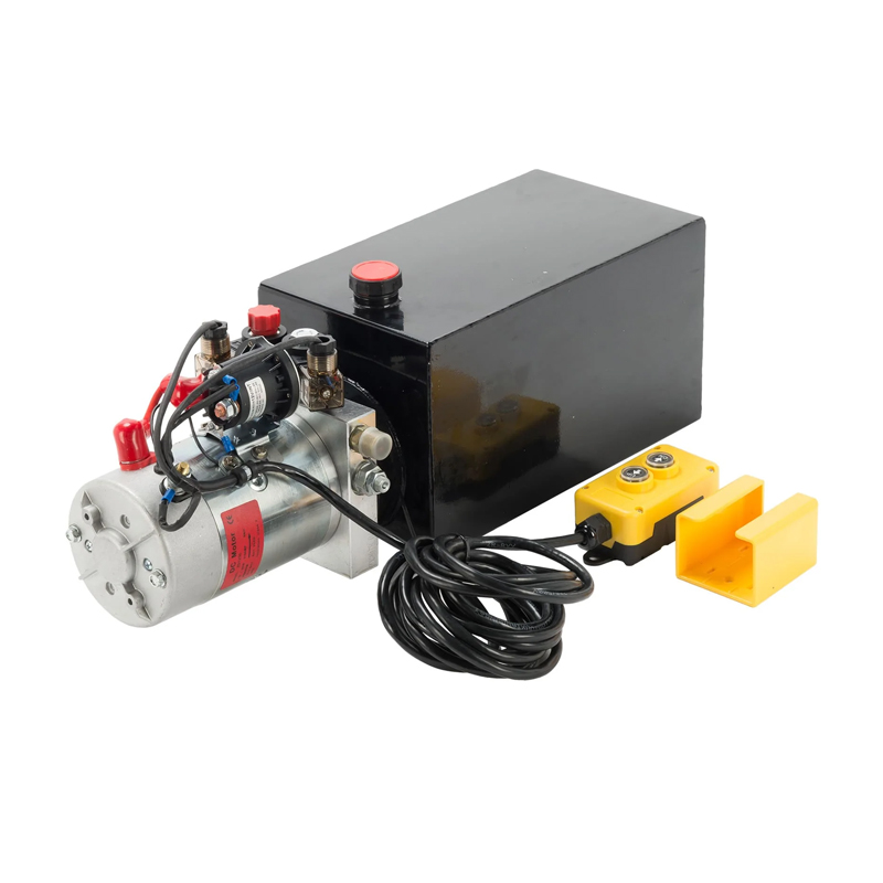
Custom Vehicle-Mounted Auxiliary Hydraulic Power Unit
الموديل: APEX-CVMAHPU
المعلمات: System Type: Single-Acting / Double-Acting / Combined System
Hydraulic Functions: 1–6 Functions
Rated Voltage: 24 VDC / 48 VDC
Motor Power: 1.5–8.0 kW
Motor Duty: Intermittent Duty / Continuous Duty
Motor Type: Brushed DC Motor / Brushless DC Motor
Pump Type: High-Pressure External Gear Pump
Pump Direction: Unidirectional / Reversible
Pump Displacement: 1.2–26.2 cm³/rev
Flow Rate: 3–40 L/min
Maximum Working Pressure: 250 bar / 3,625 PSI
Reservoir Capacity: 5–60 L
Reservoir Material: Steel / Aluminum
Reservoir Installation: Horizontal / Vertical / Chassis-Mounted
Directional Valve Type: 2-Way / 3-Way / 4-Way
Valve Control: Solenoid / Manual / Proportional
Solenoid Voltage: 24 VDC / 48 VDC
Control Method: Cab-Mounted Switch / Wired Pendant / Wireless Remote / PLC / CAN Bus
Main Power Function: Available
Emergency Auxiliary Function: Available
Power Up / Gravity Down: Available
Power Up / Power Down: Available
Independent Multi-Function Control: Available
Pressure Relief Valve: Adjustable
Pressure-Compensated Flow Control Valve: Optional
Load-Holding Valve: Optional
Counterbalance Valve: Optional
Pilot-Operated Check Valve: Optional
Hydraulic Lock: Optional
Manual Emergency Lowering: Optional
Emergency Hand Pump: Optional
Return-Line Filter: Optional
Pressure-Line Filter: Optional
Suction Strainer: Optional
Oil Cooler: Optional
Oil Heater: Optional
Oil Level Indicator: Optional
Oil Temperature Sensor: Optional
Pressure Sensor: Optional
Hydraulic Ports: SAE ORB / NPT / BSPP / Metric
Port Size: SAE #6–#16 / 3/8–1 Inch
Hydraulic Fluid Temperature: −20°C to +80°C
Recommended Hydraulic Fluid: ISO VG 32 / ISO VG 46
Fluid Cleanliness Level: ISO 4406 20/18/15
Installation Type: Chassis-Mounted / Frame-Mounted / Enclosure-Mounted
Ingress Protection: IP54 / IP65 / IP66
Weather-Resistant Enclosure: Optional
Custom Hydraulic Manifold: Available
Custom Wiring Harness: Available
OEM / ODM Service: Available
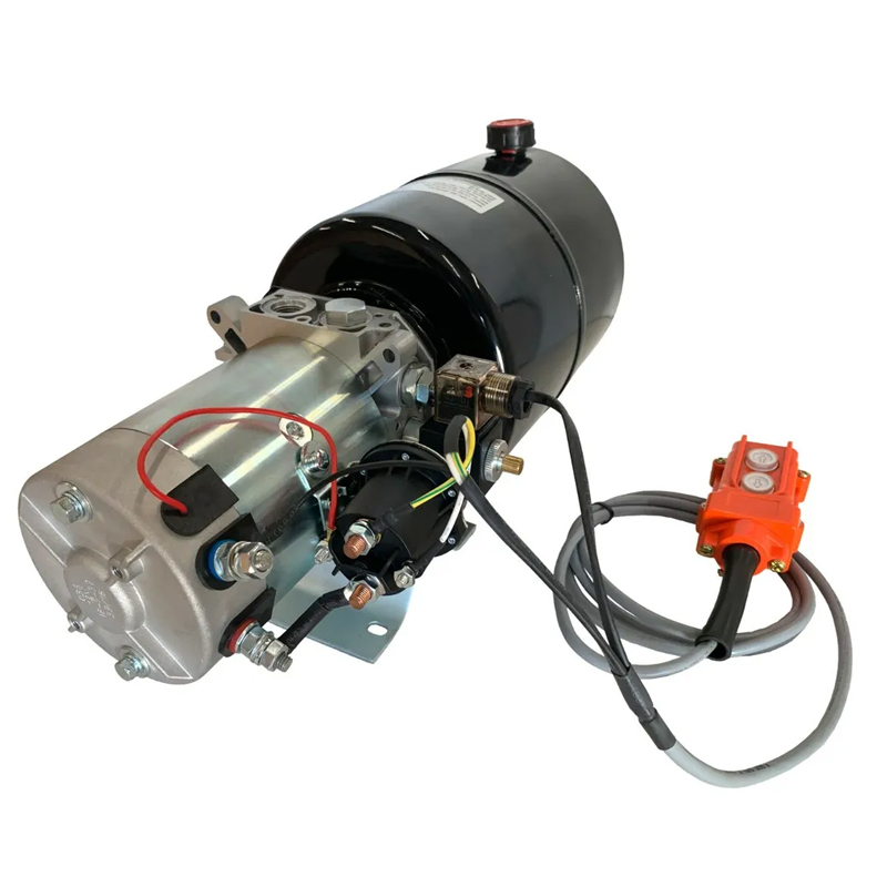
Custom AC Industrial Hydraulic Power Unit
الموديل: APEX-ACHPU Series
المعلمات: System Type: Single-Acting / Double-Acting / Multi-Actuator System
Rated Voltage: 220 VAC / 380 VAC
Electrical Phase: Single Phase / Three Phase
Rated Frequency: 50 Hz / 60 Hz
Motor Power: 0.12–4.0 kW
Motor Duty: Intermittent Duty / Continuous Duty
Motor Type: TEFC AC Induction Motor
Pump Type: External Gear Pump
Pump Displacement: 0.25–10.0 cm³/rev
Flow Rate: 1.5–30 L/min
Maximum Working Pressure: 230 bar / 3,335 PSI
Reservoir Capacity: 1.5–18 L
Reservoir Material: Steel / Aluminum
Reservoir Installation: Horizontal / Vertical
Valve Control: Manual / Solenoid / Proportional
Directional Valve Type: 2-Way / 3-Way / 4-Way
Directional Valve Mounting: Integrated Manifold / CETOP Modular Valve Block
Number of Hydraulic Functions: 1–8 Functions
Solenoid Voltage: 12 VDC / 24 VDC / 110 VAC / 220 VAC
Control Interface: Push Button / Foot Pedal / PLC / HMI / Remote Control
Pressure Relief Valve: Adjustable
Pressure Reducing Valve: Optional
Flow Control Valve: Optional
Proportional Pressure Control: Optional
Proportional Flow Control: Optional
Pilot-Operated Check Valve: Optional
Counterbalance Valve: Optional
Hydraulic Accumulator: Optional
Oil Cooler: Optional
Oil Heater: Optional
Return-Line Filter: Optional
Pressure-Line Filter: Optional
Suction Strainer: Optional
Air Breather Filter: Optional
Oil Level Indicator: Optional
Oil Temperature Gauge: Optional
Pressure Gauge: Optional
Pressure Sensor: Optional
Temperature Sensor: Optional
Oil Level Sensor: Optional
Hydraulic Ports: SAE ORB / NPT / BSPP / Metric
Hydraulic Fluid Temperature: −20°C to +80°C
Recommended Hydraulic Fluid: ISO VG 32 / ISO VG 46 / ISO VG 68
Fluid Cleanliness Level: ISO 4406 20/18/15
Cooling Method: Natural Air Cooling / Forced-Air Oil Cooling
Installation Type: Floor-Mounted / Machine-Mounted / Wall-Mounted
Electrical Protection: IP54 / IP55 / IP65
Custom Hydraulic Manifold: Available
Custom Electrical Control Cabinet: Available
OEM / ODM Service: Available
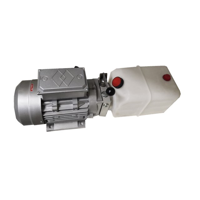
Custom Multi-Function Hydraulic Power Unit for Aerial Work Platforms
الموديل: APEX-CMFHPU
المعلمات: Hydraulic Functions: 2–8 Functions
System Type: Single-Acting / Double-Acting / Combined System
Rated Voltage: 12 VDC / 24 VDC / 48 VDC
Motor Power: 0.8–4.0 kW
Motor Duty: Intermittent Duty / Continuous Duty
Standard Intermittent Duty Cycle: 1 Minute On-Load / 9 Minutes Off-Load
Pump Type: High-Pressure External Gear Pump
Pump Configuration: Single Gear Pump / Double Gear Pump
Pump Displacement: 0.8–10.0 cm³/rev
Flow Rate: 1.5–30 L/min
Maximum Working Pressure: 280 bar / 4,000 PSI
Reservoir Capacity: 1.5–18 L
Reservoir Installation: Horizontal / Vertical
Reservoir Material: Steel / Aluminum / Polymer
Directional Valve Type: 2-Way / 3-Way / 4-Way Solenoid Valve
Directional Valve Configuration: Monoblock / Modular Manifold
Solenoid Voltage: 12 VDC / 24 VDC / 48 VDC
Control Method: Wired Pendant / Wireless Remote / Joystick / PLC / CAN Bus
Main Power Unit Function: Available
Emergency Auxiliary Power Function: Available
Electric Lifting Function: Available
Hydraulic Steering Function: Available
Platform Leveling Function: Available
Outrigger Control Function: Available
Emergency Lowering Function: Available
Manual Emergency Lowering: Optional
Manual Emergency Hand Pump: Optional
Pressure Relief Valve: Adjustable
Pressure-Compensated Flow Control Valve: Optional
Load-Holding Valve: Optional
Counterbalance Valve: Optional
Pilot-Operated Check Valve: Optional
Hydraulic Lock: Optional
Return-Line Filter: Optional
Suction Strainer: Optional
Oil Level Indicator: Optional
Oil Temperature Sensor: Optional
Pressure Sensor: Optional
Hydraulic Ports: SAE ORB / NPT / BSPP / Metric
Port Size: SAE #6–#12 / 3/8–3/4 Inch
Hydraulic Fluid Temperature: −20°C to +80°C
Recommended Hydraulic Fluid: ISO VG 32 / ISO VG 46
Fluid Cleanliness Level: ISO 4406 20/18/15
Installation Position: Horizontal / Vertical / Vehicle-Mounted
Ingress Protection: IP54 / IP65 / IP66
Custom Hydraulic Manifold: Available
Custom Wiring Harness: Available
OEM / ODM Service: Available
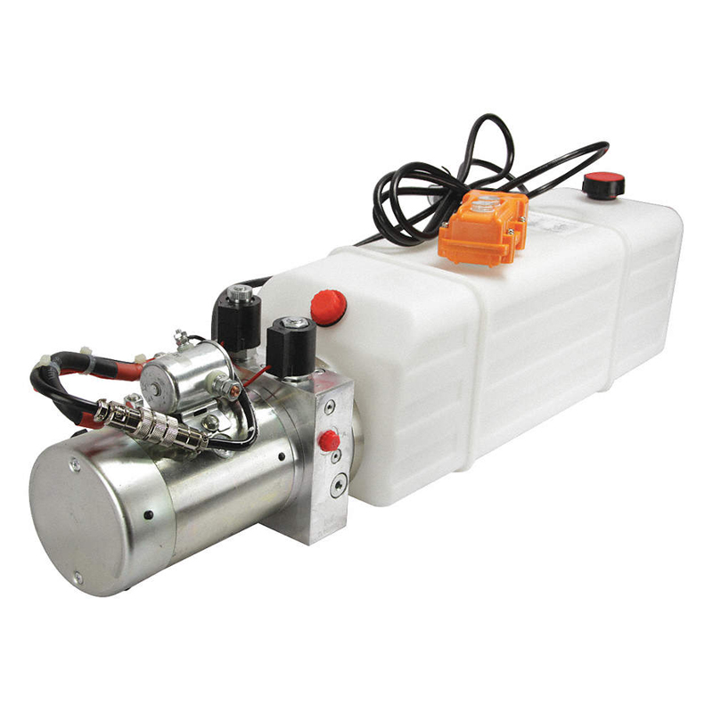
Custom Double-Acting Mobile Hydraulic Power Unit
الموديل: APEX-CDAMHPU
المعلمات: Operating Type: Double Acting
Hydraulic Function: Power Up / Power Down
Rated Voltage: 12 VDC / 24 VDC / 48 VDC
Motor Power: 0.35–3.0 kW
Motor Duty: Intermittent Duty / Continuous Duty
Pump Type: High-Pressure External Gear Pump
Pump Displacement: 0.25–10.0 cm³/rev
Flow Rate: 1.5–30 L/min
Maximum Working Pressure: 280 bar / 4,000 PSI
Reservoir Capacity: 0.9–18 L
Reservoir Installation: Horizontal / Vertical
Reservoir Material: Steel / Aluminum / Polymer
Directional Control: 4-Way 2-Position / 4-Way 3-Position Solenoid Valve
Center Configuration: Closed Center / Tandem Center / Float Center
Solenoid Voltage: 12 VDC / 24 VDC / 48 VDC
Control Method: Wired Pendant / Wireless Remote / Vehicle-Mounted Switch / PLC Signal
Pendant Configuration: 2-Button / 3-Button / 4-Button
Hydraulic Ports: SAE ORB / NPT / BSPP / Metric
Port Size: SAE #6–#10 / 3/8–3/4 Inch
Pressure Relief Valve: Adjustable
Flow Control Valve: Optional
Load-Holding Valve: Optional
Pilot-Operated Check Valve: Optional
Counterbalance Valve: Optional
Manual Emergency Lowering: Optional
Hand Pump Backup: Optional
Oil Level Indicator: Optional
Oil Temperature Sensor: Optional
Return Filter: Optional
Suction Strainer: Optional
Hydraulic Fluid Temperature: −20°C to +80°C
Recommended Hydraulic Fluid: ISO VG 32 / ISO VG 46
Installation Position: Horizontal / Vertical / Vehicle-Mounted
Ingress Protection: IP54 / IP65 / IP66
Custom Hydraulic Manifold: Available
OEM / ODM Service: Available
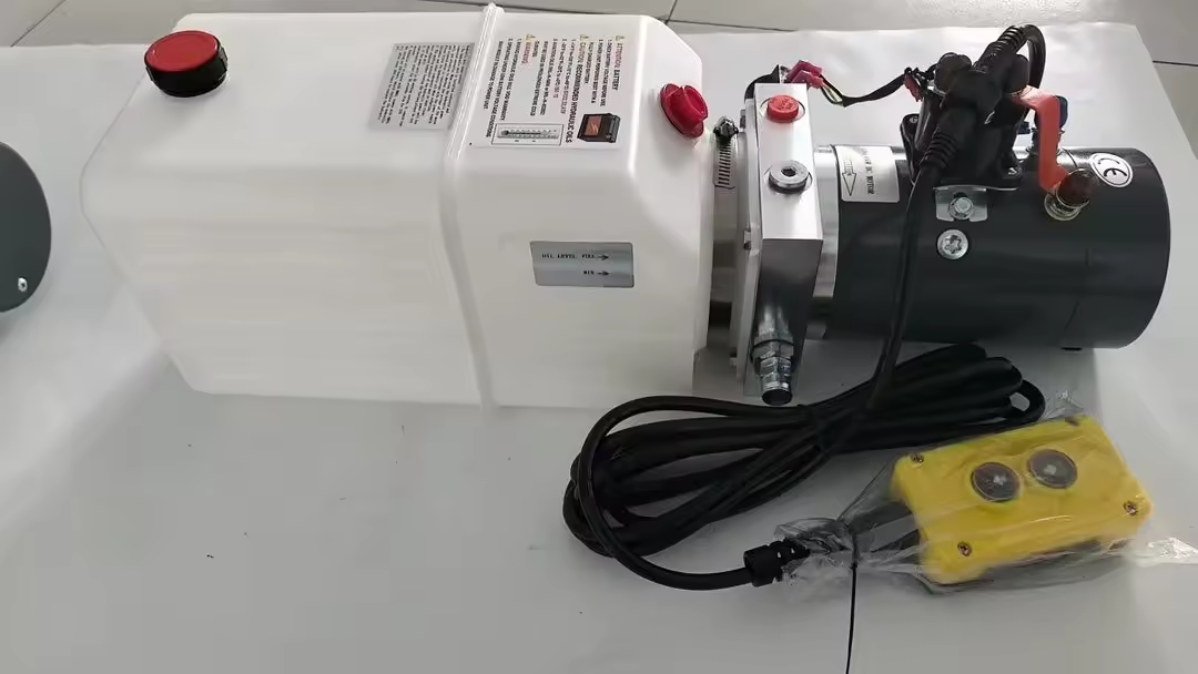
12V DC Dump Trailer Hydraulic Power Unit
الموديل: APEX-DTHPU
المعلمات: System Type: Power Up / Gravity Down
Compatible Cylinder Type: Single-Acting Hydraulic Cylinder
Compatible Telescopic Cylinder: HTC-Series Dump Trailer Telescopic Cylinder
Motor Voltage: 12 VDC
Motor Type: Intermittent-Duty DC Motor
Reservoir Capacity: 6 US Quarts
Reservoir Type: Translucent Horizontal-Mount Reservoir
Hydraulic Pump Type: High-Pressure Gear Pump
Maximum Hydraulic Flow Rate: 2.0 GPM
Maximum Relief Setting at A Port: 3,200 PSI
Maximum Relief Setting at B Port: 1,500 PSI
Hydraulic Port Type: SAE #6
Mounting Orientation: Horizontal
Lifting Function: Electric-Motor-Driven Hydraulic Extension
Lowering Function: Solenoid-Controlled Gravity Return
Control Type: Two-Button Handheld Pendant
Pendant Functions: UP and DOWN
Pendant Cord Length: 15 ft
Pendant Connection: Removable Cord
Motor Control: Start Solenoid
Lowering Valve: Normally Closed Solenoid Valve
Pressure Relief Valve: Integrated
Flow-Control Valve: Integrated or application-specific lowering-flow control
Check Valve: Integrated load-retention check valve
Hydraulic Circuit: Single-Acting Power-Up / Gravity-Down Circuit
Hydraulic Fluid: Automatic Transmission Fluid or compatible hydraulic oil selected according to temperature
Duty Cycle: Intermittent Duty
Operating Environment: Mobile and Outdoor Trailer Equipment
Electrical Connection: Battery Cables Connected to a 12V Trailer Battery
Remote-Control Option: Wired Pendant Standard
Wireless Remote Control: Optional
Manual Emergency Lowering: Optional
Reservoir Options: 3, 4, 6, 8 and 13 US Quarts
Motor-Power Options: Selected according to pressure, flow and duty-cycle requirements
Pump-Displacement Options: Selected according to required lifting speed
Pressure Setting: Adjustable according to the approved hydraulic system within the rated component limits
Hydraulic Hose: Selected according to working pressure, length and port configuration
Mounting Bracket: Optional
Weather-Protection Cover: Optional
Battery Charger: Optional
Battery-Isolator Switch: Optional
Identification: Customer Logo, Part Number, Serial Number and Traceability Label Available
Testing: Pressure Testing
Testing: Flow Testing
Testing: Relief-Valve Verification
Testing: Solenoid-Valve Functional Testing
Testing: Motor Current Testing
Testing: Leakage Inspection
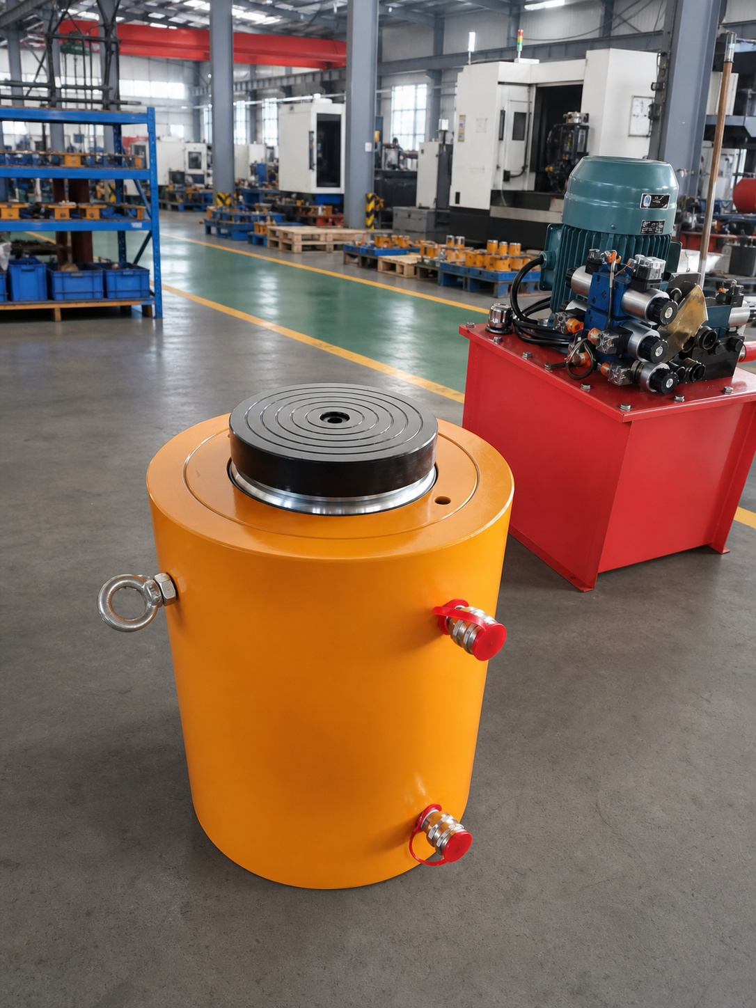
Custom Single-Acting Ram / Plunger Hydraulic Cylinder
الموديل: APEX-CSPC Series
المعلمات: Cylinder Structure: Single-acting ram, plunger or piston-type construction
Acting Type: Single Acting
Bore / Plunger Diameter: 50–400 mm
Guide Diameter: 40–380 mm
Stroke Length: 50–2,500 mm
Working Pressure: 160–350 bar
Maximum Design Pressure: Up to 500 bar for specially engineered configurations
Operating Temperature: -20°C to +80°C
Extended Temperature Range: -40°C to +120°C with application-specific seals and materials
Operating Speed: 5–300 mm/s
Hydraulic Medium: Mineral-based hydraulic oil or approved compatible fluid
Output Force: Calculated according to effective pressure area and working pressure
Return Method: Gravity Return
Return Method: External Load Return
Return Method: Spring Return
Return Method: Mechanical Linkage Return
Return Force: Determined by gravity, external load, spring force or equipment mechanism
Minimum Return Load: Defined according to seal friction, guide friction and installation orientation
Installation Direction: Primarily vertical or inclined; horizontal installation requires engineering review
Plunger Stability: Verified according to unsupported length, load and installation direction
Side-Load Condition: External guides are recommended where significant side loading may occur
Stroke-to-Diameter Ratio: Determined according to stability and application requirements
Retracted Length: Customized according to stroke and installation envelope
Extended Length: Retracted length plus effective stroke
Plunger-End Style: Flat saddle, threaded end, spherical saddle, pin-eye, clevis or custom interface
Base Mounting: Flange, foot mount, trunnion, clevis, threaded body or custom mounting
Hydraulic Port: SAE ORB, NPT, BSPP, metric thread, SAE flange or customer-specified connection
Port Position: Side, bottom, rear or customer-specified orientation
Air-Bleed Port: Optional according to installation direction
Overflow / Vent Arrangement: Optional according to cylinder construction
Load-Holding Valve: Optional pilot-operated check valve or hose-burst valve
Mechanical Locking: Optional lock nut, locking collar, support ring or external mechanical support
Overtravel Protection: Optional internal stop or external mechanical stop provision
Position Sensing: Optional proximity switch, stroke switch or external linear sensor
Plunger Protection: Optional bellows, protective sleeve or heavy-duty scraper system
Surface Protection: Industrial paint, powder coating, zinc-based coating or corrosion-resistant treatment
Identification: Customer part number, serial number, logo and traceability code available
Testing: Dimensional inspection, pressure testing, leakage testing and full-stroke functional testing
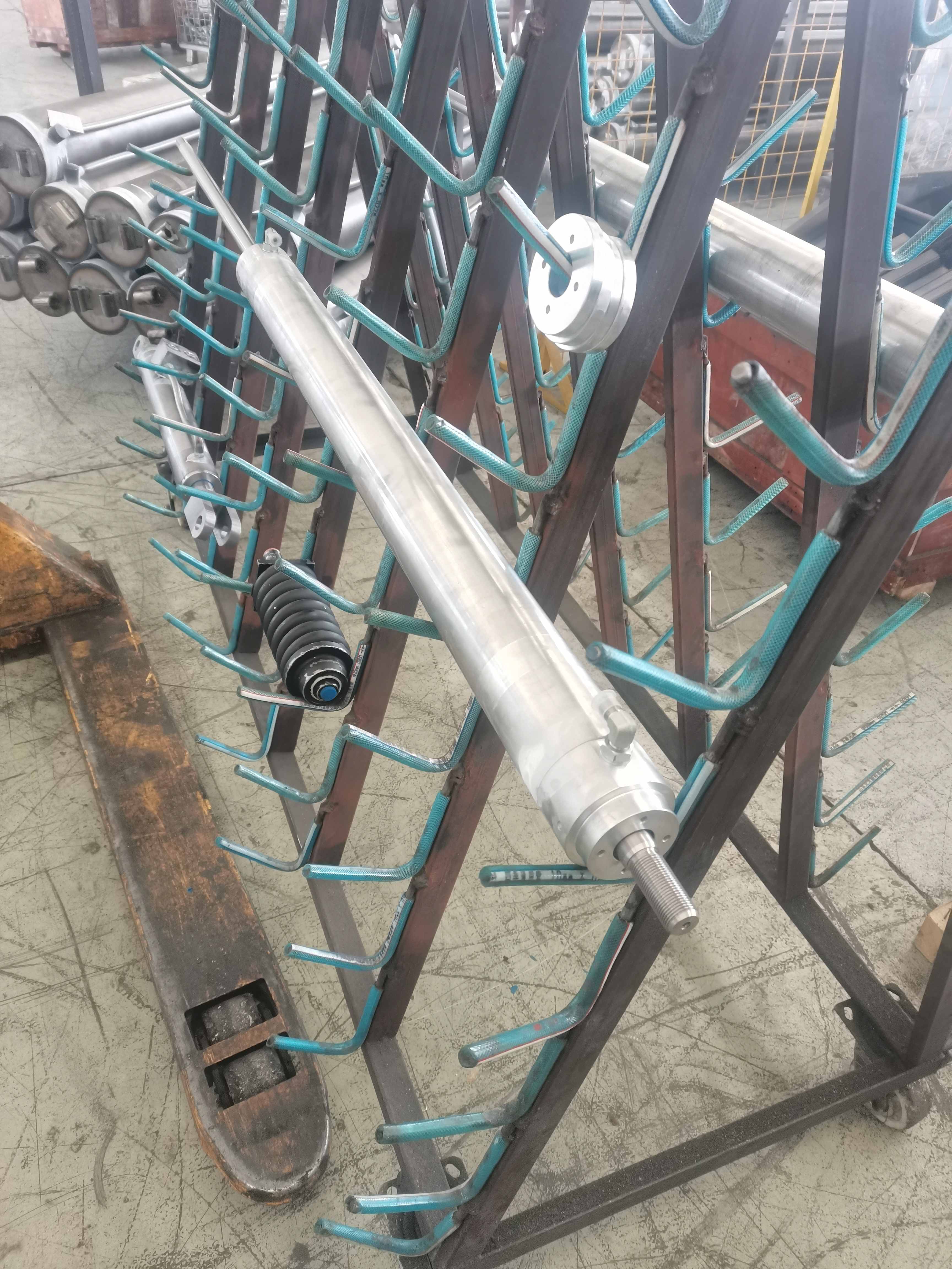
Custom Double-Rod / Through-Rod Hydraulic Cylinder
الموديل: APEX-CDRC Series
المعلمات: Cylinder Structure: Welded, tie-rod, threaded-head or flanged construction
Acting Type: Double Acting
Rod Configuration: Double Rod / Through Rod
Bore Diameter: 32–250 mm
Piston Rod Diameter: 16–160 mm
Stroke Length: 25–3,000 mm
Working Pressure: 100–250 bar
Maximum Design Pressure: Up to 350 bar for specially engineered configurations
Operating Temperature: -20°C to +80°C
Extended Temperature Range: -40°C to +120°C with application-specific seals and materials
Operating Speed: 5–500 mm/s
Hydraulic Medium: Mineral-based hydraulic oil or approved compatible fluid
Effective Area: Equal on both sides when both rod diameters are identical
Push Force: Equal in both movement directions when both rod diameters are identical
Pull Force: Equal in both movement directions when both rod diameters are identical
Extension Speed: Equal to retraction speed at the same hydraulic flow when both rod diameters are identical
Displacement Volume: Equal in both movement directions when both rod diameters are identical
Rod Diameter Difference: Optional unequal double-rod configuration for application-specific force or speed requirements
Stroke Symmetry: Centered or offset stroke configuration available
Retracted Length: Customized according to stroke, mounting style and equipment envelope
Overall Length: Determined by stroke, rod extensions and mounting arrangement
Rod Extension Length: Customized independently on both ends
Rod-End Style: Male thread, female thread, clevis, pin-eye, spherical bearing or custom-machined interface
Mounting Style: Center trunnion, foot mount, flange, side lug, tie-rod extension or custom mounting
Center Trunnion Position: Fixed or customized according to equipment geometry
Hydraulic Ports: SAE ORB, NPT, BSPP, metric thread, SAE flange or customer-specified connection
Port Position: Customized according to piping and equipment clearance
Port Size: Selected according to operating speed and hydraulic flow
End-of-Stroke Cushioning: Optional head-end, cap-end or dual-end cushioning
Flow-Control Integration: Optional flow-control valves for speed adjustment
Load-Holding Protection: Optional pilot-operated check valves or counterbalance valves
Mechanical Stroke Adjustment: Optional external stop or adjustable rod-end arrangement
Position Sensing: Optional proximity switches, magnetic sensors or continuous linear position transducer
Anti-Rotation: Optional keyed rod, guided rod or external guide system
Rod Protection: Optional bellows, protective sleeves or heavy-duty wipers on both rod ends
Surface Protection: Industrial paint, powder coating or corrosion-resistant treatment
Identification: Customer part number, serial number, logo and traceability code available
Testing: Dimensional inspection, pressure testing, leakage testing, speed comparison and full-stroke functional testing
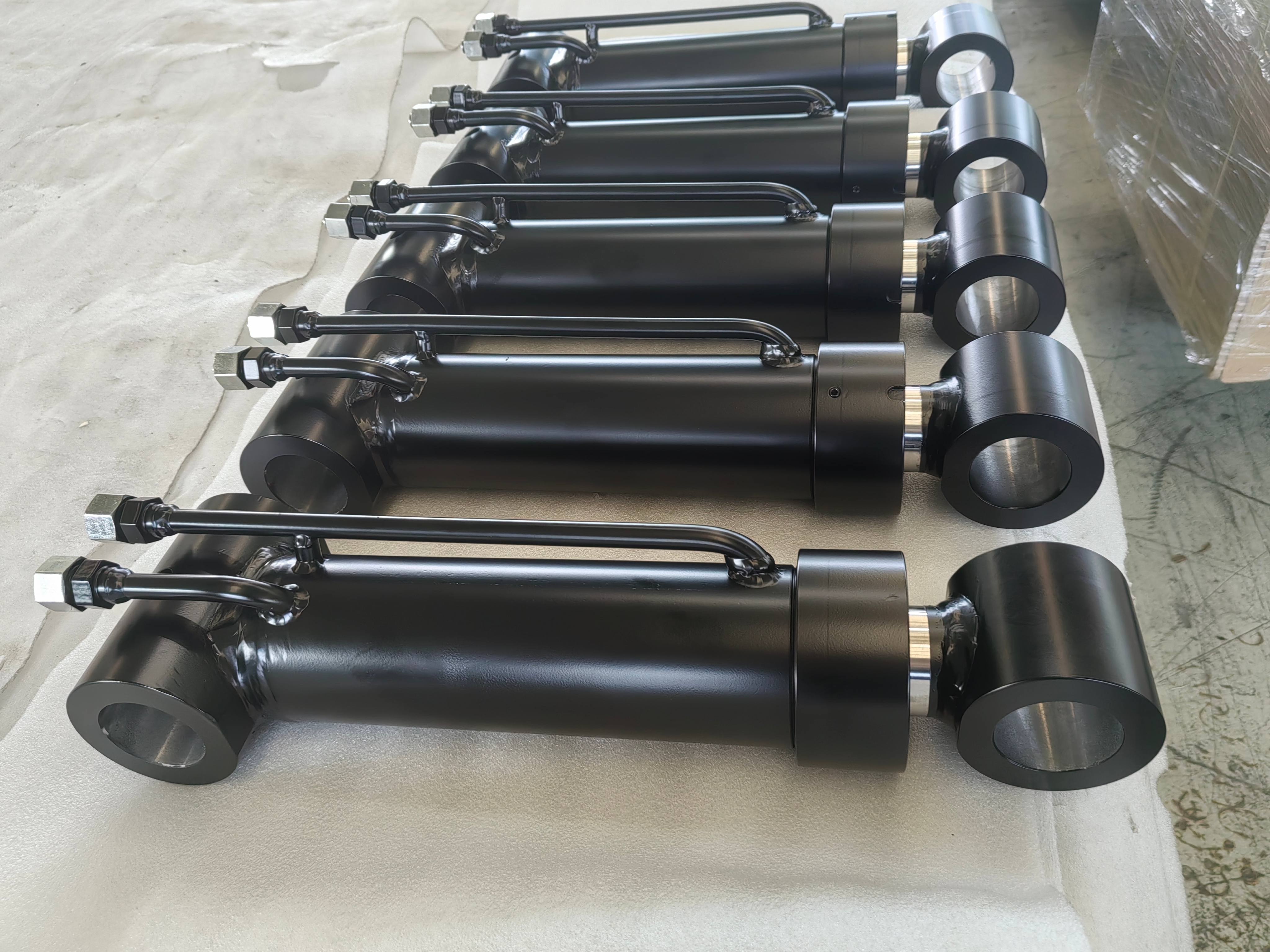
Custom Hydraulic Grapple & Attachment Cylinder
الموديل: APEX-CGAC Series
المعلمات: Cylinder Structure: Heavy-duty welded construction
Acting Type: Double Acting
Bore Diameter: 50–250 mm
Piston Rod Diameter: 30–180 mm
Stroke Length: 100–1,500 mm
Working Pressure: 160–350 bar
Maximum Design Pressure: Up to 420 bar for specially engineered configurations
Operating Temperature: -30°C to +100°C
Operating Speed: 10–500 mm/s
Hydraulic Medium: Mineral-based hydraulic oil or approved compatible fluid
Rated Push Force: Calculated according to bore diameter and working pressure
Rated Pull Force: Calculated according to annular piston area and working pressure
Peak Load: Determined according to gripping impact, equipment inertia and attachment geometry
Duty Cycle: Intermittent, repeated-duty or continuous material-handling operation
Load Direction: Alternating push-and-pull load
Shock-Load Capability: Engineered according to attachment type and operating conditions
Side-Load Resistance: Optimized through mounting geometry, guide length and bearing selection
Retracted Length: Customized according to grapple linkage and installation space
Extended Length: Retracted length plus effective stroke
Mounting Style: Pin-eye, clevis, cross-tube, spherical bearing or custom attachment mounting
Rod-End Style: Pin-eye, clevis, spherical bearing or custom machined connection
Base-End Style: Pin-eye, cross-tube, clevis or spherical bearing
Mounting-Pin Diameter: 30–180 mm
Bearing Type: Hardened steel bushing, bronze bushing, composite bushing or spherical plain bearing
Hydraulic Ports: SAE ORB, BSPP, metric thread, SAE flange or customer-specified connection
Port Position: Customized according to hose routing through the attachment movement
Port Protection: Recessed, guarded or reinforced port arrangement available
End-of-Stroke Cushioning: Optional single-end or dual-end cushioning
Load-Holding Valve: Optional pilot-operated check valve or counterbalance valve
Hose-Burst Protection: Optional integrated hose-burst valve
Regenerative Circuit Compatibility: Available according to speed and force requirements
Position Sensing: Optional proximity switch or integrated linear position sensor
Rod Protection: Optional protective sleeve, bellows or heavy-duty scraper system
Grease Fittings: Available on pin-eye and bushing mountings
Surface Protection: Industrial paint, powder coating, zinc-based coating or corrosion-resistant treatment
Color: Customized according to equipment or customer-brand requirements
Identification: Customer part number, serial number, logo and traceability marking available
Testing: Dimensional inspection, pressure testing, leakage testing and full-stroke functional testing
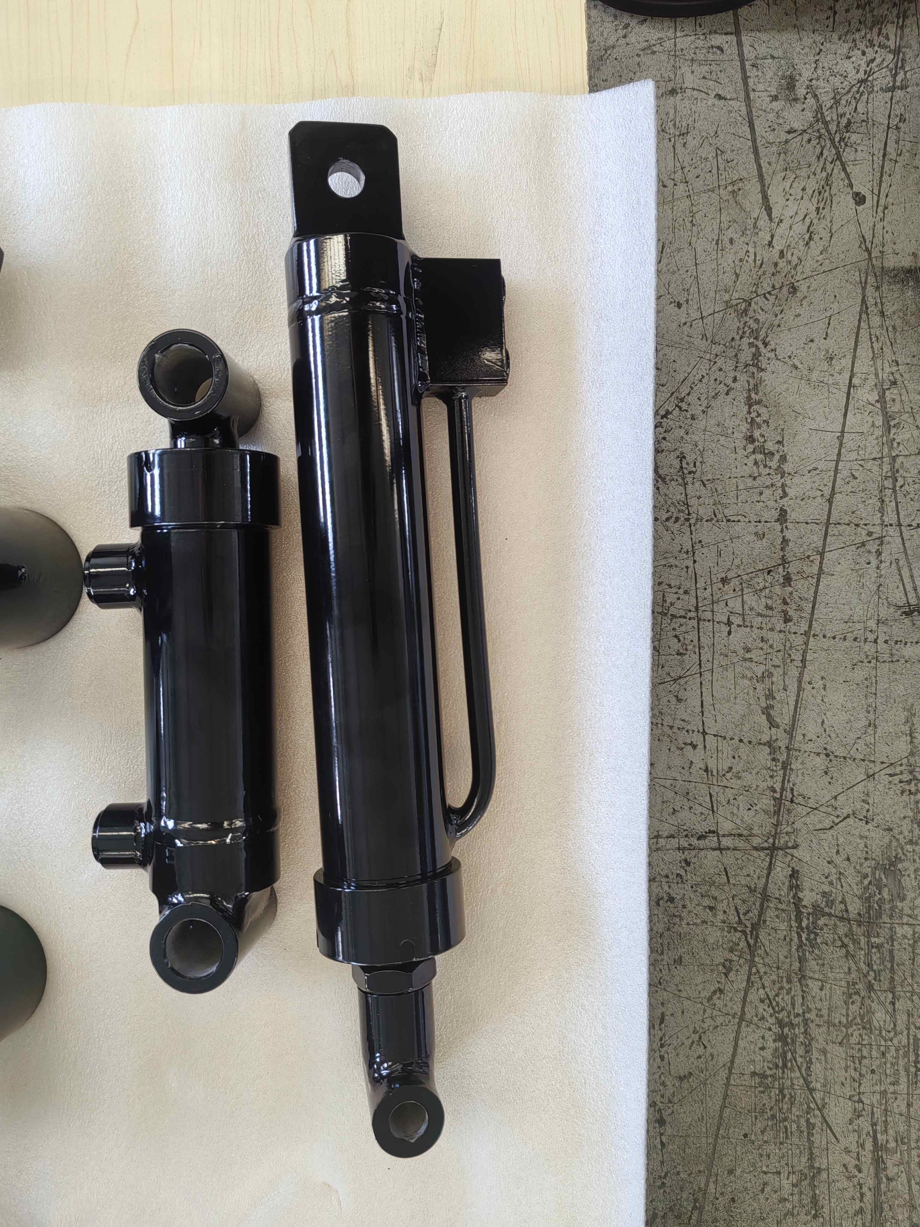
Custom Compact Short-Stroke High-Force Hydraulic Cylinder
الموديل: APEX-CCSC Series
المعلمات: Cylinder Structure: Compact welded, threaded or bolted construction
Acting Type: Single Acting or Double Acting
Bore Diameter: 40–250 mm
Piston Rod Diameter: 20–180 mm
Stroke Length: 10–500 mm
Working Pressure: 160–250 bar
Maximum Design Pressure: Up to 350 bar for specially engineered configurations
Operating Temperature: -20°C to +80°C
Extended Temperature Range: -40°C to +120°C with application-specific seals and materials
Hydraulic Medium: Mineral-based hydraulic oil or approved compatible fluid
Rated Push Force: Calculated according to bore diameter and working pressure
Rated Pull Force: Calculated according to annular piston area and working pressure
Operating Speed: 5–300 mm/s
Duty Cycle: Intermittent, repeated-duty or application-specific operation
Installation Direction: Horizontal, vertical, inclined or inverted
Retracted Length: Minimized according to stroke, mounting and internal construction
Extended Length: Retracted length plus effective stroke
Body Configuration: Round body, square body, block type or custom-machined body
Mounting Style: Front flange, rear flange, foot mount, clevis, trunnion, threaded body or custom mounting
Rod-End Style: Male thread, female thread, flat push plate, clevis, pin-eye or custom tool interface
Base-End Style: Flange, threaded base, foot mount, clevis or custom mounting
Hydraulic Ports: SAE ORB, NPT, BSPP, metric thread, cartridge cavity or customer-specified connection
Port Position: Side, rear, radial or customer-specified orientation
Port Size: Selected according to hydraulic flow and operating speed
End-of-Stroke Cushioning: Optional for higher-speed applications
Load-Holding Valve: Optional pilot-operated check valve or integrated valve block
Pressure Relief Protection: Optional integrated or external pressure-relief arrangement
Mechanical Locking: Optional threaded lock nut, locking collar or mechanical support arrangement
Return Method: Hydraulic power return, spring return or external load return
Position Sensing: Optional proximity sensor, magnetic sensor or short-range linear position sensor
Anti-Rotation Device: Optional guided rod, keyed piston rod or external guide arrangement
Surface Protection: Industrial paint, powder coating, zinc coating or application-specific treatment
Identification: Customer part number, serial number, logo and traceability code available
Testing: Dimensional inspection, pressure testing, leakage testing and full-stroke functional testing
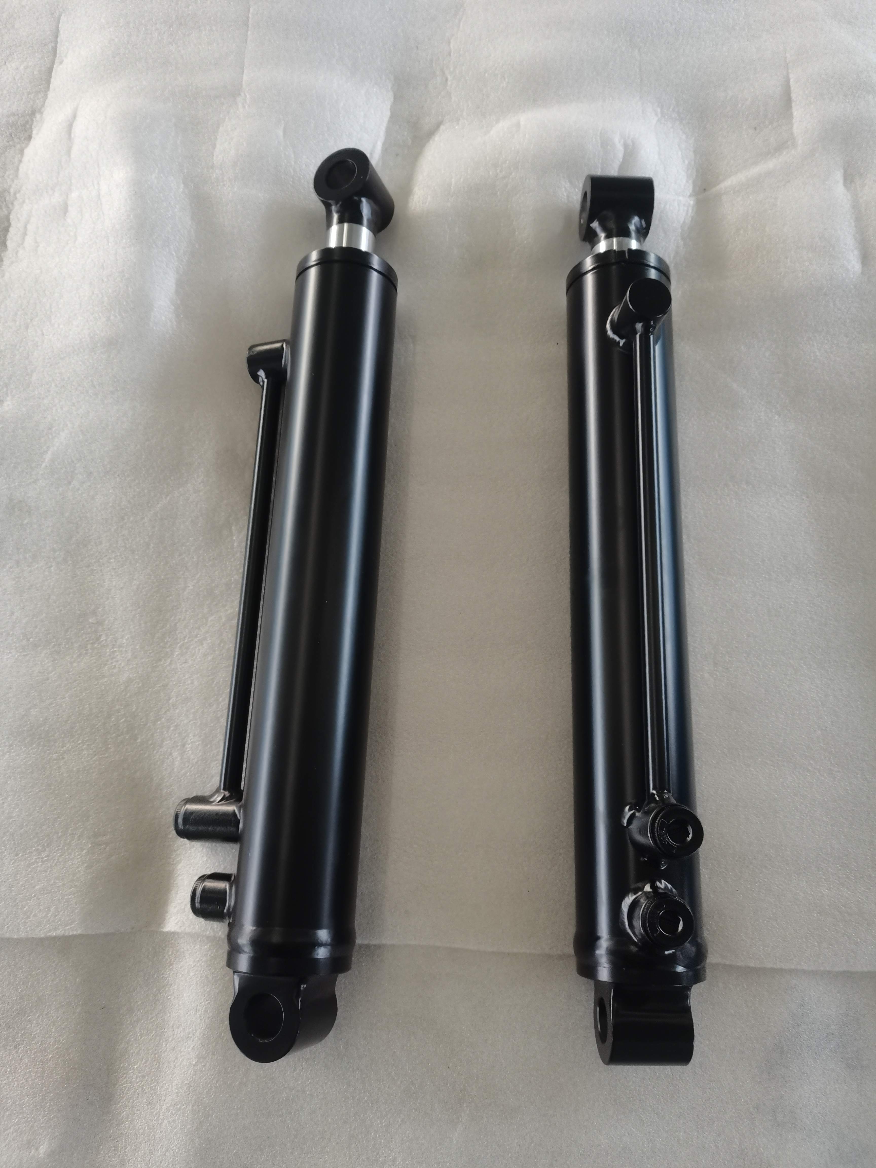
Custom Mill-Duty Hydraulic Cylinder
الموديل: APEX-CMDC Series
المعلمات: Bore Range: 50–320 mm, subject to Apex manufacturing confirmation
Rod Diameter Range: 28–220 mm, subject to engineering calculation and Apex manufacturing confirmation
Stroke Range: 50–3,000 mm; longer strokes require individual engineering review
Working Pressure: Up to 250 bar for the normal product range
Cylinder Structure: Heavy-duty roundline, flanged or threaded-head construction
Acting Type: Double Acting
Rod Configuration: Single Rod or Double Rod
Bore Diameter: Final size calculated according to required force and working pressure
Piston Rod Diameter: Selected according to load, stroke, buckling, fatigue and bearing requirements
Stroke Length: Manufactured according to the approved equipment drawing
Retracted Length: Customized according to installation dimensions and mounting style
Extended Length: Determined by retracted length and effective stroke
Working Pressure: Final value determined by the approved hydraulic-system specification
Maximum System Pressure: Must be confirmed before engineering approval
Proof-Test Pressure: Defined in the approved inspection and testing plan
Rated Push Force: Calculated from piston area and specified working pressure
Rated Pull Force: Calculated from annular piston area and specified working pressure
Peak Load: Evaluated according to shock load, machine inertia and operating cycle
Duty Cycle: Designed for frequent, repeated or continuous industrial operation
Fatigue Requirement: Defined according to pressure cycles, load spectrum and required service life
Operating Speed: Selected according to hydraulic flow, seal type and cushion design
Hydraulic Medium: Mineral-based hydraulic oil, water-glycol fluid or approved application-specific medium
Operating Temperature: Determined by hydraulic fluid, seals, proximity to heat sources and ambient conditions
Hydraulic Ports: SAE flange, BSPP, metric thread, SAE ORB, NPT or customer-specified connection
Port Size: Selected according to required flow and acceptable pressure loss
Port Position: Customized according to equipment piping and maintenance access
Mounting Style: Front flange, rear flange, intermediate trunnion, head trunnion, cap trunnion, clevis, spherical bearing, foot mount or custom mounting
Rod-End Connection: Male thread, female thread, clevis, spherical bearing or custom machined connection
Replaceable Gland: Standard design objective for simplified maintenance
Piston-Rod Removal: Designed according to the approved service and maintenance arrangement
Stop Tube: Optional for long-stroke cylinders and applications with increased bearing loads
End-of-Stroke Cushioning: Optional adjustable or fixed cushioning at either or both ends
Load-Holding Protection: Optional counterbalance valve, pilot-operated check valve or integrated valve block
Position Monitoring: Optional proximity switches, linear position sensor or continuous position transducer
Rod Protection: Optional bellows, metal scraper, protective sleeve or rod boot
Water Cooling: Optional application-specific cooling arrangement for high-temperature environments
Surface Protection: Industrial coating selected according to indoor, outdoor, chemical or high-temperature exposure
Identification: Customer part number, serial number and permanent traceability marking available
Testing: Dimensional inspection, pressure testing, leakage testing, cushioning verification and full-stroke cycling
Documentation: Approved drawing, material records, welding records, inspection report and pressure-test report available
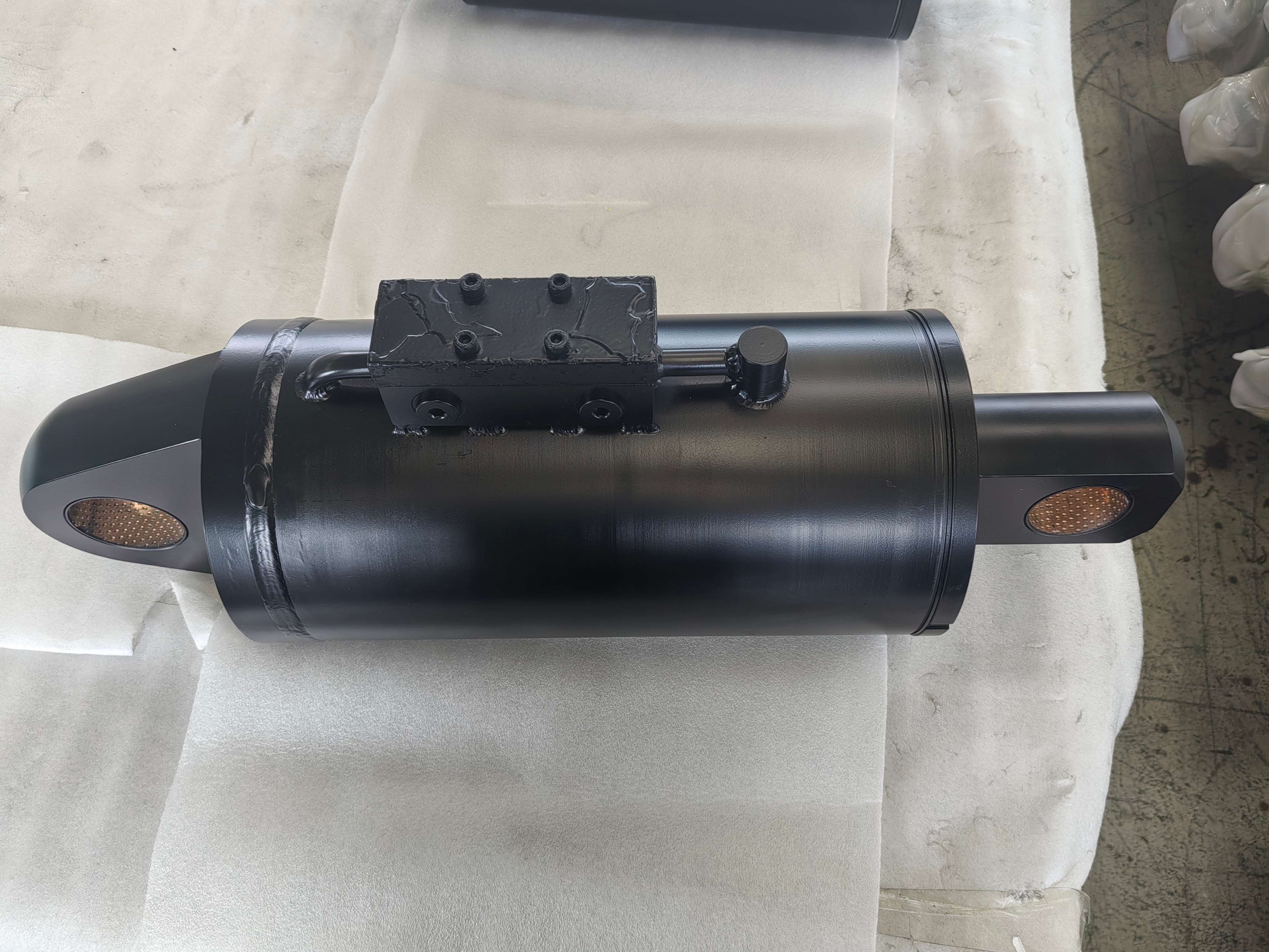
Custom Position-Sensing Hydraulic Cylinder
الموديل: APEX-CPSC Series
المعلمات: Bore Diameter Range: 40–320 mm
Rod Diameter Range: 25–220 mm
Stroke Range: 50–2,400 mm as a normal position-sensing range
Working Pressure: Up to 250 bar for the normal range
Cylinder Structure: Welded, threaded-head, tie-rod or heavy-duty mill-type construction
Acting Type: Double Acting
Position Feedback Type: Continuous or discrete position feedback
Continuous Sensor Type: Magnetostrictive linear position transducer, linear displacement transducer or approved equivalent
Discrete Sensor Type: Proximity switch, inductive sensor, reed switch or end-of-stroke switch
Sensor Installation: Internally integrated, cap-end mounted, externally mounted or application-specific arrangement
Measured Stroke: Selected according to the cylinder’s effective working stroke
Position Output: Analog voltage, analog current, SSI, CANbus, PWM, start/stop or customer-specified industrial communication output
Position Resolution: Determined by the selected sensor and control requirements
Position Repeatability: Determined by the selected sensor, mounting and operating conditions
Absolute Position Feedback: Optional
Incremental Position Feedback: Optional
Power-Off Position Retention: Available with suitable absolute-position sensor technology
Connector Type: Industrial plug connector, sealed cable outlet or customer-specified interface
Ingress Protection: Determined by sensor, connector and cable configuration
Bore Diameter: Final size calculated from required force and working pressure
Piston Rod Diameter: Final size determined by load, stroke, buckling and sensor-integration requirements
Stroke Length: Final value manufactured according to the approved drawing
Retracted Length: Customized according to the sensor configuration and installation envelope
Extended Length: Determined by retracted length and effective stroke
Working Pressure: Final value determined by the equipment hydraulic system
Maximum System Pressure: Must be confirmed before engineering approval
Proof-Test Pressure: Defined in the approved inspection and testing plan
Rated Push Force: Calculated from piston area and specified working pressure
Rated Pull Force: Calculated from annular piston area and specified working pressure
Operating Speed: Selected according to hydraulic flow, sensor response and equipment control requirements
Duty Cycle: Intermittent, repeated-duty or continuous automated operation
Hydraulic Medium: Mineral-based hydraulic oil or approved compatible fluid
Recommended Operating Temperature: -20°C to +80°C for the initial public range, subject to seal and sensor selection
Extended Temperature Design: Available after engineering review using compatible seals, cables, connectors and sensors
Hydraulic Ports: SAE ORB, NPT, BSPP, metric thread, SAE flange or customer-specified connection
Mounting Style: Clevis, pin-eye, cross-tube, trunnion, flange, spherical bearing or custom mounting
End-of-Stroke Cushioning: Optional head-end, cap-end or dual-end cushioning
Load-Holding Protection: Optional counterbalance valve, pilot-operated check valve or hose-burst valve
Manual Sensor Calibration: Available depending on sensor type
Controller Compatibility: Must be confirmed from the customer’s PLC, ECU or motion controller
EMC Requirement: Confirm according to the target equipment and applicable electrical standard
Testing: Pressure, leakage, full-stroke, sensor-output and signal-repeatability testing
Documentation: Approved drawing, sensor datasheet, wiring diagram, inspection record and test report available
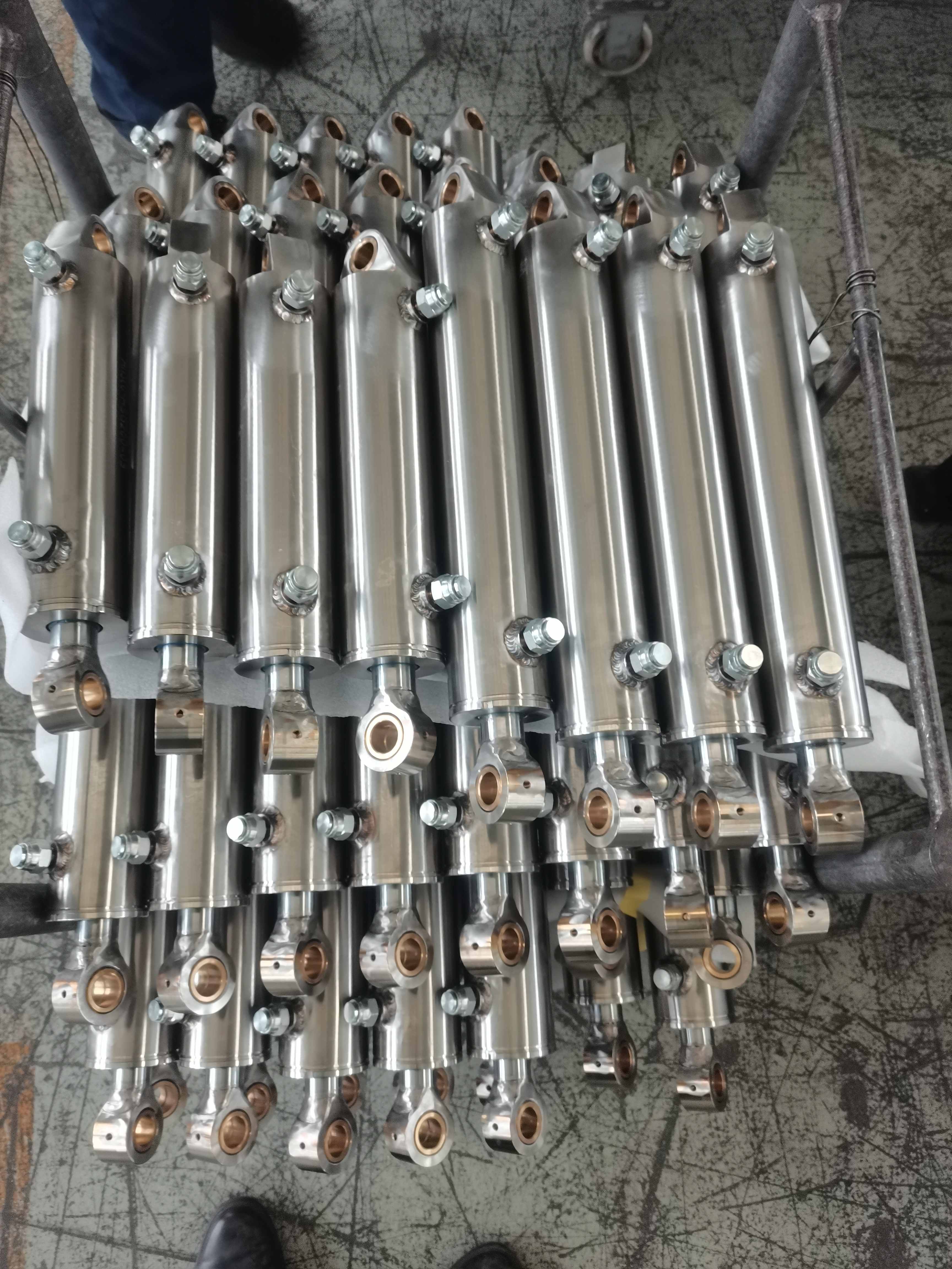
Custom Stainless Steel Corrosion-Resistant Hydraulic Cylinder
الموديل: APEX-CSSC Series
المعلمات: Cylinder Structure: Welded, threaded or application-specific corrosion-resistant construction
Acting Type: Single Acting or Double Acting
Bore Diameter: Customized according to required force and approved drawing
Piston Rod Diameter: Determined according to load, stroke, buckling and corrosion requirements
Stroke Length: Customized according to equipment movement
Retracted Length: Customized according to the available installation envelope
Extended Length: Determined by retracted length and effective stroke
Working Pressure: Customized according to the approved hydraulic-system specification
Maximum System Pressure: Must be confirmed before engineering approval
Proof-Test Pressure: Defined in the approved inspection and testing plan
Rated Push Force: Calculated from piston area and specified working pressure
Rated Pull Force: Calculated from annular piston area and specified working pressure
Operating Direction: Horizontal, vertical, inclined or changing-angle installation
Duty Cycle: Intermittent, repeated-duty or continuous-cycle operation according to application requirements
Corrosion Environment: Freshwater, saltwater, salt spray, high humidity, washdown or chemical exposure
Chemical Compatibility: Must be confirmed from the actual cleaning agents, process chemicals and hydraulic fluid
Hydraulic Medium: Mineral oil, biodegradable hydraulic fluid, water-glycol fluid or approved application-specific medium
Operating Temperature: Determined by the selected materials, sealing system and hydraulic fluid
Hydraulic Ports: SAE ORB, NPT, BSPP, BSPT, metric thread, sanitary-compatible interface or customer-specified connection
Port Material: Stainless steel or application-specific corrosion-resistant material
Port Position: Customized according to hose routing and washdown requirements
Mounting Style: Clevis, pin-eye, cross-tube, trunnion, flange, spherical bearing or custom mounting
Mounting Hardware: Stainless steel or corrosion-protected high-strength steel according to load requirements
Surface Finish: Polished, passivated, electropolished, coated or application-specific finish
Weld Treatment: Weld cleaning, pickling and passivation available according to project requirements
Drainage Design: Optional geometry to minimize water and cleaning-fluid retention
Protective Boots: Optional rod bellows or protective covers for aggressive environments
End-of-Stroke Cushioning: Optional single-end or dual-end cushioning
Load-Holding Protection: Optional counterbalance valve, pilot-operated check valve or hose-burst valve
Position Monitoring: Optional corrosion-resistant position sensor or stroke switch
Identification: Stainless-steel nameplate, engraved part number, serial number and traceability code available
Testing: Dimensional inspection, pressure testing, leakage testing and full-stroke functional testing
Additional Testing: Optional salt-spray, coating-thickness or material-verification documentation according to project requirements
Documentation: Approved drawing, inspection report, material records and pressure-test report available
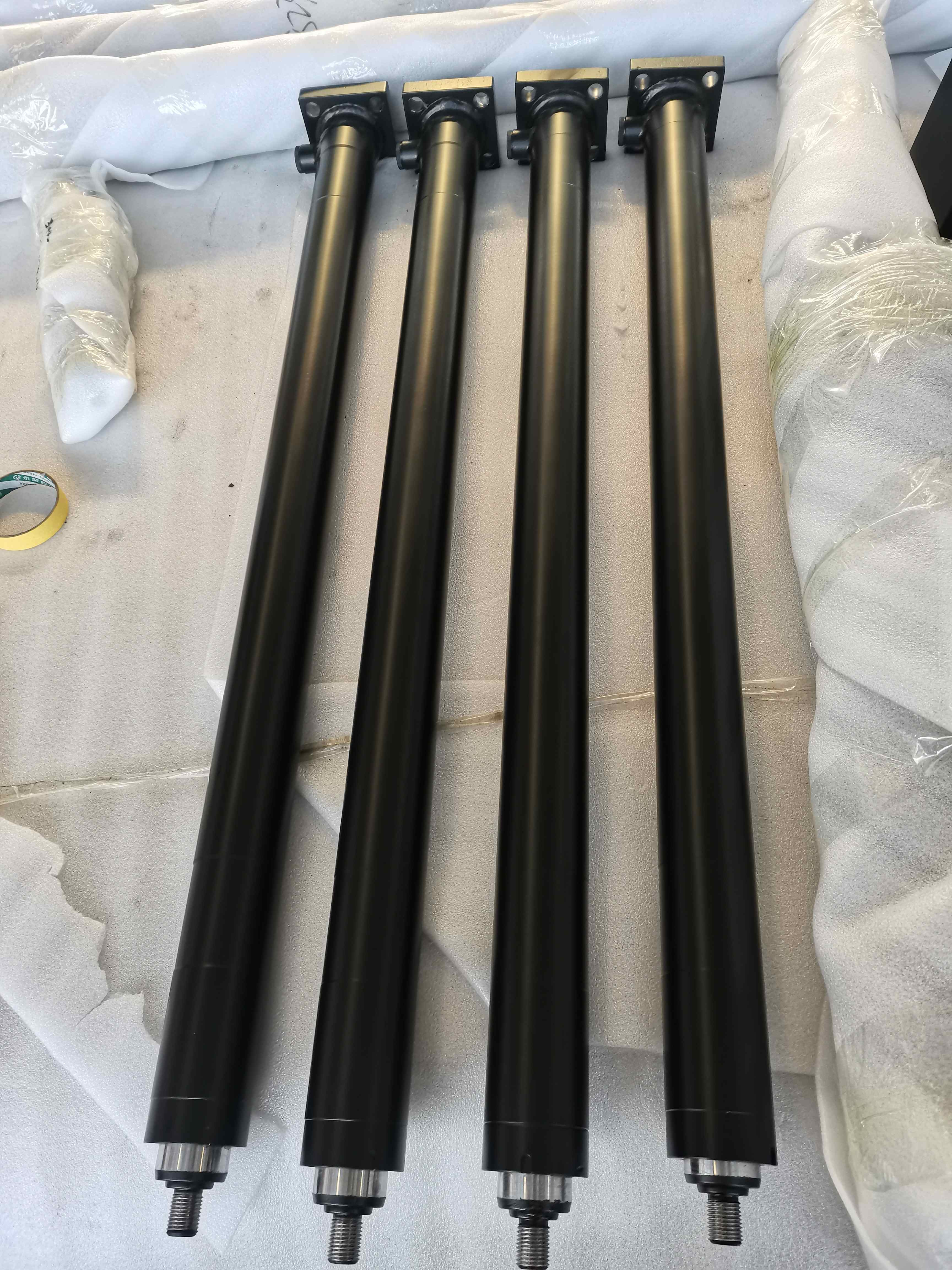
Custom Telescopic Hydraulic Cylinder
الموديل: APEX-CTC Series
المعلمات: Cylinder Structure: Multi-stage telescopic construction
Acting Type: Single Acting or Double Acting
Number of Stages: Customized according to required stroke and available retracted length
Largest Stage Diameter: Engineered according to required initial lifting force and working pressure
Intermediate Stage Diameters: Progressively sized according to load curve and structural requirements
Final Stage Diameter: Determined according to final-stage load, stability and mounting requirements
Total Stroke: Customized according to the required equipment movement
Stage Stroke Distribution: Engineered according to total stroke, overlap and stability requirements
Retracted Length: Minimized according to the number of stages and installation envelope
Extended Length: Determined by retracted length and total effective stroke
Stroke-to-Retracted-Length Ratio: Optimized according to the equipment installation space
Working Pressure: Customized according to the approved hydraulic-system specification
Maximum System Pressure: Must be confirmed before final engineering approval
Proof-Test Pressure: Defined in the approved inspection and testing plan
Initial Lifting Force: Calculated from the effective area of the largest stage and working pressure
Stage Output Force: Calculated separately for each telescopic stage
Load Curve: Must be evaluated throughout the complete tipping, lifting or ejecting cycle
Operating Direction: Vertical, inclined or application-specific installation
Return Method: Gravity return, external load return or hydraulic power return
Extension Sequence: Largest stage to smallest stage unless otherwise specified by the approved design
Retraction Sequence: Smallest stage to largest stage unless otherwise specified by the approved design
Stage Overlap: Engineered to maintain structural stability and guide support
Side-Load Condition: Telescopic cylinders must be protected from excessive side loading
Maximum Dump or Lift Angle: Determined by equipment geometry rather than by cylinder stroke alone
Operating Speed: Selected according to stage displacement, oil flow and stability requirements
Hydraulic Flow Requirement: Calculated according to cylinder displacement and required cycle time
Hydraulic Medium: Mineral-based hydraulic oil or approved compatible fluid
Operating Temperature: Determined by the selected seals, hydraulic fluid and operating environment
Hydraulic Port: SAE ORB, NPT, BSPP, metric thread, flange or customer-specified connection
Port Position: Customized according to hose routing and mounting orientation
Base Mounting: Trunnion, cross-tube, ball, clevis, flange or custom mounting
Rod-End Mounting: Ball, pin-eye, clevis, spherical bearing or custom mounting
Trunnion Position: Customized according to equipment geometry and tipping-force analysis
Bleed Port: Optional according to installation orientation and hydraulic-circuit requirements
Load-Holding Protection: Optional counterbalance valve, pilot-operated check valve or hose-burst valve
External Limit Device: Optional stroke limiter, safety cable or mechanical stop provision
Position Monitoring: Optional external stroke sensor or application-specific position-monitoring system
Surface Protection: Industrial paint or corrosion-resistant coating selected for the operating environment
Identification: Customer part number, serial number, logo and traceability code available
Testing: Dimensional inspection, pressure testing, leakage testing, stage-sequence testing and full-stroke cycling
Documentation: Approved drawing, dimensional report, test report and inspection records available
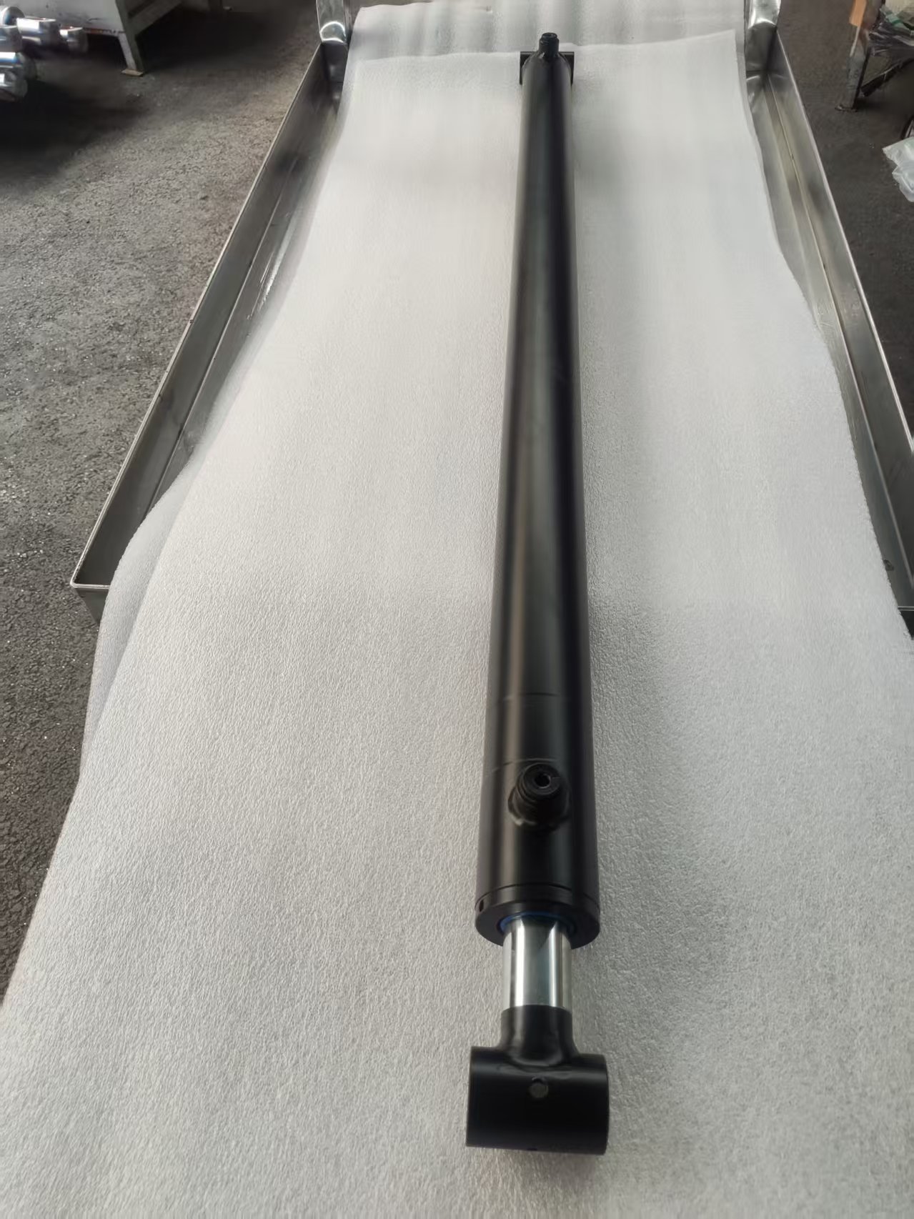
Custom Long-Stroke Hydraulic Cylinder
الموديل: APEX-CLSC Series
المعلمات: Cylinder Structure: Welded-body or application-specific long-stroke construction
Acting Type: Single Acting or Double Acting
Bore Diameter: Engineered according to required output force, operating pressure and installation envelope
Piston Rod Diameter: Determined through load, unsupported length, buckling and deflection calculations
Stroke Length: Customized according to the required equipment movement
Retracted Length: Minimized within the limits of the selected structure and mounting configuration
Extended Length: Determined by the retracted length and effective stroke
Pin-to-Pin Dimensions: Manufactured according to the approved installation drawing
Working Pressure: Customized according to the equipment hydraulic system
Maximum System Pressure: Must be confirmed before final engineering approval
Proof-Test Pressure: Defined in the approved inspection and testing plan
Rated Push Force: Calculated from effective piston area and specified working pressure
Rated Pull Force: Calculated from annular piston area and specified working pressure
Operating Direction: Horizontal, vertical, inclined or changing-angle installation
Load Direction: Compression, tension or alternating push-and-pull load
Rod Buckling Verification: Required for long-stroke compression applications
Rod Deflection Verification: Required for horizontal and inclined installations
Cylinder Alignment: Equipment mounting points must maintain acceptable coaxial alignment
Permissible Side Load: Defined according to the approved engineering calculation
Operating Speed: Selected according to bore size, hydraulic flow and stroke length
Flow Requirement: Calculated according to displacement volume and target cycle time
Duty Cycle: Intermittent, repeated-duty or application-specific operation
Hydraulic Medium: Mineral-based hydraulic oil or approved compatible fluid
Operating Temperature: Determined by the selected sealing system and hydraulic fluid
Hydraulic Ports: SAE ORB, NPT, BSPP, BSPT, metric thread, SAE flange or customer-specified connection
Port Size: Selected according to required flow and acceptable pressure loss
Port Position: Customized according to hose routing throughout the full movement
Mounting Style: Clevis, pin-eye, cross-tube, trunnion, flange, spherical bearing or custom mounting
Mounting Bearings: Replaceable bushings or spherical plain bearings available
End-of-Stroke Cushioning: Optional head-end, cap-end or dual-end hydraulic cushioning
Stroke Limitation: Optional internal stop, external stop or mechanical travel-control provision
Load-Holding Protection: Optional counterbalance valve, pilot-operated check valve or hose-burst valve
Position Monitoring: Optional linear position transducer, magnetostrictive sensor, proximity sensor or limit switch
Surface Protection: Industrial paint or application-specific corrosion-resistant coating
Identification: Customer part number, serial number, logo and traceability code available
Testing: Dimensional inspection, pressure testing, leakage testing and complete full-stroke cycling
Straightness Inspection: Barrel and piston-rod straightness inspected according to the approved drawing
Documentation: Approved drawing, dimensional report, pressure-test report and inspection records available
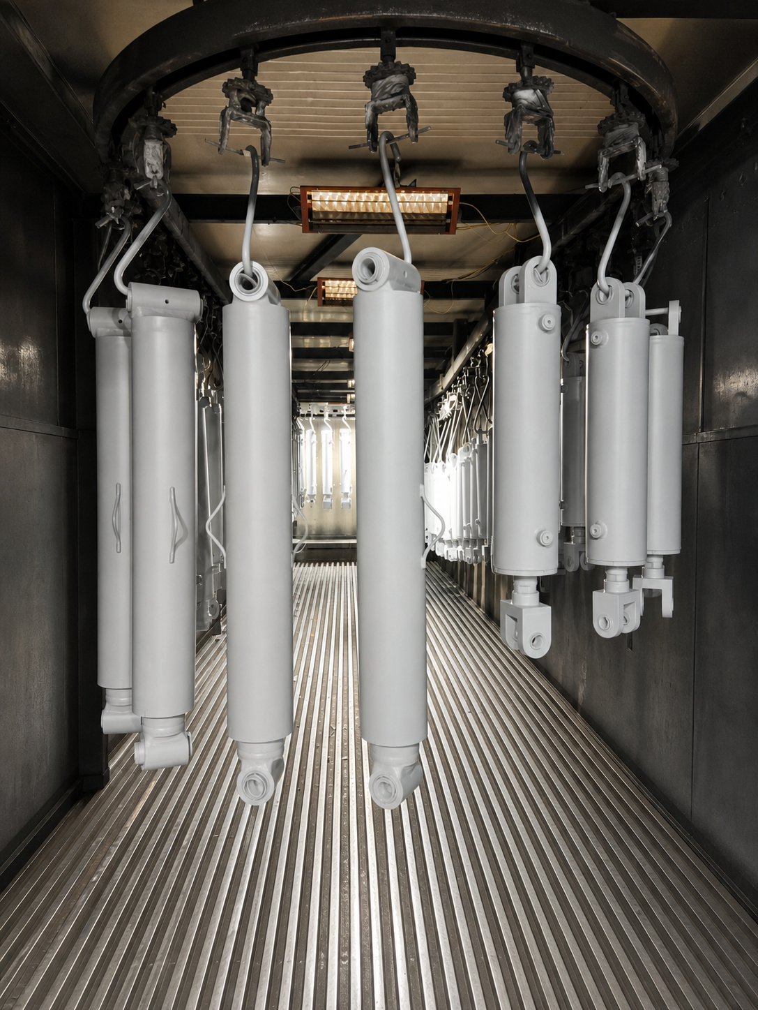
Custom Heavy-Duty High-Pressure Hydraulic Cylinder
الموديل: APEX-CHDC Series
المعلمات: Cylinder Structure: Heavy-duty welded-body or application-specific construction
Acting Type: Double Acting
Bore Diameter: Engineered according to required force, working pressure and installation envelope
Piston Rod Diameter: Determined by load direction, unsupported length, buckling calculation and side-load conditions
Stroke Length: Customized according to equipment movement and approved installation dimensions
Retracted Length: Customized according to the available mounting envelope
Extended Length: Determined by retracted length and effective stroke
Working Pressure: Customized according to the approved hydraulic-system specification
Maximum System Pressure: Must be confirmed before engineering approval
Proof-Test Pressure: Defined in the approved inspection and testing plan
Rated Push Force: Calculated from piston area and specified working pressure
Rated Pull Force: Calculated from annular piston area and specified working pressure
Peak Load: Evaluated according to equipment duty cycle and dynamic-load conditions
Load Direction: Compression, tension or alternating push-and-pull load
Duty Cycle: Intermittent, repeated-duty or continuous-cycle operation according to application requirements
Operating Speed: Engineered according to bore size, hydraulic flow and permissible piston velocity
Side-Load Condition: Must be evaluated during engineering review
Column Stability: Piston-rod buckling verification required for long-stroke compression applications
Hydraulic Medium: Mineral-based hydraulic oil or approved application-specific fluid
Operating Temperature: Determined by the selected sealing materials and hydraulic fluid
Hydraulic Ports: SAE ORB, NPT, BSPP, metric thread, SAE flange or customer-specified connection
Port Size: Selected according to required flow rate and acceptable pressure loss
Port Position: Customized according to hose routing and installation clearance
Mounting Style: Heavy-duty clevis, pin-eye, cross-tube, trunnion, flange, spherical bearing or custom mounting
Mounting-Pin Diameter: Calculated according to load and approved equipment interface
Bearing Type: Replaceable bushing, spherical plain bearing or hardened pin connection
End-of-Stroke Cushioning: Optional single-end or dual-end hydraulic cushioning
Load-Holding Protection: Optional counterbalance valve, pilot-operated check valve or hose-burst valve
Pressure Protection: Optional integrated relief valve or external circuit protection
Position Monitoring: Optional linear position transducer, magnetostrictive sensor, proximity sensor or stroke switch
Temperature Monitoring: Optional temperature sensor for critical-duty applications
Surface Protection: Industrial coating or application-specific anti-corrosion treatment
Identification: Part number, serial number, customer logo and traceability marking available
Testing: Dimensional inspection, pressure testing, leakage testing and full-stroke functional testing
Documentation: Approved drawing, inspection report, test report and material records available according to project requirements
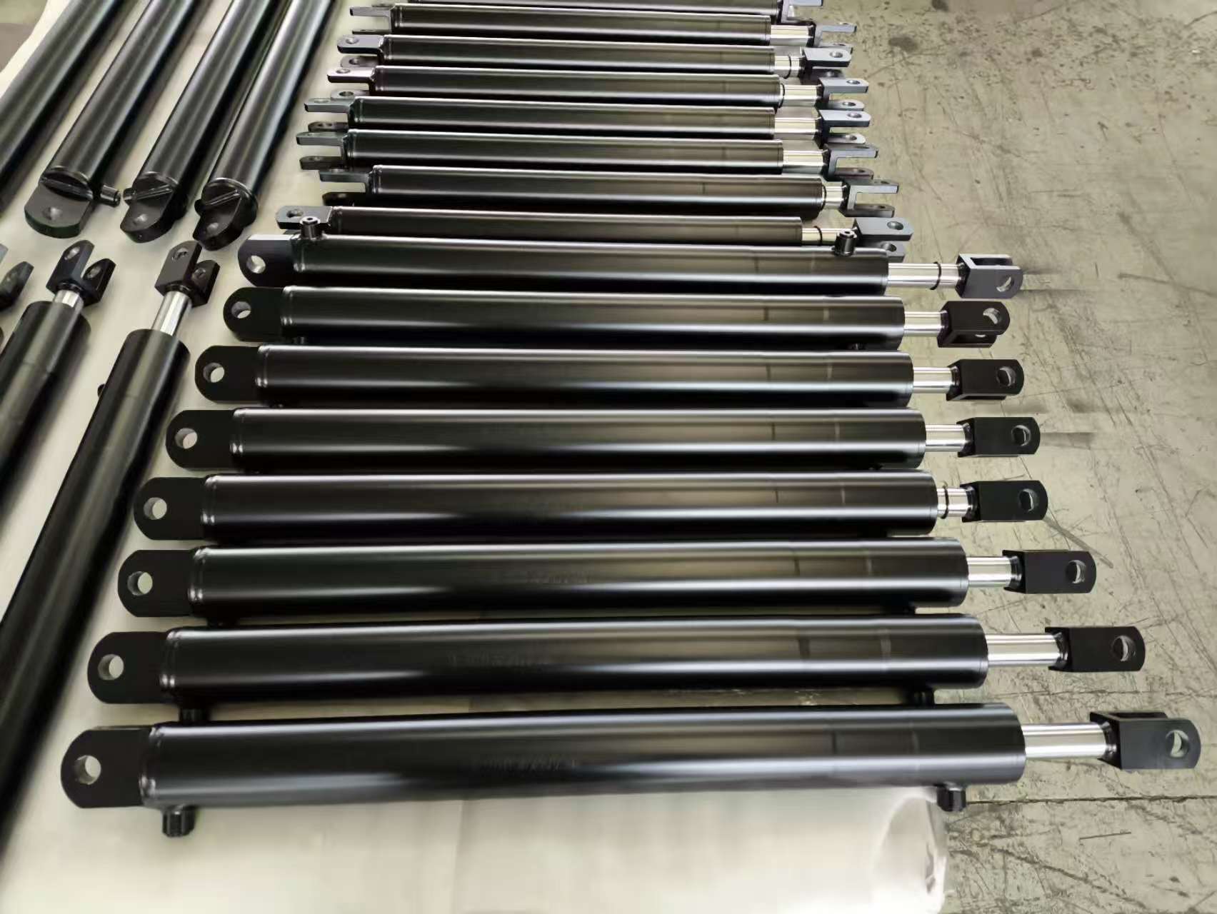
Custom Welded Double-Acting Hydraulic Cylinder
الموديل: APEX-CWDC Series
المعلمات: Cylinder Structure: Welded-body construction
Acting Type: Double Acting
Bore Diameter: Customized according to required output force and approved drawing
Piston Rod Diameter: Customized according to load, stroke, buckling calculation and approved drawing
Stroke Length: Customized according to equipment movement and installation envelope
Retracted Length: Customized according to equipment installation dimensions
Extended Length: Retracted length plus effective stroke, subject to approved drawing
Working Pressure: Customized according to the equipment hydraulic system
Proof-Test Pressure: Defined according to the approved technical specification and inspection plan
Rated Push Force: Calculated from effective piston area and specified working pressure
Rated Pull Force: Calculated from annular piston area and specified working pressure
Operating Speed: Defined according to hydraulic flow, bore size and application requirements
Hydraulic Medium: Mineral-based hydraulic oil or application-specific compatible fluid
Operating Temperature: Determined by the selected sealing system and hydraulic fluid
Hydraulic Ports: SAE ORB, NPT, BSPP, BSPT, metric thread, flange port or customer-specified connection
Port Position: Customized according to hose routing and installation requirements
Port Orientation: Axial, radial or customer-specified orientation
Cylinder Mounting: Cross-tube, clevis, pin-eye, trunnion, flange, foot mount, spherical bearing or customer-specific mounting
Rod-End Mounting: Clevis, pin-eye, threaded rod end, spherical bearing or custom machined connection
Base-End Mounting: Cross-tube, clevis, pin-eye, trunnion, flange or custom welded mounting
Cushioning: Optional head-end cushion, cap-end cushion or dual-end cushioning
Load-Holding Valve: Optional counterbalance valve, pilot-operated check valve or hose-burst valve
Position Sensing: Optional linear position sensor, proximity switch or external stroke sensor
Grease Fittings: Optional according to mounting and maintenance requirements
Surface Protection: Industrial paint, powder coating, zinc-based coating or application-specific corrosion protection
Color: Customized according to customer equipment or brand requirements
Identification: Customer logo, Apex label, serial number, part number or traceability code
Testing: Dimensional inspection, pressure testing, leakage testing and functional stroke testing
Documentation: Approved drawing, inspection record, test report and material documentation available according to project requirements
12K Hydraulic Trailer Jack Kit
الموديل: PJS-12-20-K
PJD-12-20-K
PJS-12-20-ADS-K
PJD-12-20-ADS-K
المعلمات: Rated Jack Capacity: 12,000 lb per trailer jack
Hydraulic Action: Double Acting
Nominal Travel: 20 in, as identified by the “20” designation in the published model numbers
Maximum Working Pressure: 3,200 PSI
Extend / Raising-Port Relief Setting: 3,200 PSI
Retract / Lowering-Port Relief Setting: 1,500 PSI
Maximum Hydraulic Flow Rate: 2 GPM
Hydraulic Port Type: 3/8 in BSPP
Power Supply: 12 VDC for kits equipped with a hydraulic power unit
Maximum Permitted Distance Between Ground and Bottom of Trailer Frame: 8 in
Single Complete Kit Configuration: One 12,000 lb trailer jack, double-acting hydraulic power unit and plumbing components
Tandem Complete Kit Configuration: Two 12,000 lb trailer jacks, double-acting hydraulic power unit, plumbing components and flow divider
Single Add-On Configuration: One 12,000 lb trailer jack, selector valve, hydraulic hoses and fittings
Tandem Add-On Configuration: Two 12,000 lb trailer jacks, selector valve, hydraulic hoses and fittings
PJS-12-20-K: Single-jack complete hydraulic kit with HPU
PJD-12-20-K: Tandem-jack complete hydraulic kit with HPU and flow divider
PJS-12-20-ADS-K: Single-jack add-on kit with selector valve
PJD-12-20-ADS-K: Tandem-jack add-on kit with selector valve
Power-Jack Mounting Plate Outside Dimensions: Approximately 5.53 in × 5.53 in, subject to verification against the approved installation drawing
Recommended Fitting Tightening Torque at Jack Ports: 12–14 ft-lb
Installation Type: Trailer-frame-mounted hydraulic landing leg
Roll-Off Hoist Hydraulic Cylinder
الموديل: Compatible replacement hydraulic cylinders manufactured according to verified roll-off hoist reference part numbers, equipment models and approved technical dimensions.
Verified SL-180 Reference Cylinders:
21P92 — Lift/Dump Hydraulic Cylinder
Cylinder Size: 5.25-inch bore x 54-inch stroke
21P91 — Jib Hydraulic Cylinder
Cylinder Size: 3-inch bore x 36-inch stroke
Verified SL-400 Reference Cylinders:
21P44 — Lift/Dump Hydraulic Cylinder
Cylinder Size: 6-inch bore x 60-inch stroke
21P45 —
المعلمات: Product Type: Heavy-duty welded hydraulic cylinder
Operating Type: Double acting
Primary Application: North American roll-off trucks
Compatible Hoist Type: Cable hoist
Compatible Hoist Type: Hooklift hoist
Compatible Hoist Type: Sliding-jib hooklift
Compatible Hoist Type: Articulating hooklift
Verified Reference Bore Range: 3–7 inches
Verified Reference Stroke Range: 17–74 inches
Verified Reference Rod Diameter: 1.5–2.5 inches where officially published
Cylinder Function: Lift / dump / winch / jib / tilt / locking / stabilizing
Mounting Style: Pin-eye or application-specific pivot mounting
Counterbalance Valve: Available for lift, dump, jib and tilt cylinders
Load-Holding Protection: Counterbalance valve configuration available
Cushioning: Available according to the approved original design
Hydraulic Ports: SAE O-ring or application-specific North American threads
Port Position: Reproduced according to the confirmed equipment configuration
Working Pressure: Matched to the roll-off hoist hydraulic system
Galbreath U5-OX System Pressure Reference: 1,850 PSI
Stellar Shuttle32 System Pressure Reference: 4,200 PSI
Working Pressure Statement: Pressure must be confirmed for each hoist model and cylinder function
Bore Diameter: Manufactured according to the verified part number or approved drawing
Rod Diameter: Manufactured according to the verified part number or approved drawing
Stroke Length: Manufactured according to the verified part number or approved drawing
Closed Length: Manufactured according to confirmed pin-to-pin dimensions
Extended Length: Determined by closed length and effective stroke
Mounting Pin Diameter: Reproduced according to the original installation
Mounting Width: Reproduced according to the original installation
Cylinder Orientation: Horizontal or inclined installation according to hoist design
Surface Finish: Heavy-duty industrial painted coating
Standard Color: Black
Optional Color: Customer-specified equipment color
Technical Confirmation: Approved production drawing required before manufacturing
Quality Inspection: Raw material inspection
Quality Inspection: Bore and rod dimensional inspection
Quality Inspection: Mounting-dimension inspection
Quality Inspection: Weld inspection
Quality Inspection: Hydraulic pressure testing
Quality Inspection: Internal leakage testing
Quality Inspection: External leakage testing
Quality Inspection: Full-stroke functional testing
Final Inspection: 100% inspection before shipment
Verified Standard Cylinder Range Summary
Lift/Dump Cylinder Bore Range: 4–7 inches
Lift/Dump Cylinder Stroke Range: 52.38–74 inches
Jib/Tilt Cylinder Bore Range: 3–5 inches
Jib/Tilt Cylinder Stroke Range: 17–52 inches
Published Rod Diameter Range: 1.5–2.5 inches
Maximum Verified Reference Stroke: 74 inches
Minimum Verified Reference Stroke: 17 inches
Note: The ranges above are calculated only from the verified SwapLoader, Stellar and Galbreath references listed in this product unit. They do not represent every roll-off hoist cylinder used in North America.
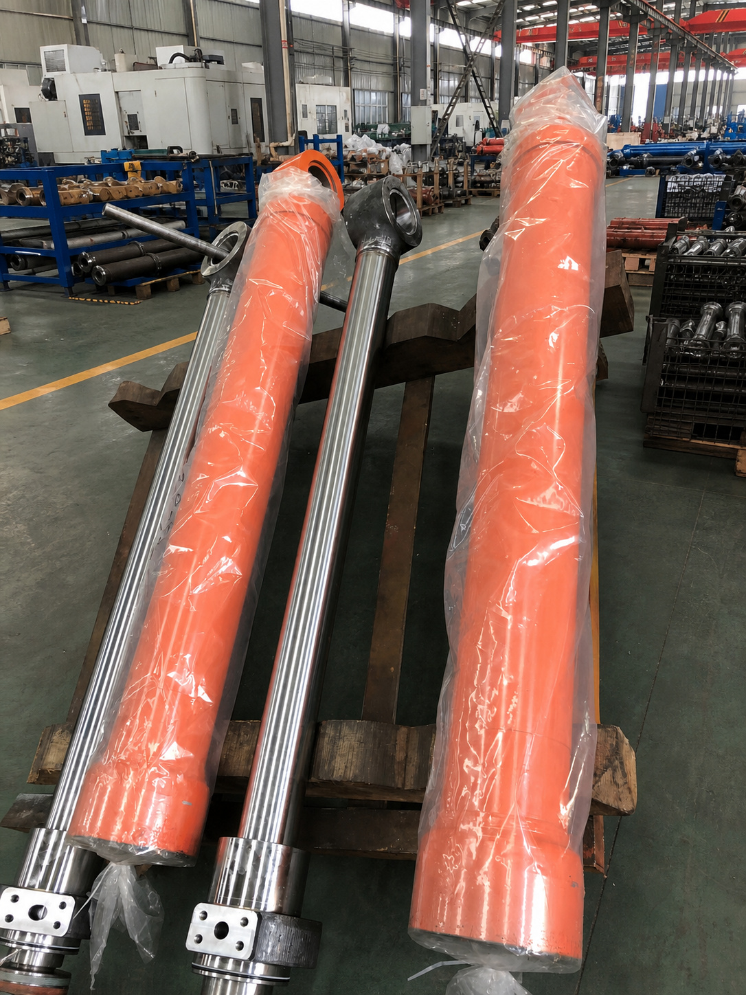
Replacement Hydraulic Cylinder for Komatsu Equipment
الموديل: Compatible replacement hydraulic cylinders manufactured according to verified Komatsu reference part numbers, equipment models and approved technical dimensions.
Verified Komatsu Boom Cylinder Reference Part Numbers:
707-F1-01380
707-01-0K751
99200040
99204040
99211040
99219940
99232040
92680070
77031773 — PC8000 Boom Cylinder Reference
Verified Komatsu Arm Cylinder Reference Part Numbers:
707-F1-00740
707-01-0K773
Verified Komatsu Bucket Cylinder Reference Part Numbers:
707-01-0C
المعلمات: Product Type: Build-to-print compatible replacement hydraulic cylinder
Product Identification: Komatsu reference part number
Machine Identification: Complete equipment model required
Serial Identification: Machine serial number required
Cylinder Position: Boom / arm / bucket / lift / tilt / steering / suspension / hoist / ripper
Acting Type: Single acting or double acting according to the original application
Bore Diameter: Manufactured according to the approved reference drawing or verified sample
Rod Diameter: Manufactured according to the approved reference drawing or verified sample
Stroke Length: Manufactured according to the approved reference drawing or verified sample
Closed Length: Manufactured according to the confirmed pin-to-pin dimension
Open Length: Manufactured according to the confirmed equipment requirement
Mounting Style: Eye / clevis / trunnion / flange or application-specific mounting
Pin Diameter: Matched to the verified installation dimensions
Mounting Width: Matched to the verified installation dimensions
Hydraulic Port Type: Matched to the original thread standard and port location
Cushioning Configuration: Confirmed according to the original cylinder design
Holding Valve Interface: Available where required by the original application
Working Pressure: Matched to the confirmed machine hydraulic system
Proof Pressure: Established through the approved technical specification
Seal Configuration: Selected according to pressure, temperature, oil type and working environment
Operating Temperature: Confirmed according to the application requirements
Surface Finish: Industrial painted finish
Standard Color: Komatsu-compatible yellow or customer-specified color
Technical Confirmation: Approved production drawing required before manufacturing
Quality Inspection: Incoming material inspection
Quality Inspection: Dimensional inspection
Quality Inspection: Weld inspection
Quality Inspection: Rod surface inspection
Quality Inspection: Hydraulic pressure testing
Quality Inspection: Internal and external leakage testing
Quality Inspection: Full-stroke functional testing
Final Inspection: 100% inspection before shipment
Officially Confirmed Komatsu Reman Application Families
Crawler Excavator Boom / Arm / Bucket Cylinders: PC800–PC2000
Rigid Dump Truck Hoist / Steering / Suspension Cylinders: HD465–HD1500
Large Wheel Loader Dump / Lift / Steering Cylinders: WA900–WA1200
Note: These equipment ranges describe Komatsu’s officially published Reman cylinder program. Availability of Apex-compatible replacements must be confirmed by part number and technical review.
Numerical Parameter Statement
Universal Bore Range: Not published as a single Komatsu standard range
Universal Rod Diameter Range: Not published as a single Komatsu standard range
Universal Stroke Range: Not published as a single Komatsu standard range
Universal Working Pressure Range: Not published as a single Komatsu standard range
Final Manufacturing Parameters: Determined individually from the verified part number, approved drawing or measured sample
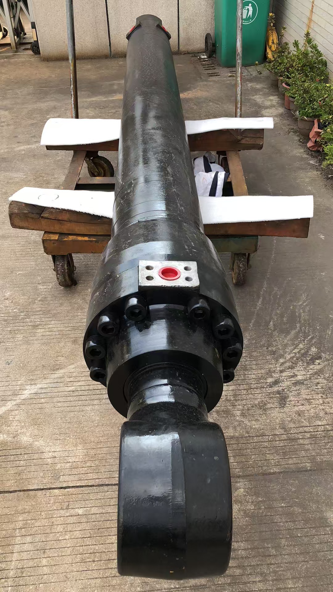
Replacement Hydraulic Cylinder for Caterpillar Equipment
الموديل: Compatible replacement cylinders manufactured according to confirmed Caterpillar reference part numbers, equipment models and approved technical dimensions.
Verified Caterpillar Reference Part Numbers:
509-6996 Cylinder Group
604-9013 Cylinder Group
495-5995 Cylinder Group
495-6000 Cylinder Group
532-9472 Cylinder Group
510-7951 Cylinder Group
190-3085 Cylinder Group
512-2357 Boom Cylinder Group / Cat Reman Reference 30R-1155
Additional Caterpillar replacement part numbers are availabl
المعلمات: Product Type: Build-to-print compatible replacement hydraulic cylinder
Product Identification: Caterpillar reference part number
Equipment Identification: Machine model and serial number required
Cylinder Function: Boom / arm / bucket / lift / tilt / steering / stabilizer / suspension / quick coupler
Acting Type: Single acting or double acting according to the original application
Bore Diameter: Manufactured according to the confirmed reference drawing or sample
Rod Diameter: Manufactured according to the confirmed reference drawing or sample
Stroke Length: Manufactured according to the confirmed reference drawing or sample
Closed Length: Manufactured according to the confirmed pin-to-pin dimension
Open Length: Determined by closed length and effective stroke
Mounting Dimensions: Reproduced according to the approved drawing or physical sample
Hydraulic Ports: Matched to the confirmed original thread type and position
Working Pressure: Matched to the equipment hydraulic system requirements
Seal Configuration: Selected according to pressure, temperature, oil type and duty cycle
Surface Finish: Industrial paint or customer-specified coating
Standard Color: Caterpillar-compatible yellow or customized color
Technical Confirmation: Drawing approval required before production
Quality Inspection: Dimensional inspection
Quality Inspection: Welding inspection
Quality Inspection: Hydraulic pressure testing
Quality Inspection: Leakage testing
Quality Inspection: Functional stroke testing
Final Inspection: 100% inspection before shipment
Verified CAT Reference Specification Range
The following range is calculated only from the CAT reference parts listed below and must not be interpreted as the complete Caterpillar cylinder range.
Verified Bore Diameter Range: 80–120 mm
Verified Rod Diameter Range: 45–65 mm
Verified Stroke Range: 525–1,531.9 mm
Verified Closed Length Range: 575–1,925.7 mm
Verified Working Pressure Range: 250–280 bar
Verified Port Types: UN / STOR / ORFS and model-specific hydraulic threads
Verified Reference Example 1
Reference Part Number: 509-6996
Application: Motor graders
Compatible Equipment: CAT 14 / 14M / 14M3 / 16 / 16M / 16M3 / 18 / 18M3
Closed Length: 1,925.7 mm
Stroke: 1,531.9 mm
Bore Diameter: 101.6 mm
Rod Diameter: 63.5 mm
Working Pressure: 275.6 bar
Port Thread: 3/4-16
Verified Reference Example 2
Reference Part Number: 604-9013
Application: Backhoe loader hydraulic system
Compatible Equipment: CAT 420E
Open Length: 2,321 mm
Closed Length: 1,378 mm
Stroke: 943 mm
Bore Diameter: 120 mm
Rod Diameter: 60 mm
Working Pressure: 250 bar
Port A: 1-3/16-12 UN male
Port B: 1-1/16-12 UN female
Verified Reference Example 3
Reference Part Number: 495-5995
Application: Wheel loader hydraulic system
Compatible Equipment: CAT 930 / 930K / 930M
Closed Length: 1,279.6 mm
Stroke: 728 mm
Bore Diameter: 120 mm
Rod Diameter: 65 mm
Working Pressure: 250 bar
Cap-End Port: 1-5/16-12 STOR
Rod-End Port: 1-7/16-12 ORFS
Verified Reference Example 4
Reference Part Number: 495-6000
Application: Wheel loader hydraulic system
Compatible Equipment: CAT 938 / 938K / 938M
Closed Length: 1,305.2 mm
Stroke: 788.6 mm
Bore Diameter: 120 mm
Rod Diameter: 65 mm
Working Pressure: 280 bar
Cap-End Port: 1-5/16-12 STOR
Rod-End Port: 1-7/16-12 ORFS
Verified Reference Example 5
Reference Part Number: 532-9472
Application: Motor grader hydraulic system
Compatible Equipment: CAT 120 GC / 140 GC
Closed Length: 575 mm
Stroke: 525 mm
Bore Diameter: 80 mm
Rod Diameter: 45 mm
Port Thread: 3/4-16
Verified Reference Example 6
Reference Part Number: 510-7951
Application: Backhoe loader hydraulic system
Compatible Equipment: CAT 415 / 415F2 / 416 / 416F2 / 420 / 420F2 / 420XE
Closed Length: 1,247 mm
Stroke: 852 mm
Bore Diameter: 90 mm
Rod Diameter: 60 mm
Working Pressure: 250 bar
Cap-End Port: 1-1/16 STOR
Rod-End Port: 1 ORFS
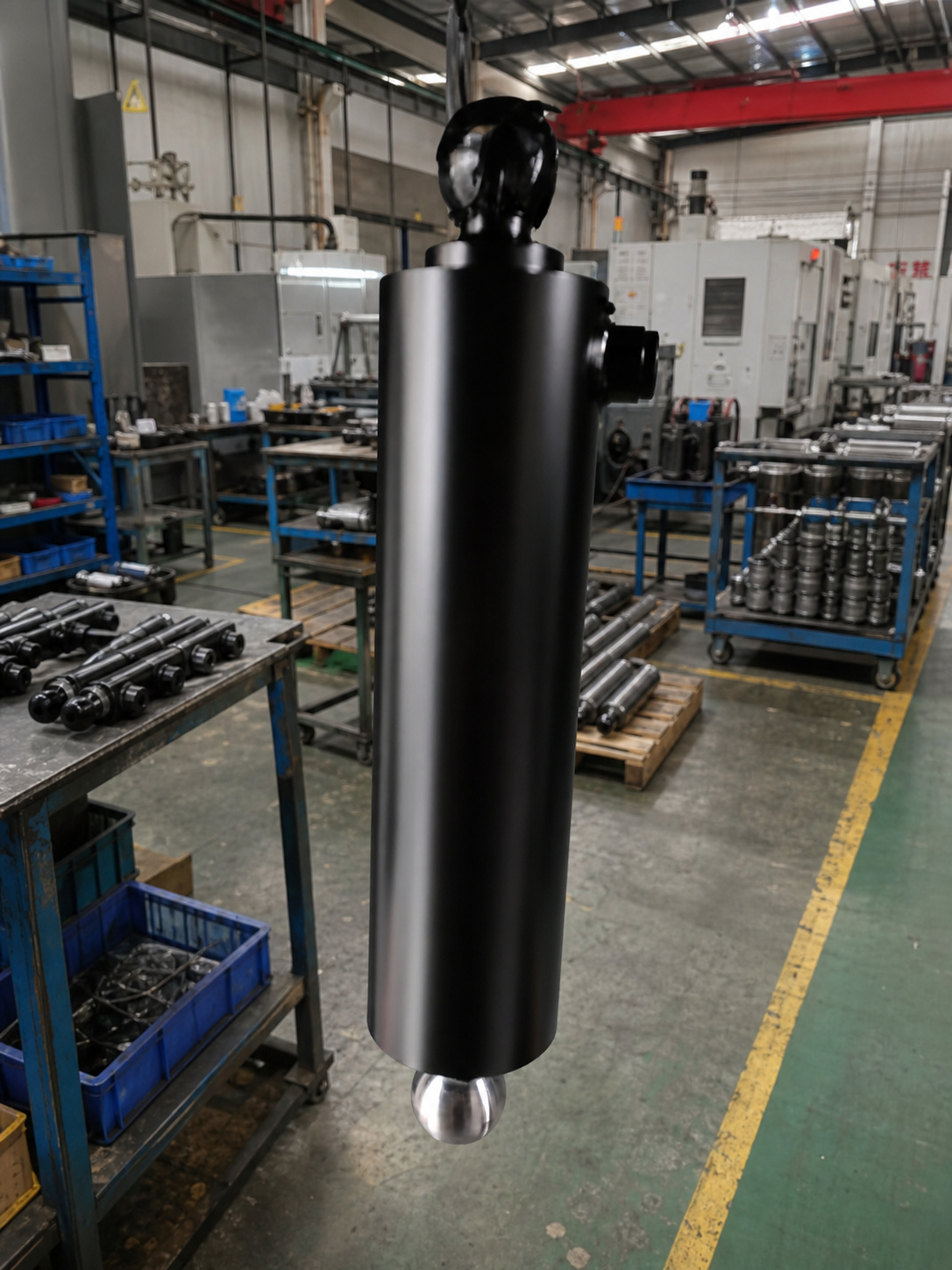
Underbody Telescopic Hydraulic Cylinder for Dump Trailers
الموديل: L120 Series:
6TG-E120x2057
5TG-E120x1710
4TG-E120x1369
6TG-E120x1727
5TG-E120x1435
4TG-E120x1145
6TG-E120x1241
5TG-E120x1030
4TG-E120x868
L105 Series:
5TG-E105x1872
4TG-E105x1492
5TG-E105x1432
4TG-E105x1140
3TG-E105x855
5TG-E105x1237
4TG-E105x984
5TG-E105x1050
4TG-E105x816
6TG-E105x1172
5TG-E105x1200
L90 Series:
3TG-E90x1199
4TG-E90x1140
3TG-E90x848
5TG-E90x1256
4TG-E90x1050
4TG-E90x984
4TG-E90x816
4TG-E90x676
L75 Series:
3TG-E75x1055
3TG-E75x910
3TG-E75x860
المعلمات: Product Series: L120 / L105 / L90 / L75
Number of Catalogue Models: 31 unique model codes
Number of Extension Stages: 3–6 stages
Power Stroke Range: 676–2,057 mm
Maximum Working Pressure: 200–220 bar
Tipping Capacity Range: 4–21 tons
Cylinder Mass Range: 19–51 kg
Working Oil Volume Range: 2.9–12.1 L
Closed Length L Range: 367–598 mm
Maximum Ball Articulation Angle: 30°
Operating Type: Single acting
Extension Method: Hydraulic power extension
Retraction Method: Gravity return during trailer-body lowering
Standard Installation Position: Under the dump trailer body
Main Mounting Type: Transverse pivot / trunnion mounting
Upper Connection: Induction-hardened ball connection
Optional Upper Connection: Rod eye with pin
Optional Lower Connection: Rod eye with lower pin
Hydraulic Port Options: G1/2
Hydraulic Port Options: G3/8
Hydraulic Port Options: M22
Hydraulic Port Options: M18
Hydraulic Port Options: NPT 1/2
Available Accessories: Cylinder support
Available Accessories: Cylinder cradle
Compatible System Components: Hydraulic power pack
Compatible System Components: Cylinder mounting brackets
Compatible System Components: Triple-way bracket
Compatible System Components: Dump trailer mounting parts
L120 Effective Stage Diameters: 120 / 105 / 90 / 75 / 60 / 45 mm
L120 Stage Options: 4 / 5 / 6 stages
L120 Stroke Range: 868–2,057 mm
L120 Maximum Working Pressure: 200 bar
L120 Tipping Capacity Range: 7–21 tons
L105 Effective Stage Diameters: 105 / 90 / 75 / 60 / 45 / 30 mm
L105 Stage Options: 3 / 4 / 5 / 6 stages
L105 Stroke Range: 816–1,872 mm
L105 Maximum Working Pressure: 200 bar
L105 Tipping Capacity Range: 5–18 tons
L90 Effective Stage Diameters: 90 / 75 / 60 / 45 / 30 mm
L90 Stage Options: 3 / 4 / 5 stages
L90 Stroke Range: 676–1,256 mm
L90 Maximum Working Pressure: 220 bar
L90 Tipping Capacity Range: 4–14 tons
L75 Effective Stage Diameters: 75 / 60 / 45 mm
L75 Stage Options: 3 stages
L75 Stroke Range: 860–1,055 mm
L75 Maximum Working Pressure: 220 bar
L75 Tipping Capacity Range: 4–9 tons
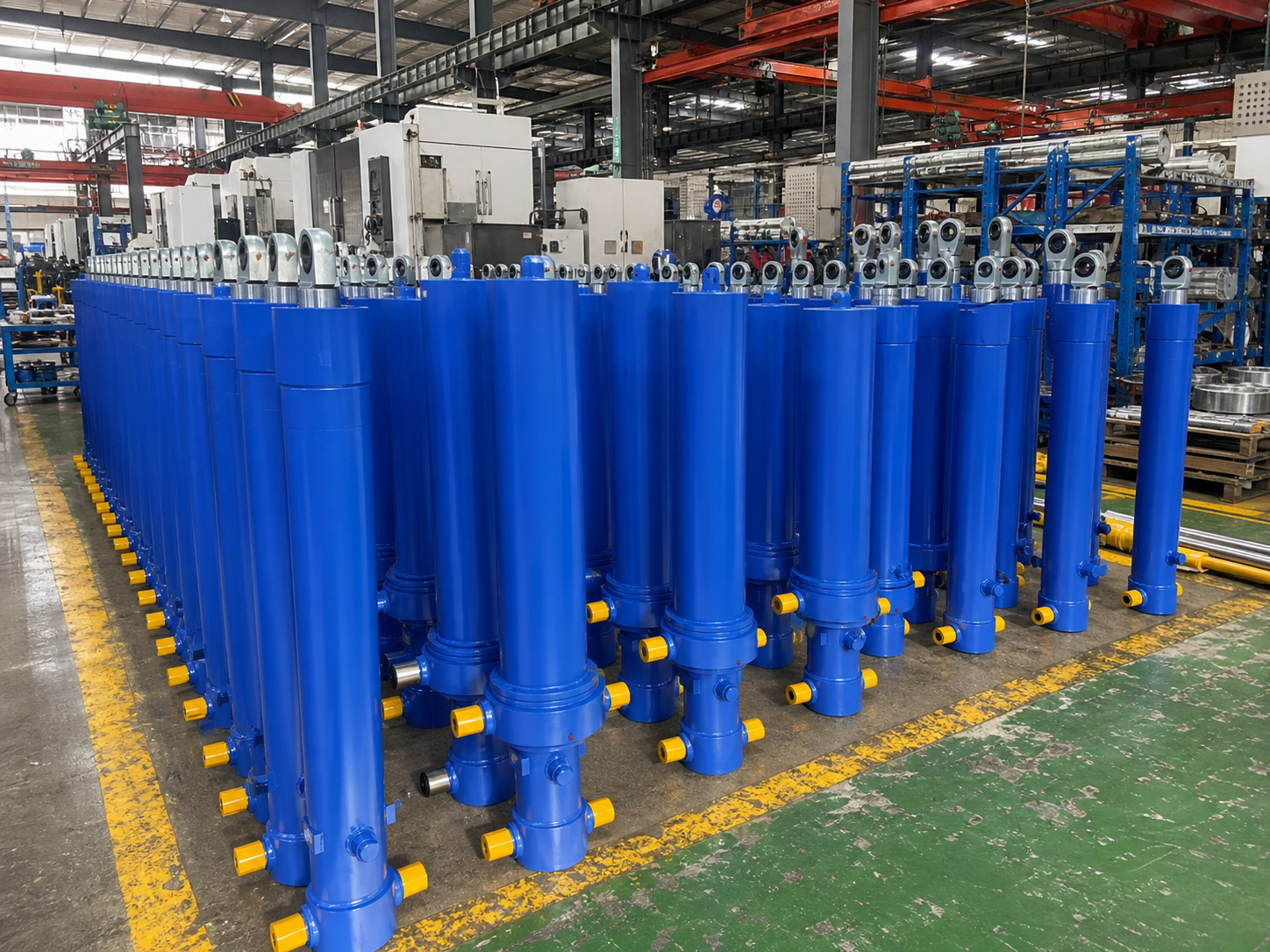
Front-End Telescopic Hydraulic Cylinder for Tipper Trucks and Tipper Trailers
الموديل: Reference Series: FC / FE / FEE Alpha Series
Reference FC Models:
FC A118-3-03880-000-K0343
FC A129-3-03880-000-K0343
FC A137-4-04980-004-K1050
FC A149-4-04660-000-K0343
FC A149-4-05180-000-K0343
FC A169-5-05830-000-K0343
FC A169-5-06230-000-K0343
FC A169-5-06480-014-K1050
FC A169-5-07130-000-K0343
FC A169-5-08130-000-K0486
FC A191-5-06830-000-K0343
Reference FE Models:
FE A129-3-03880-001-K1600
FE A149-4-04660-009-K1485
FE A149-4-04980-001-K1530
FE A169-5-06230-019-K1559
FE A1
المعلمات: Cylinder Type: Front-end multi-stage telescopic hydraulic cylinder
Actuation: Single acting
Retraction Method: Gravity and tipper-body load return
Installation Position: Front of the tipper body
Typical Application: Rear-end tipping truck or tipping semitrailer
Reference Product Lines: FC / FE / FEE Alpha Series
Number of Stages: 3–6 stages for the listed standard configurations
Effective First-Stage Diameter: 118–191 mm for the listed FC and FE configurations
FEE Effective Diameter: 169 mm for the listed representative configurations
FC Stroke Range: 3,880–8,130 mm for the listed standard models
FE Stroke Range: 3,880–7,130 mm for the listed standard models
FEE Stroke Range: 4,165–6,150 mm for the listed representative models
Broader FEE Family Stroke Range: Approximately 2,785–9,030 mm, depending on model
Maximum Working Pressure: Up to 250 bar
Typical Model-Dependent Working Pressure: 170–250 bar
Reference FC Lifting-Capacity Range: 33–79 metric tons for the listed models
Reference FE Lifting-Capacity Range: 30–61 metric tons for the listed models
Overall Front-End Cylinder Catalogue Range: 5–100 metric tons
Reference FC Oil Volume: 34–134 L, depending on model
Reference FE Oil Volume: 41–139 L, depending on model
Reference FC Cylinder Weight: 190–405 kg, depending on model
Reference FE Cylinder Weight: 142–316 kg, depending on model
FC Body Connection: Cover-type / trunnion-type mounting arrangement
FE Body Connection: Eye-type front-end mounting arrangement
FEE Body Connection: Piston eye and bottom eye with pin
Typical FC Headboard Configuration: Straight headboard
Typical FE/FEE Headboard Configuration: Slanted headboard
Duty Options: Standard Duty / Heavy Duty
Stage Surface Option: Standard finish / hard-chromed stages
Mounting Bracket Options: Maintenance-free or greased bracket configuration
Hydraulic Port: Configured according to the verified model and customer installation
Operating Medium: Mineral-based hydraulic oil or customer-specified compatible fluid
Operating Temperature: Determined by seal package, hydraulic fluid and operating environment
Replacement Identification: Original part number, complete model code, dimensions or approved drawing required
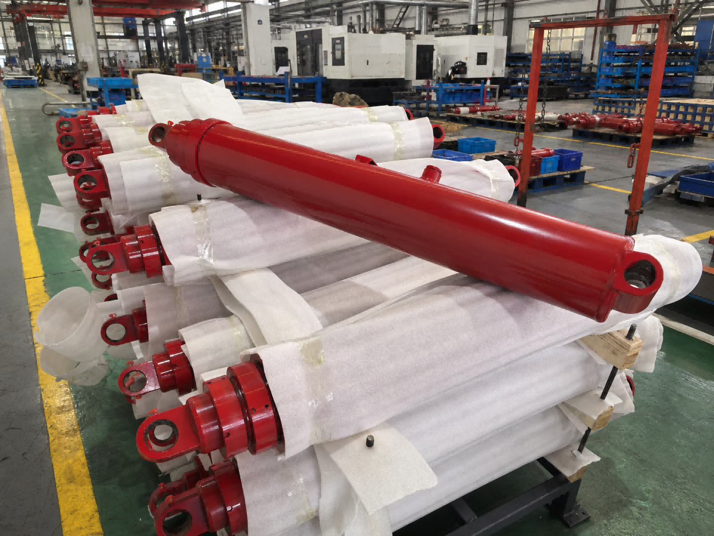
Single-Acting Telescopic Hydraulic Cylinder for Dump Trucks
الموديل: S Series Single-Acting Telescopic Cylinders
S42 Series
S43 Series
S52 Series
S53 Series
S62 Series
S63 Series
S64 Series
S73 Series
S74 Series
S84 Series
S85 Series
S95 Series
المعلمات: Acting Type: Single Acting
Retraction Method: Gravity Return or External Load Return
Cylinder Type: Multi-Stage Telescopic Cylinder
Service Class: Heavy-Duty Mobile Hydraulic Service
Number of Moving Stages: 2–5 Stages in Common Standard Dump-Cylinder Models
General Sleeve Diameter Range: 1.75–14.00 in
Standard Stocking-Model Largest Stage Class: Approximately 5–8 in
General Stroke Range: 36–500 in
Current Stocking-Model Stroke Range: 72–265 in
Nominal Working Pressure: 2,000 PSI
Nominal Working Pressure: 140 Bar
Higher Pressure Application: Subject to Engineering Evaluation
Standard Hydraulic Medium: Filtered Mineral-Based Hydraulic Oil
Standard Operating Temperature: −40°F to +200°F
Standard Operating Temperature: Approximately −40°C to +93°C
Standard Mounting: Pin-Mounted Base and Plunger End
Available Mounting Codes: CC, DB, DC and MB
Standard Port Options: NPT or SAE O-Ring Boss, Depending on Model
Typical Port Sizes: 1/2 in NPT, 3/4 in NPT, 1 in NPT, #8 SAE, #12 SAE or #16 SAE
Extension Sequence: Largest Moving Stage Extends First
Retraction Sequence: Smallest Moving Stage Retracts First
Standard Dump Angle Range: Approximately 45–57 Degrees
Surface Finish: Corrosion-Resistant Industrial Coating
Manufacturing Basis: Verified Model Number, 10-Digit Part Number or Approved Drawing
Quality Inspection: Dimensional Inspection, Stage Sequence Testing, Pressure Testing and Leakage Testing
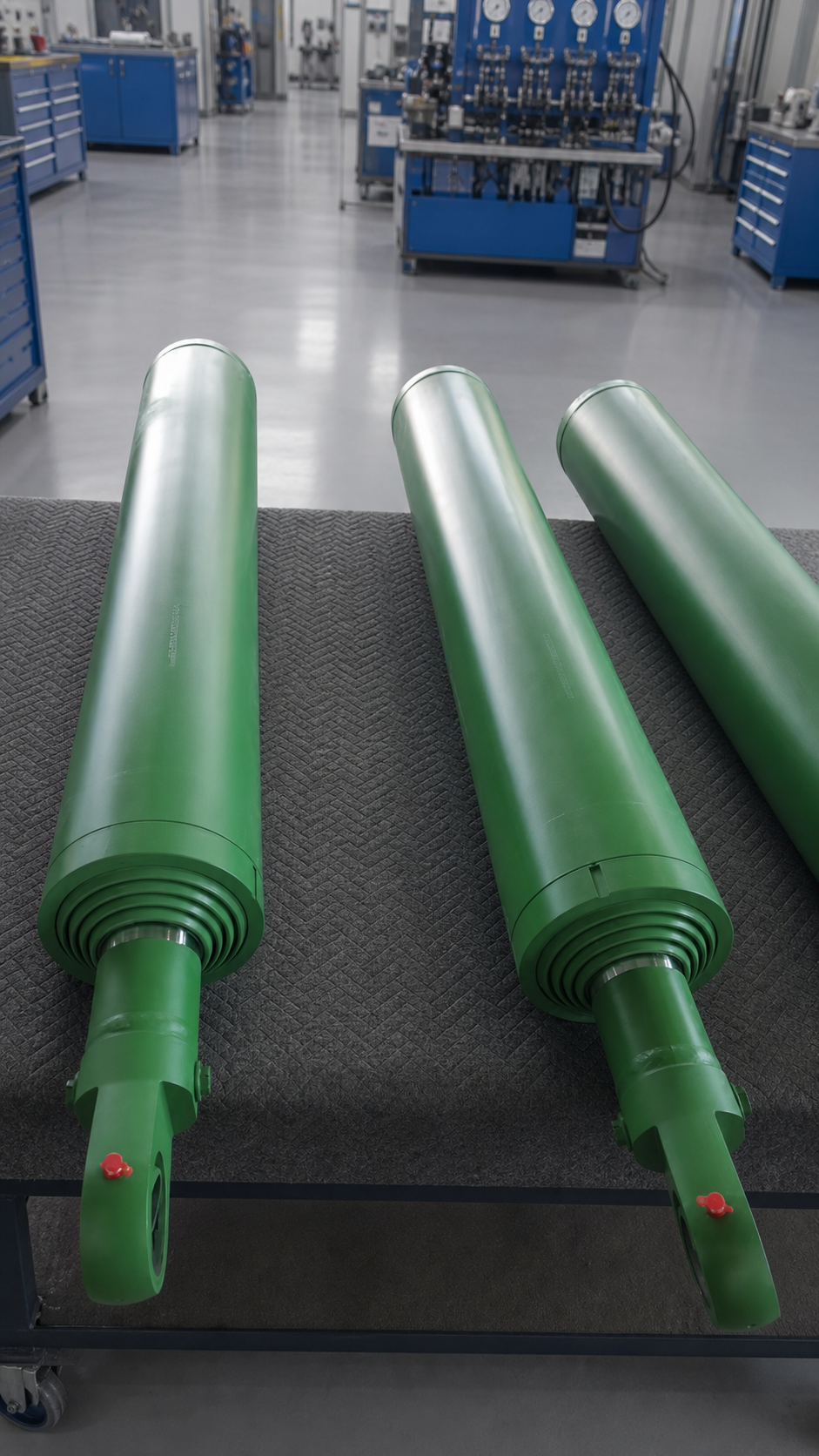
Refuse Truck Replacement Hydraulic Cylinder
الموديل: HEIL Replacement Cylinder — Made to Verified Part Number
McNeilus Replacement Cylinder — Made to Verified Part Number
New Way Replacement Cylinder — Made to Verified Part Number
Labrie Replacement Cylinder — Made to Verified Part Number
All manufacturer names, equipment models and OEM part numbers are used solely for product identification and cross-reference purposes. Apex Hydraulic replacement cylinders are independently manufactured products and are not represented as original parts unless e
المعلمات: Acting Type: Single Acting or Double Acting, Depending on OEM Part Number
Cylinder Structure: Welded Cylinder or Telescopic Cylinder, Depending on Application
Bore Diameter: Manufactured According to Verified OEM Part Number or Approved Drawing
Rod Diameter: Manufactured According to Verified OEM Part Number or Approved Drawing
Stroke Length: Manufactured According to Verified OEM Part Number or Approved Drawing
Retracted Length: Matched to Original Equipment Installation Dimensions
Extended Length: Matched to Original Equipment Operating Requirements
Working Pressure: According to Original Equipment Hydraulic System Requirements
Mounting Style: Pin-Eye, Clevis, Trunnion or Application-Specific Mounting
Port Type: SAE O-Ring Boss or Application-Specific Hydraulic Port
Port Position: Matched to Original Installation Orientation
Integrated Valve: Optional Counterbalance, Holding or Cushion Valve According to Part Number
Cushioning: Optional End-of-Stroke Cushioning
Position Sensor: Optional, Depending on Equipment Configuration
Surface Finish: Corrosion-Resistant Industrial Coating
Identification Method: OEM Part Number, Equipment Model, Drawing or Physical Sample
Quality Inspection: Dimensional Inspection, Pressure Testing, Leakage Testing and Functional Testing
Replacement Requirement: Final Compatibility Confirmed Before Production
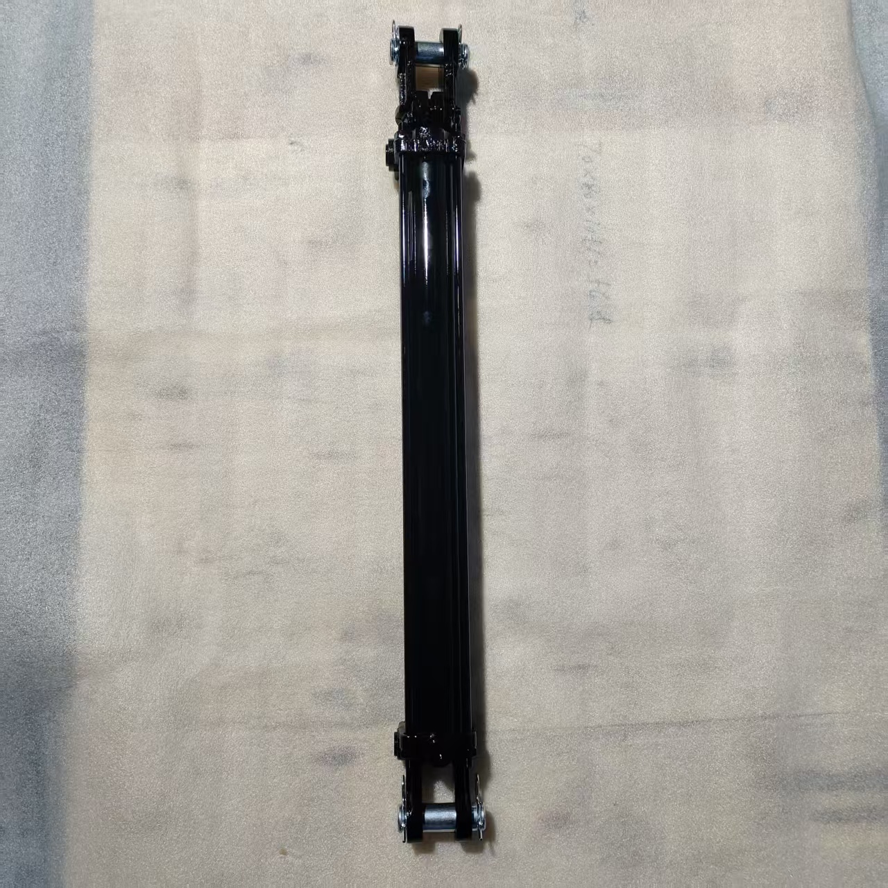
Tie-Rod Hydraulic Cylinder
الموديل: HTR Series
HTH Series
المعلمات: Acting Type: Double Acting
Cylinder Construction: Tie-Rod Construction
HTR Rated Working Pressure: 2,500 PSI
HTH Rated Working Pressure: 3,000 PSI
Bore Diameter Range: 2–5 in
HTR Stroke Range: 4–36 in
HTH Stroke Range: 4–48 in
Rod Diameter Range: 1.125–2 in
Mounting Configuration: Adjustable Threaded Female Clevis
Port Configuration: SAE O-Ring Boss Ports
Port Arrangement: Two Ports Positioned at 90 Degrees
Rod Surface: Hard Chrome Plated
Chrome Plating Thickness: Approximately 0.001 in
Final Rod Surface Hardness: Approximately 69–71 HRC
HTH Rod Core Hardness: Approximately 45–50 HRC
Standard Paint Color: Black
Operating Medium: Mineral-Based Hydraulic Oil
Customization: Bore, Stroke, Rod Diameter, Ports, Mounting and Paint Available by Agreement
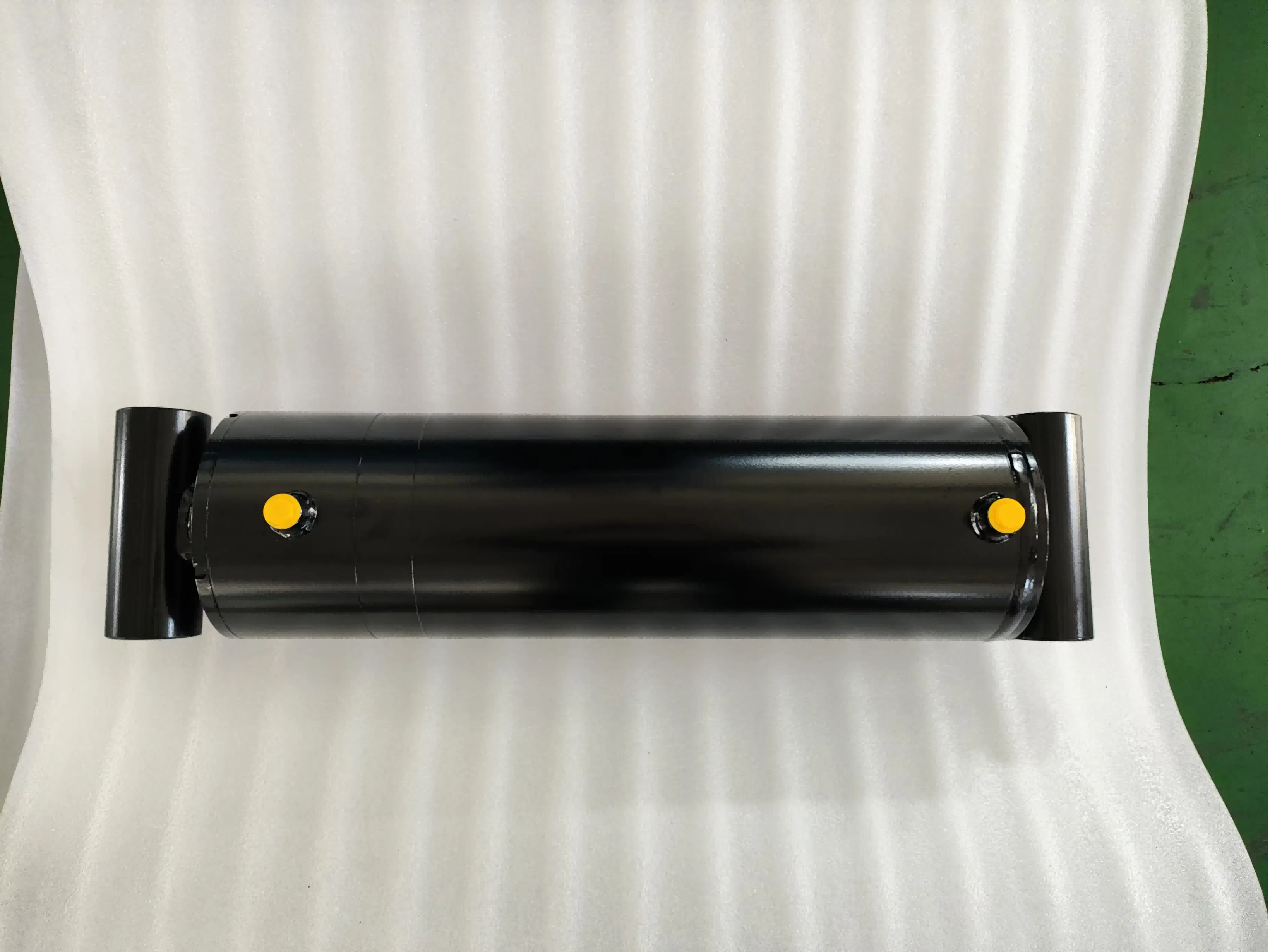
Welded Hydraulic Cylinder
الموديل: HBU Series, HCL Series and HTG Series
المعلمات: Acting Type: Double Acting
Rated Working Pressure: Up to 3,000 PSI
HBU Bore Diameter Range: 1.5–5.0 in
HBU Stroke Range: 4–48 in
HBU Rod Diameter Range: 1.0–2.5 in
HBU Retracted Length Range: 12–60 in
HBU Bushing Inside Diameter Range: 0.75–1.75 in
HBU Mounting Style: Cross-Tube Bushing Mount
HCL Bore Diameter Range: 1.5–5.0 in
HCL Stroke Range: 4–36 in
HCL Rod Diameter Range: 1.25–2.5 in
HCL Retracted Length Range: 14.25–48.25 in
HCL Pin Diameter Options: 1.0, 1.25 and 1.5 in
HCL Mounting Style: Fixed Clevis Mount
HTG Bore Diameter Range: 2.0–4.0 in
HTG Stroke Range: 4–36 in
HTG Rod Diameter Range: 1.125–1.75 in
HTG Retracted Length Range: 14.25–46.25 in
HTG Pin Diameter: 1.0 in
HTG Mounting Style: Adjustable Threaded Female Clevis with Locking Bolt
Standard Hydraulic Ports: SAE O-Ring Boss
Optional Hydraulic Ports: NPT, subject to model and order confirmation
Gland Construction: Threaded and Serviceable
Standard Finish: Black Industrial Coating
Installation Dimensions: Subject to the selected cross-reference model and approved production drawing
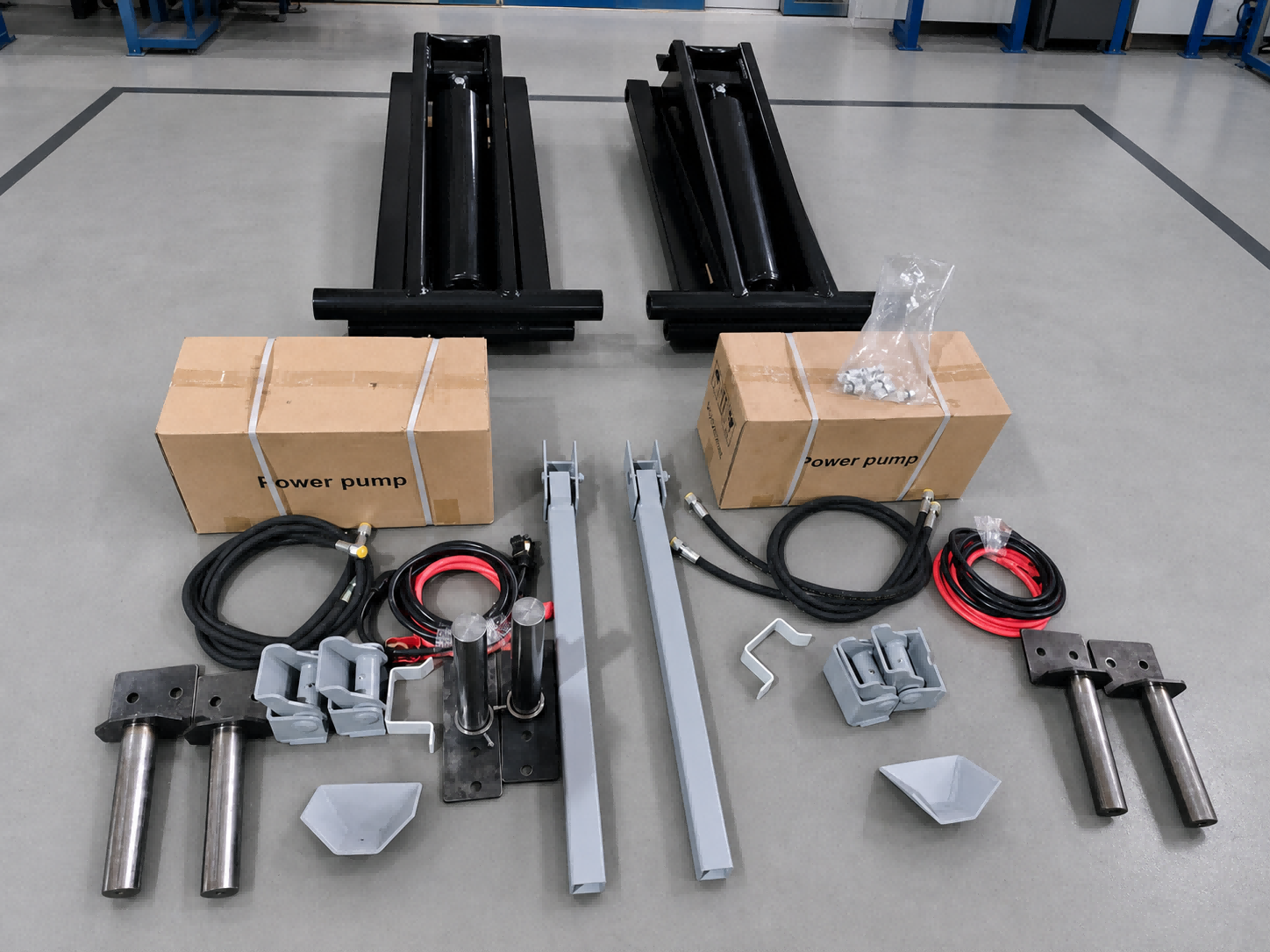
Hydraulic Scissor Hoist Kit for Dump Trailers
الموديل: PH310,PH416,PH516,PH520,PH616,PH625
المعلمات: Cross-Reference Models: PH310,PH416,PH516,PH520,PH616,PH625
Rated Hoist Capacity: 3–12 Tons (6,000–26,000 lbs), depending on model and installation geometry
Recommended Dump Body Length: 8–24 ft
Hydraulic Cylinder Diameter: 3.5–6.5 in
Cylinder Stroke Range: 10–30 in
Published Cylinder Wall Thickness: 7.5–10 mm for applicable models
Acting Type: Double Acting
Control Options: Power Up/Power Down or Power Up/Gravity Down, depending on power-unit configuration
Power Unit Options: 12V DC or 24V DC
Typical System Components: Scissor Hoist Frame, Hydraulic Cylinder, Mounting Brackets, Rear Hinges, Hydraulic Hose and Fittings, Safety Support Bar, Load Control Valve, DC Hydraulic Power Unit and Pendant Remote
Final Capacity, Dump Angle and Mounting Position: Subject to dump-body length, rear overhang, hinge position, hoist placement, hydraulic pressure and trailer-frame geometry.
PH310: 3-Ton Capacity; 3.5-in Cylinder Diameter; 10-in Stroke; 7.5-mm Cylinder Wall; Recommended for 8–10 ft Dump Bodies.
PH416: 6-Ton Rated Capacity; 5.5-in Cylinder Diameter; 16-in Stroke; 7.5-mm Cylinder Wall; Recommended for 10–14 ft Dump Bodies.
PH516: 8-Ton Rated Capacity; 5.5-in Cylinder Diameter; 16-in Stroke; 7.5-mm Cylinder Wall; Recommended for 10–14 ft Dump Bodies.
PH520: 10-Ton Rated Capacity; 5.5-in Cylinder Diameter; 20-in Stroke; 7.5-mm Cylinder Wall; Recommended for 12–16 ft Dump Bodies.
PH616-6: 11-Ton Capacity; 6.5-in Cylinder Diameter; 16-in Stroke; 10-mm Cylinder Wall; Recommended for 12–16 ft Dump Bodies.
PH625: 12-Ton Heavy-Duty Configuration; 25-in Stroke; Recommended for 16–20 ft Dump Bodies. Cylinder diameter and other dimensions must be confirmed against the approved drawing before publication.
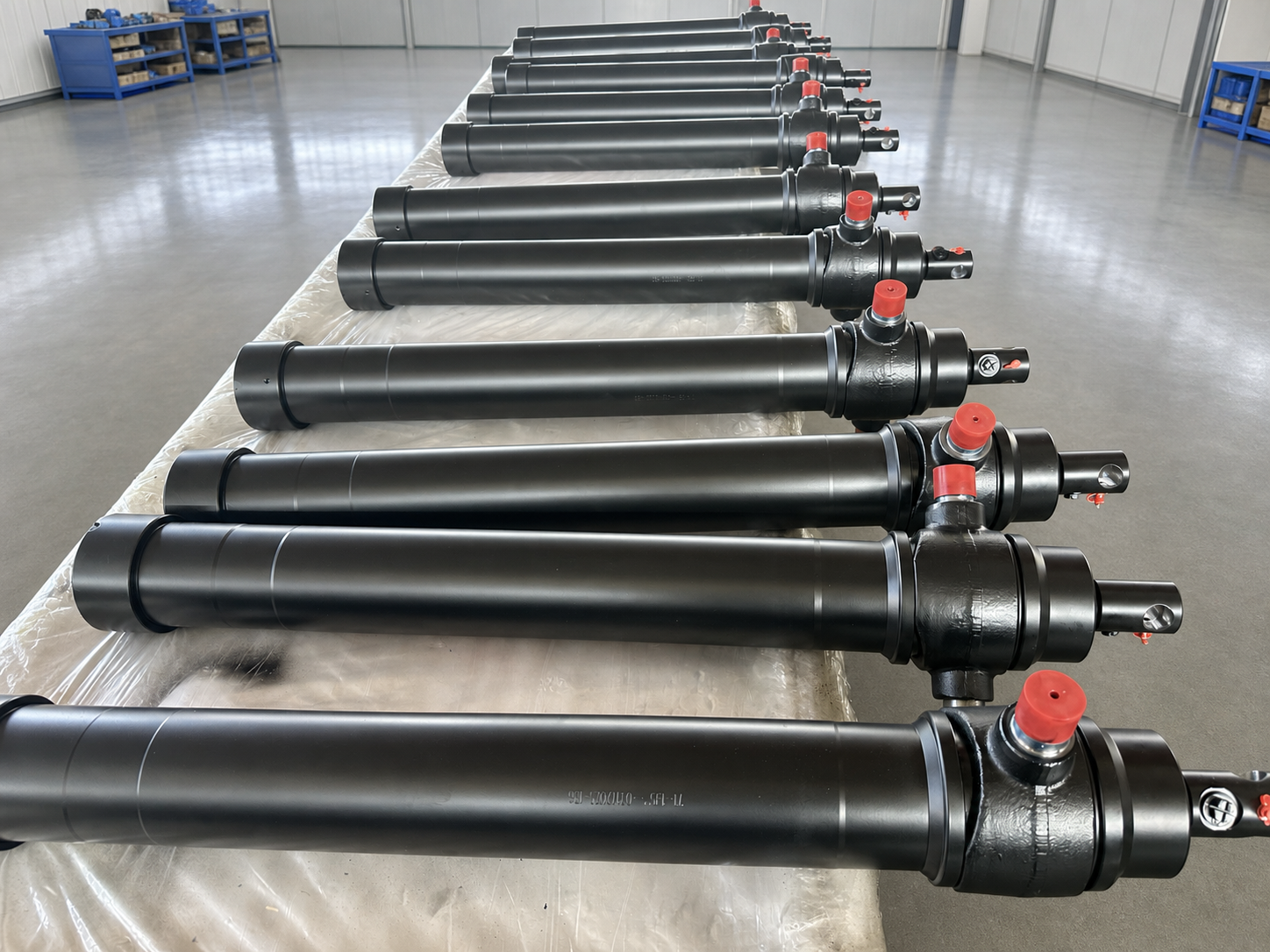
Inverted Telescopic Hydraulic Cylinder for Dump Trailers
الموديل: Apex HTC-Compatible Series
المعلمات: Cylinder Type:Single-Acting Inverted Telescopic Cylinder
Working Pressure: 3,000 PSI
Capacity:7 Ton / 12 Ton
Stroke Options:78", 90", 108", 120",144"
Retracted Length: 34.75''- 48.75''
Final Stage / Rod Diameter: 2.00"
Rod Pin Hole:1.00"
Port Options:1/2" NPT or SAE #8 ORB
Oil Capacity: 1.6–3.8 US Gallons
Mounting Style:Front-Mount Inverted Installation
Retraction Method:Gravity Return
Product Weight: 68–143 lbs
Installation Position:Front-mounted between trailer frame and dump body
Customization:Stroke, mounting, port, capacity and connection dimensions available
معرض الشركة
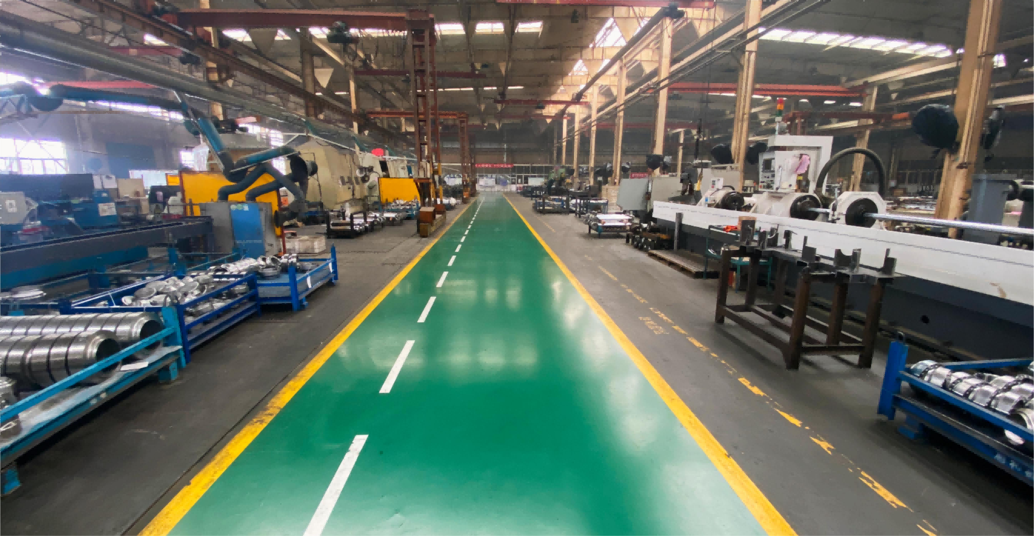
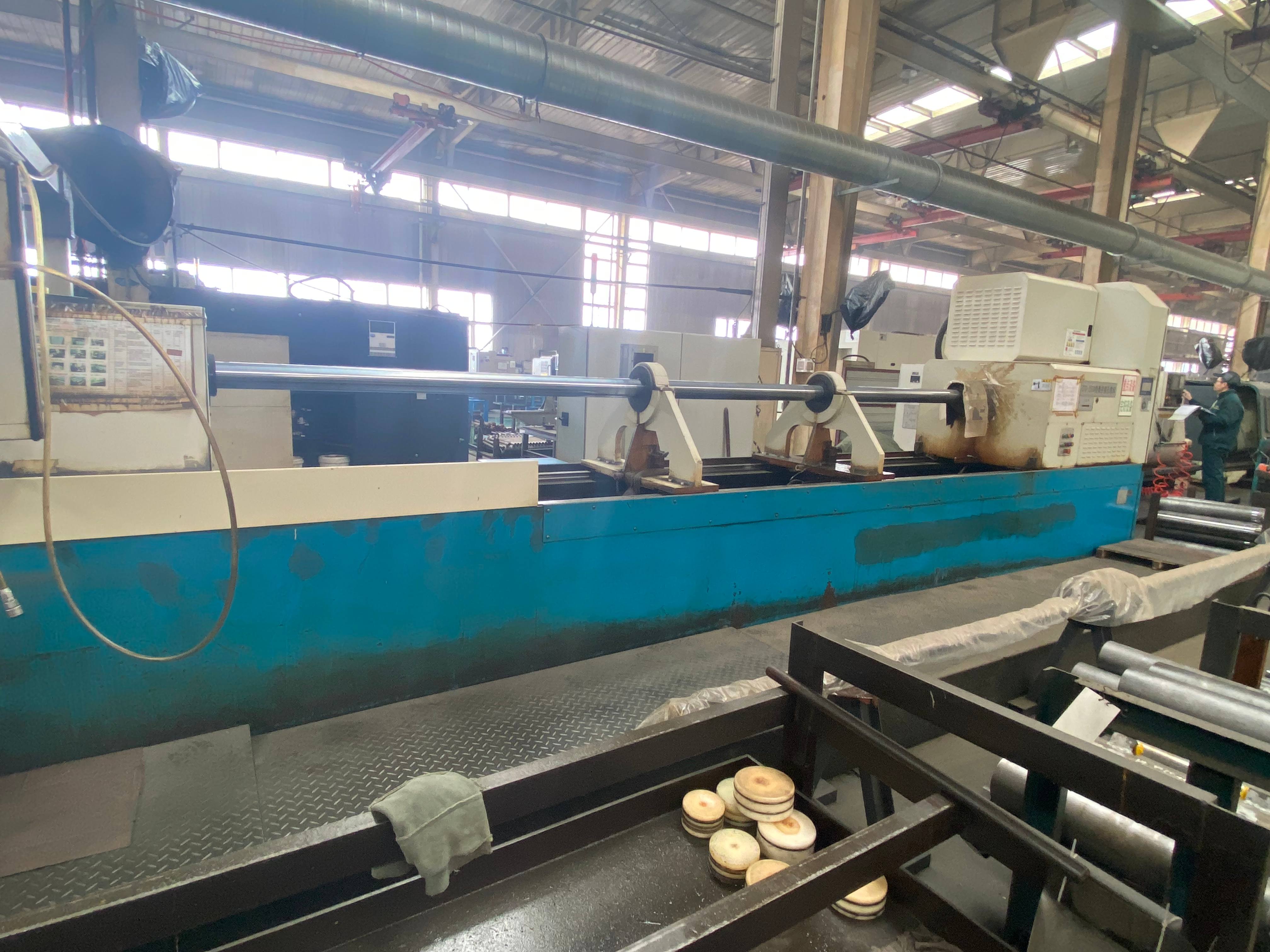
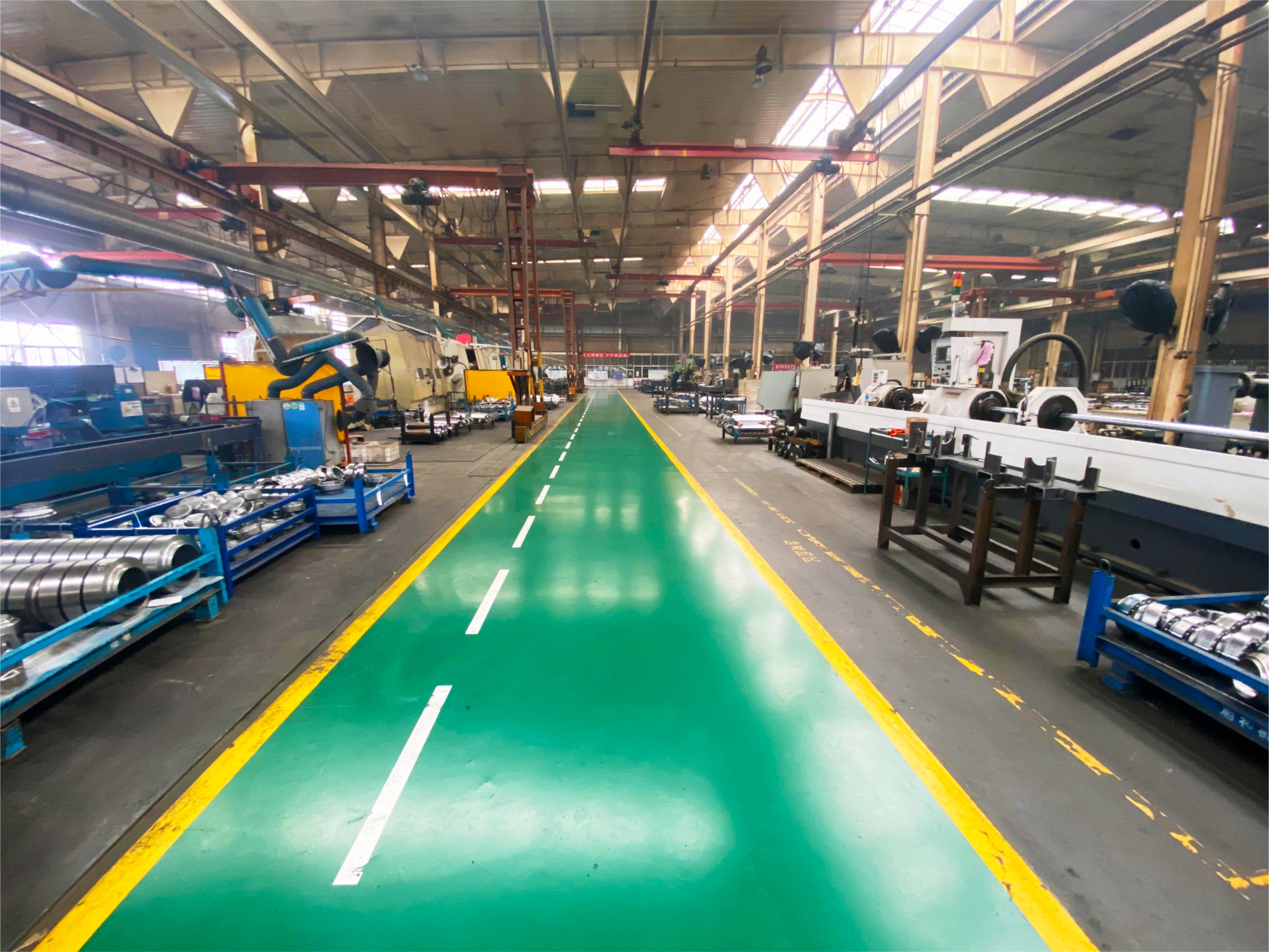
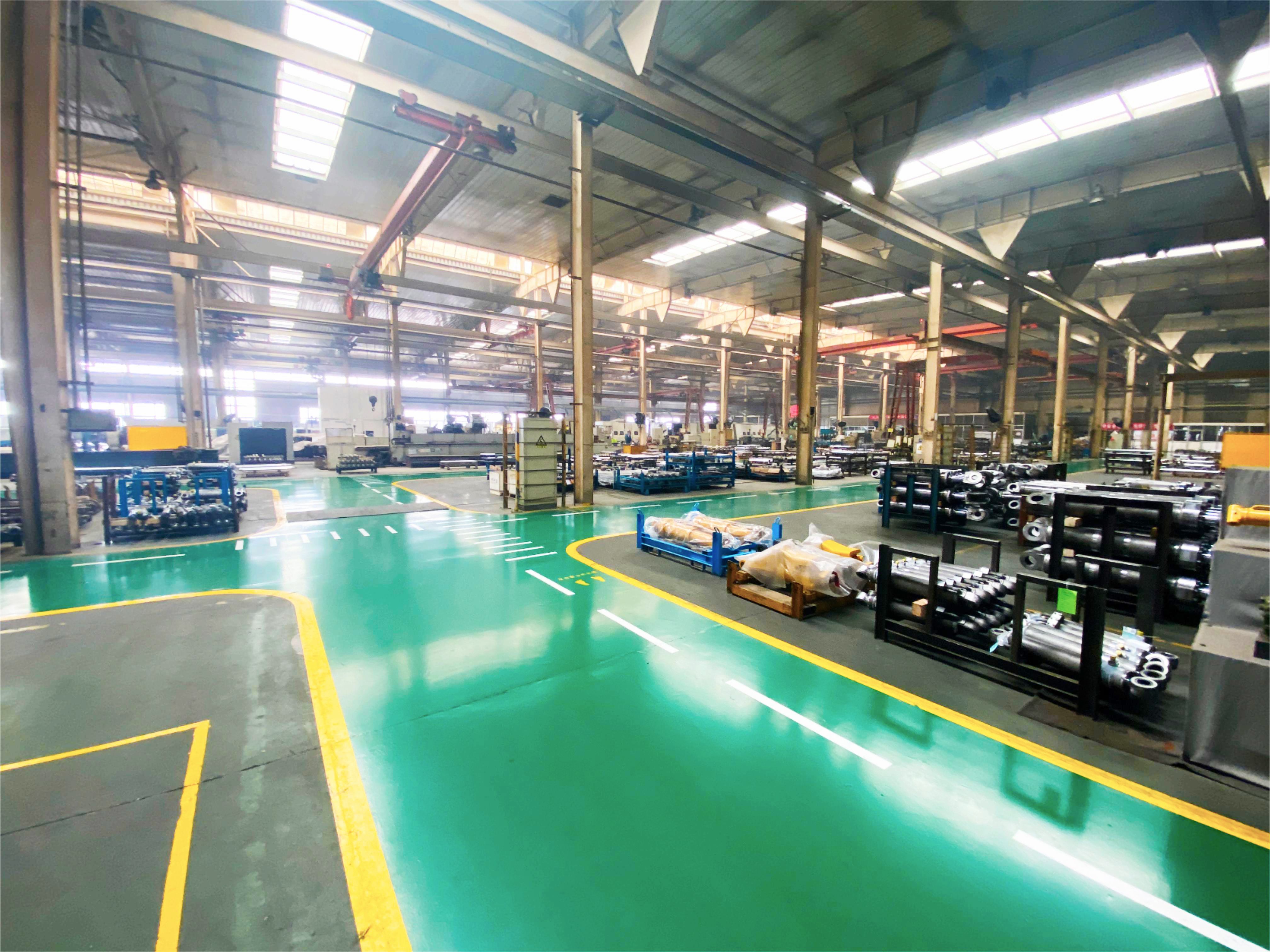
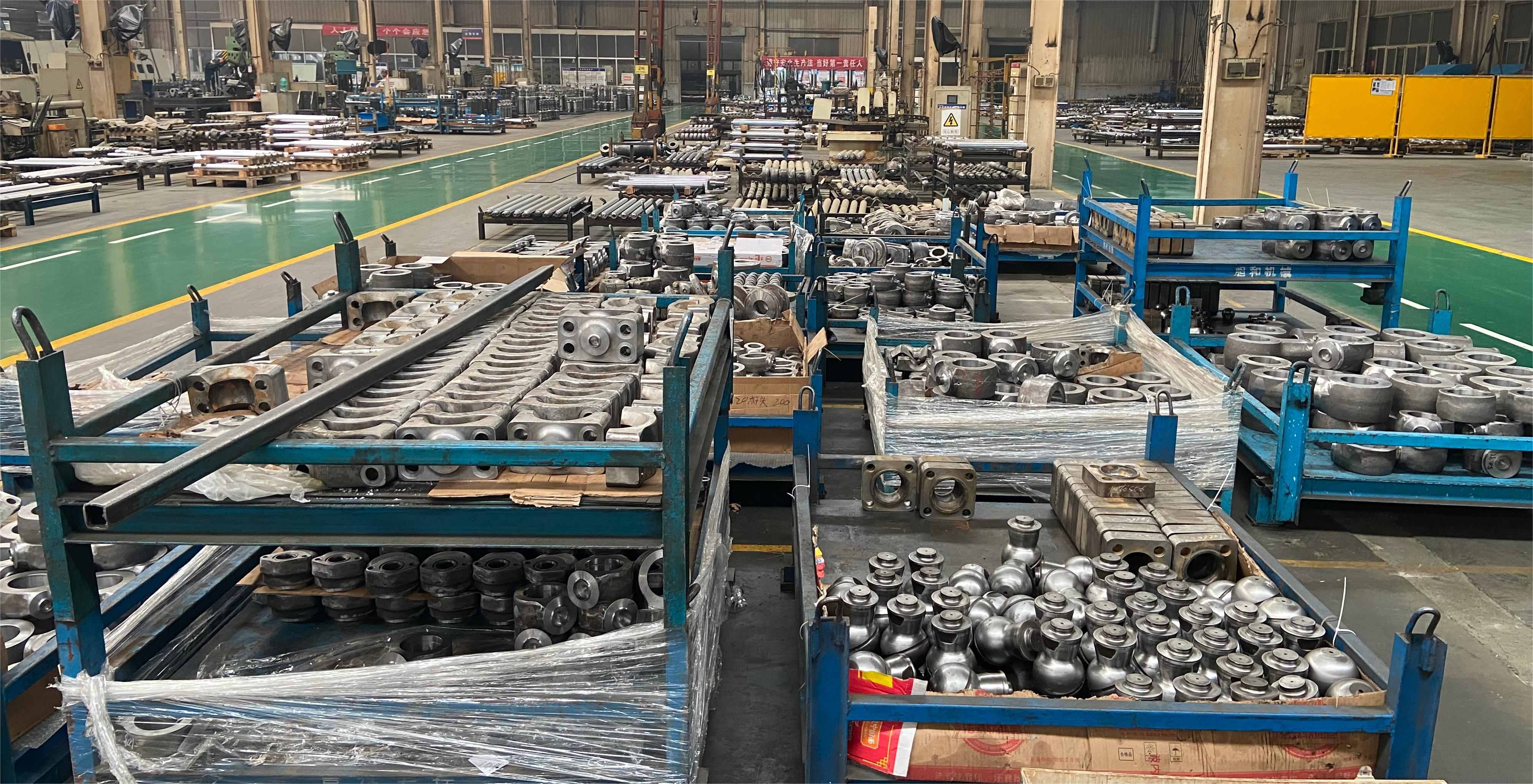
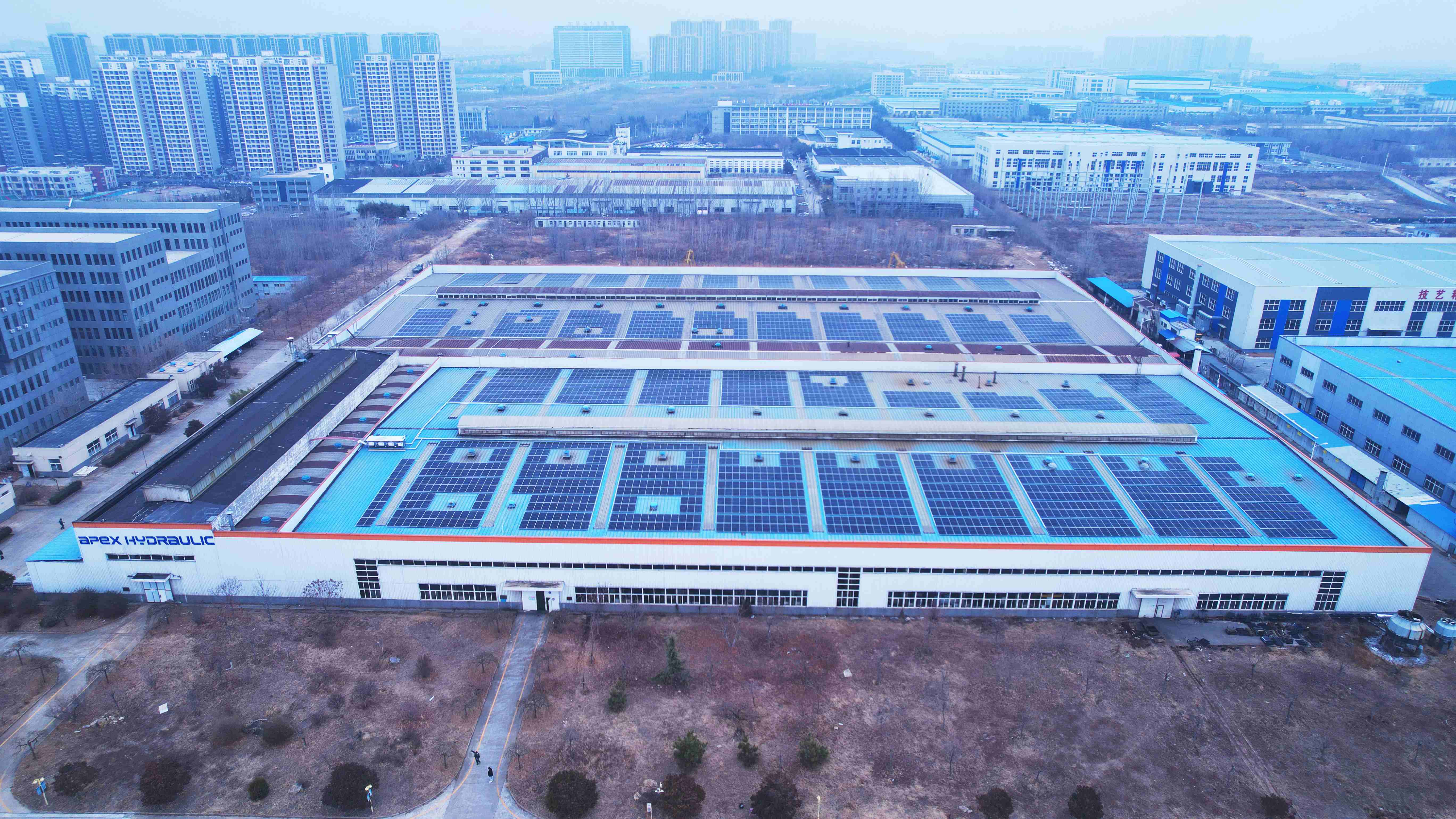
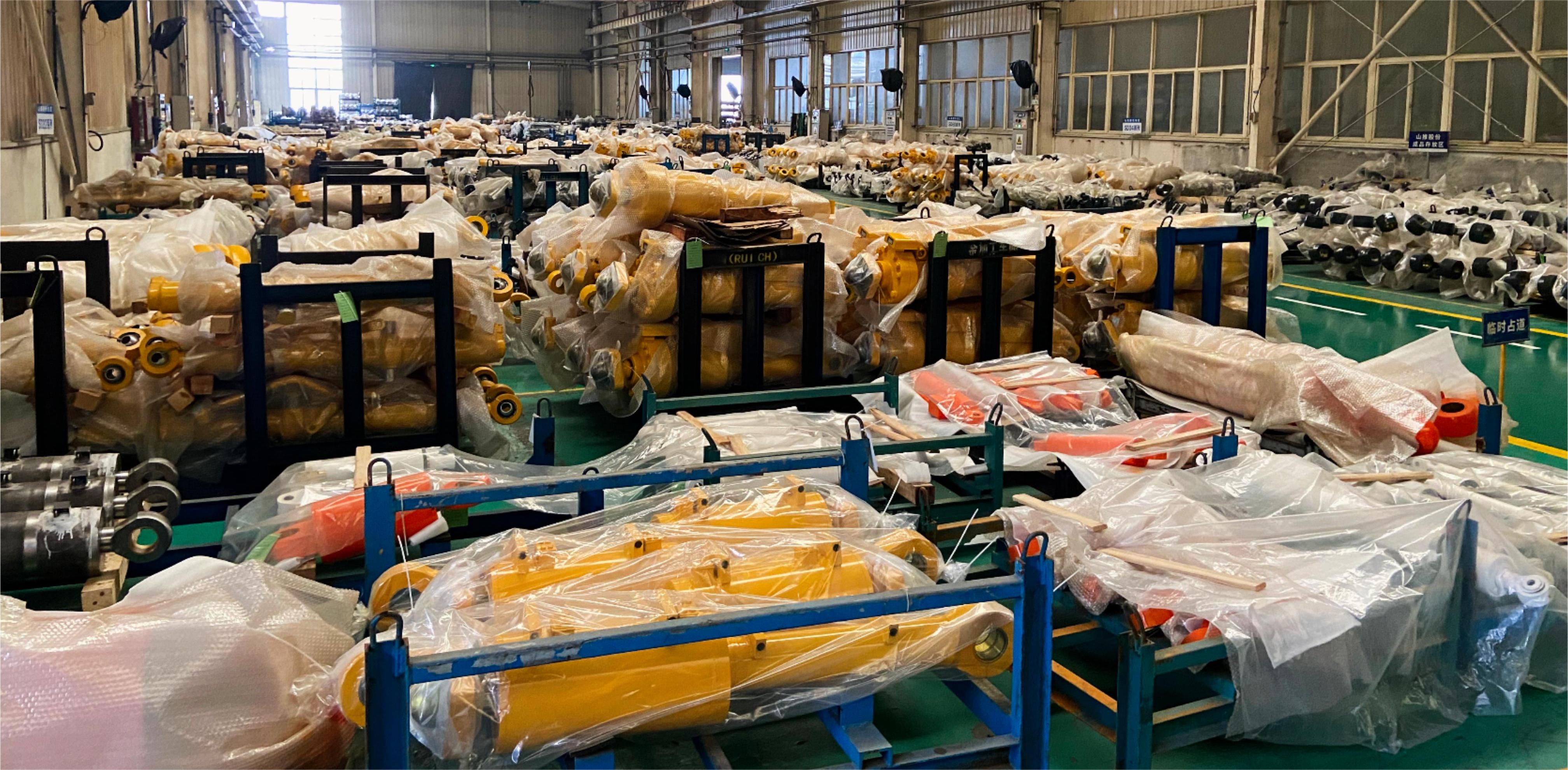
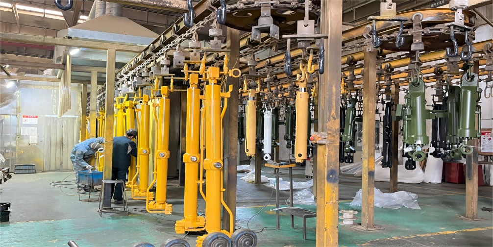
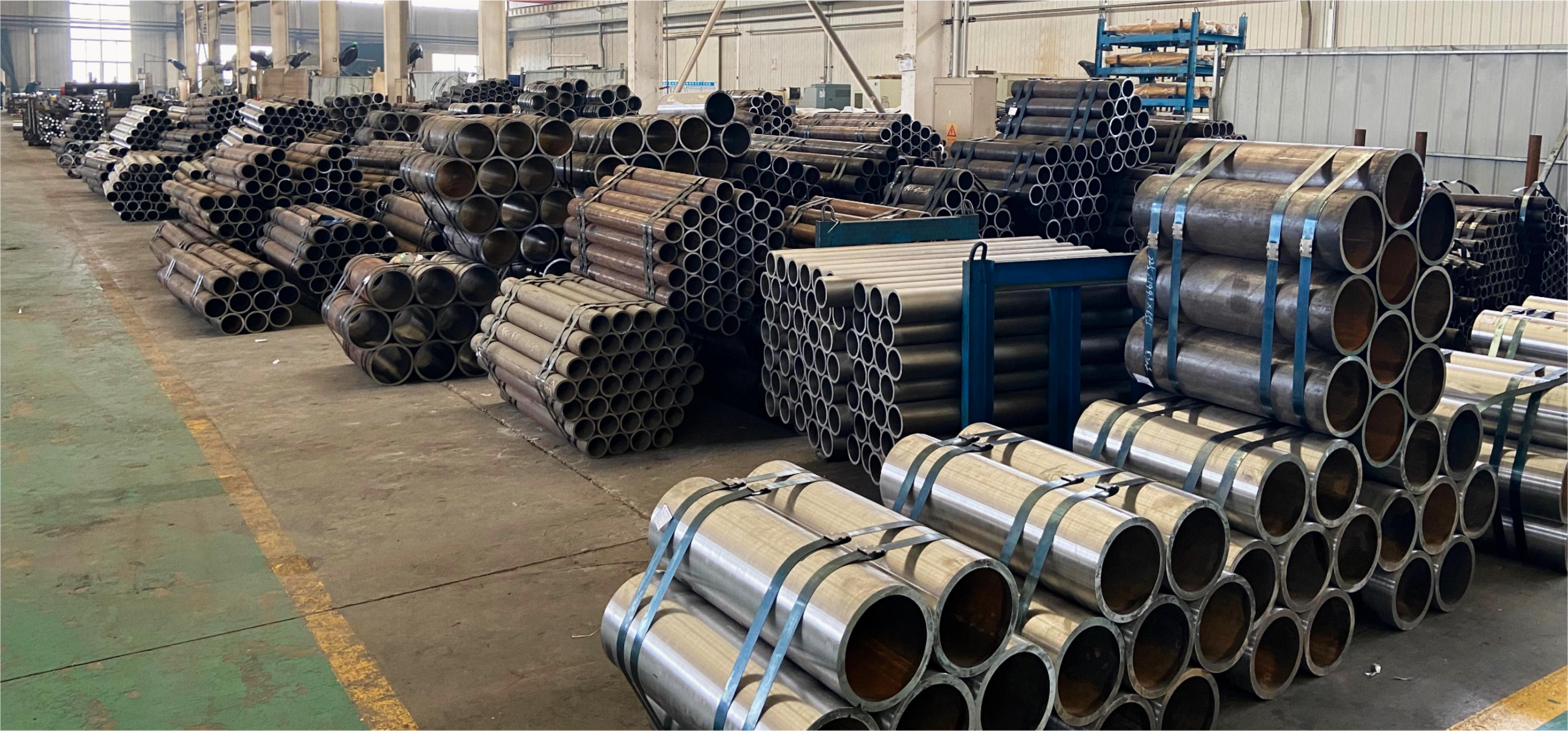
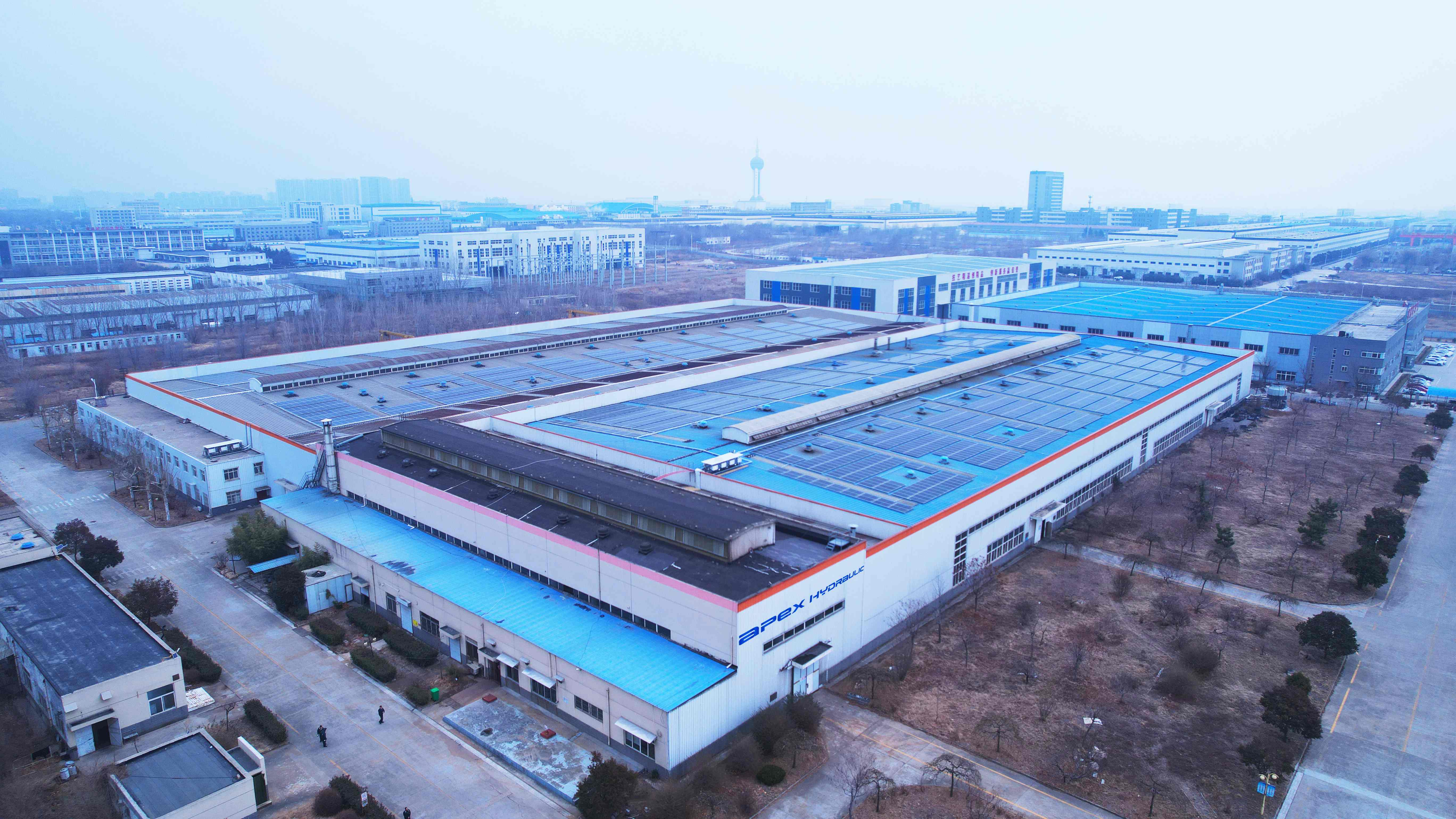
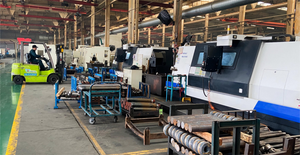
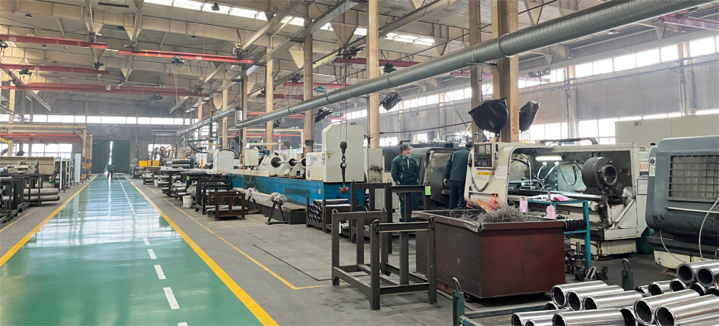
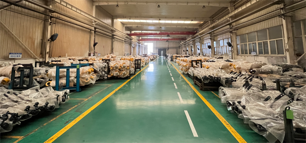
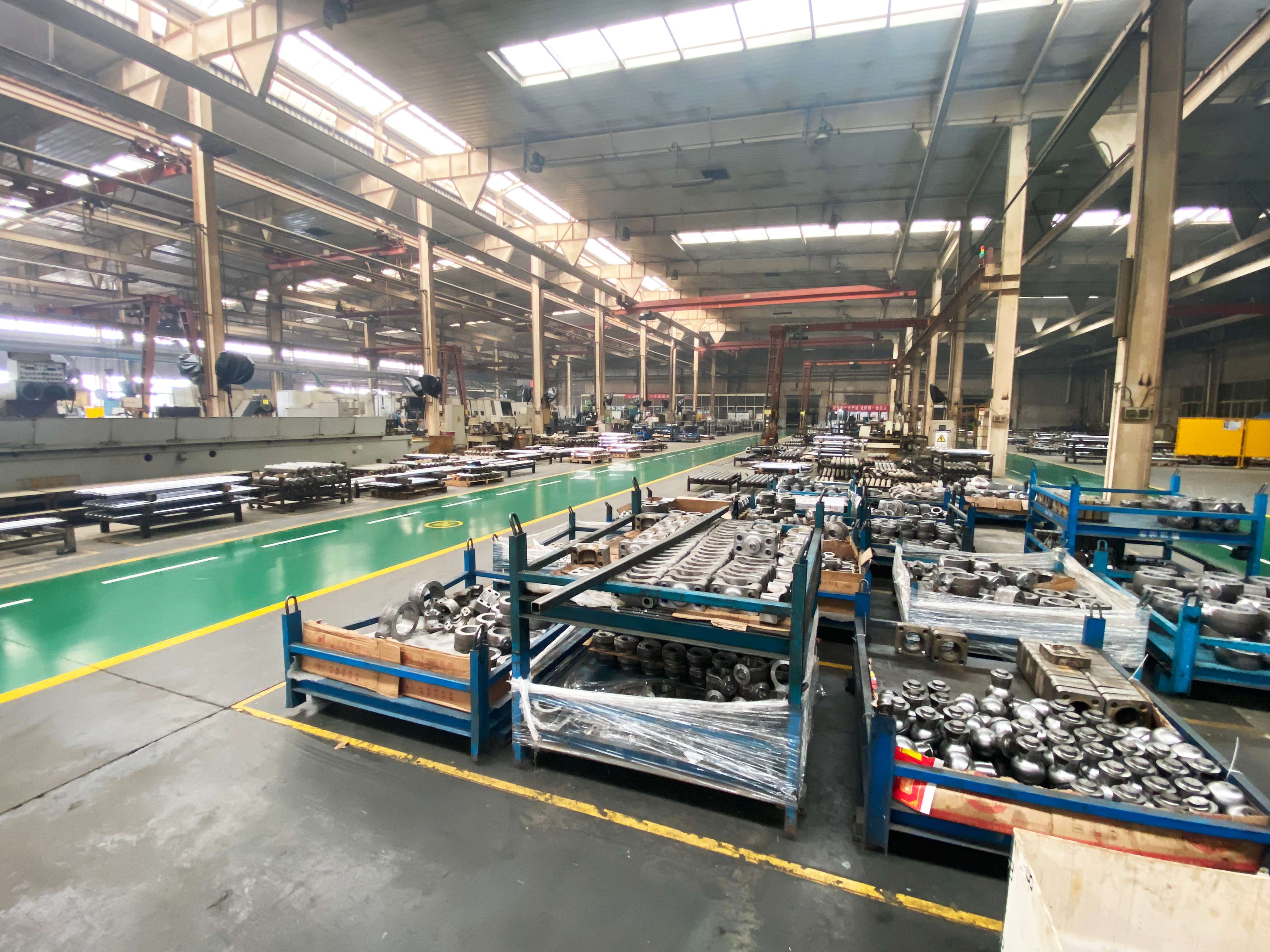
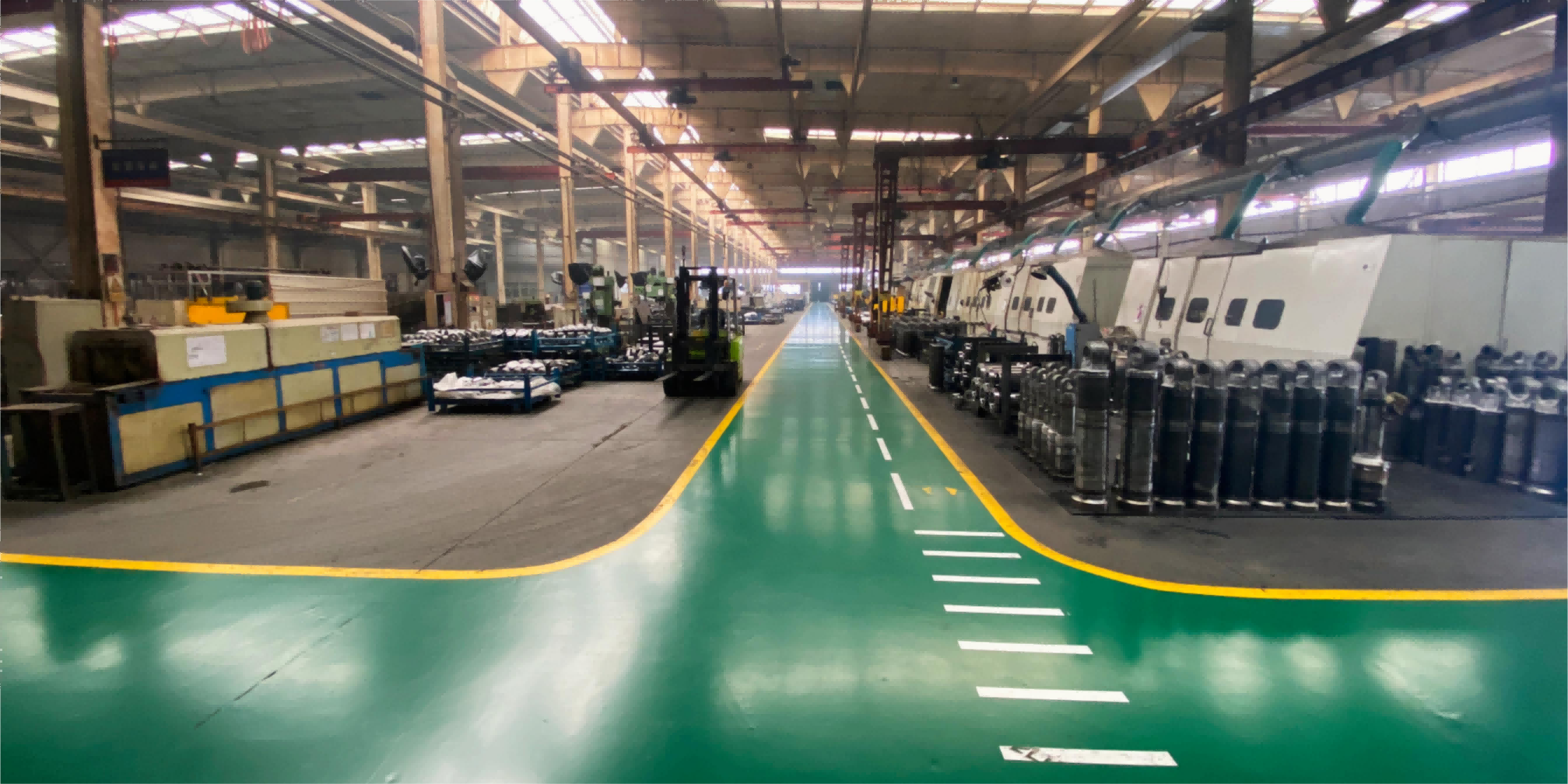
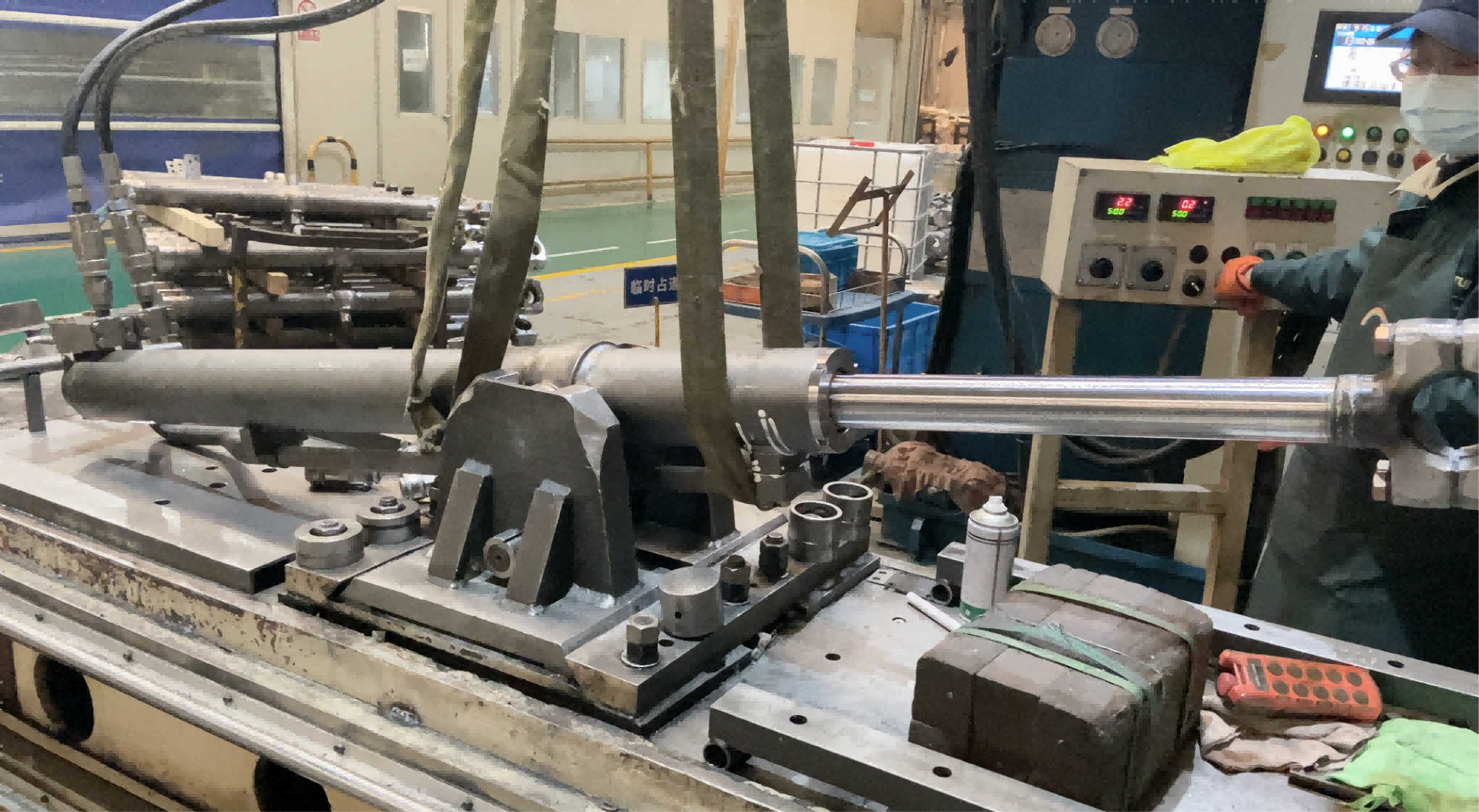
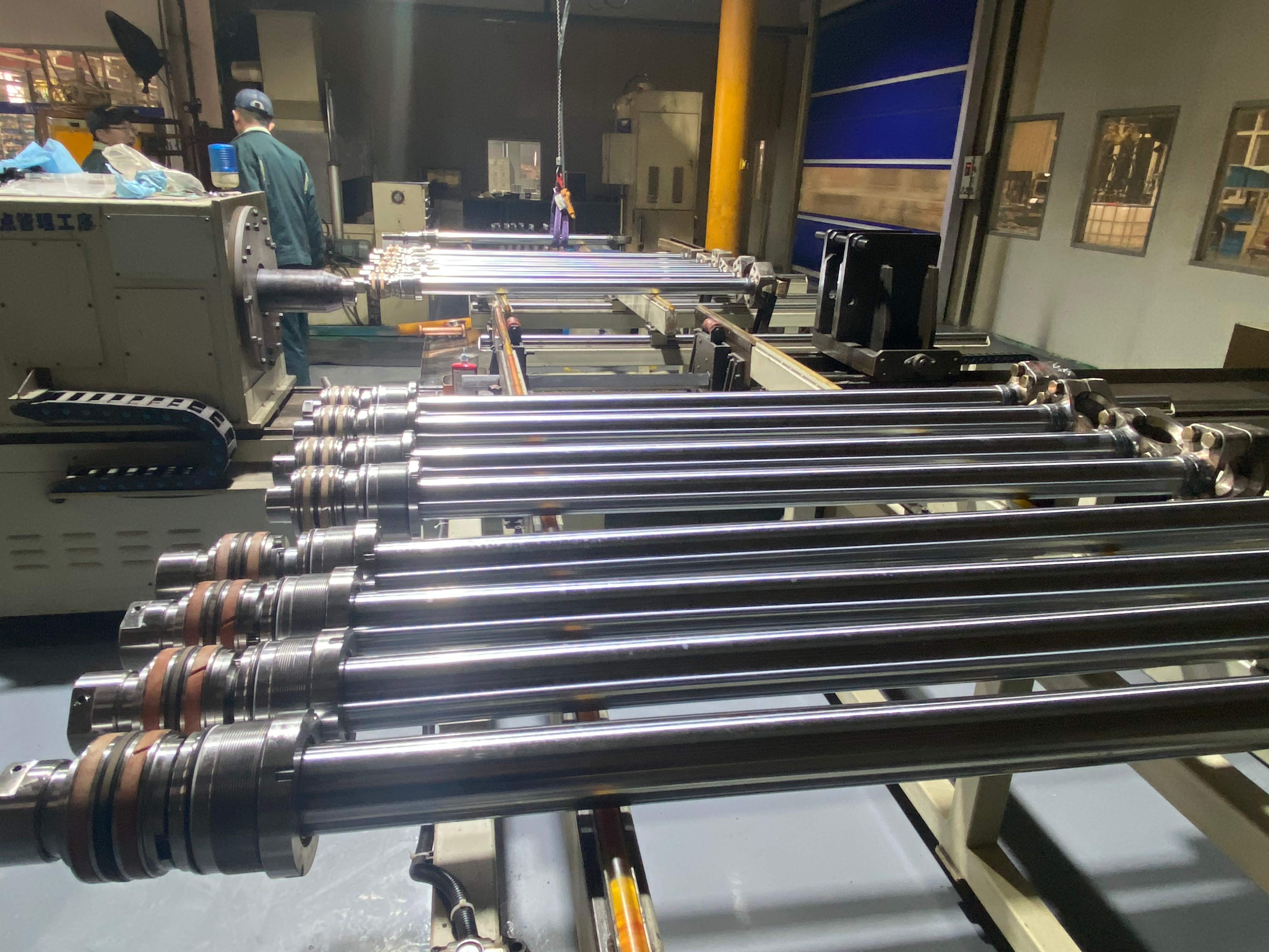
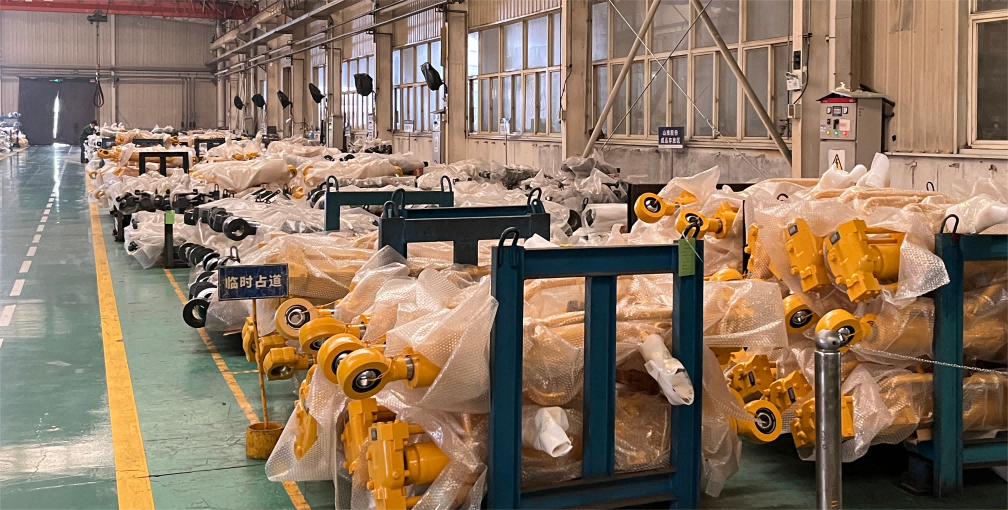
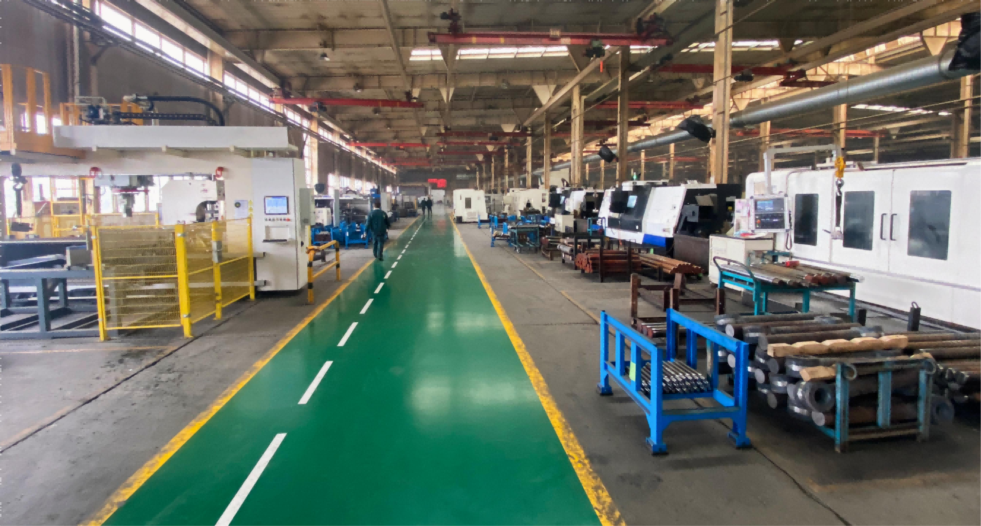
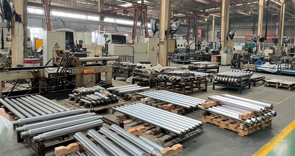
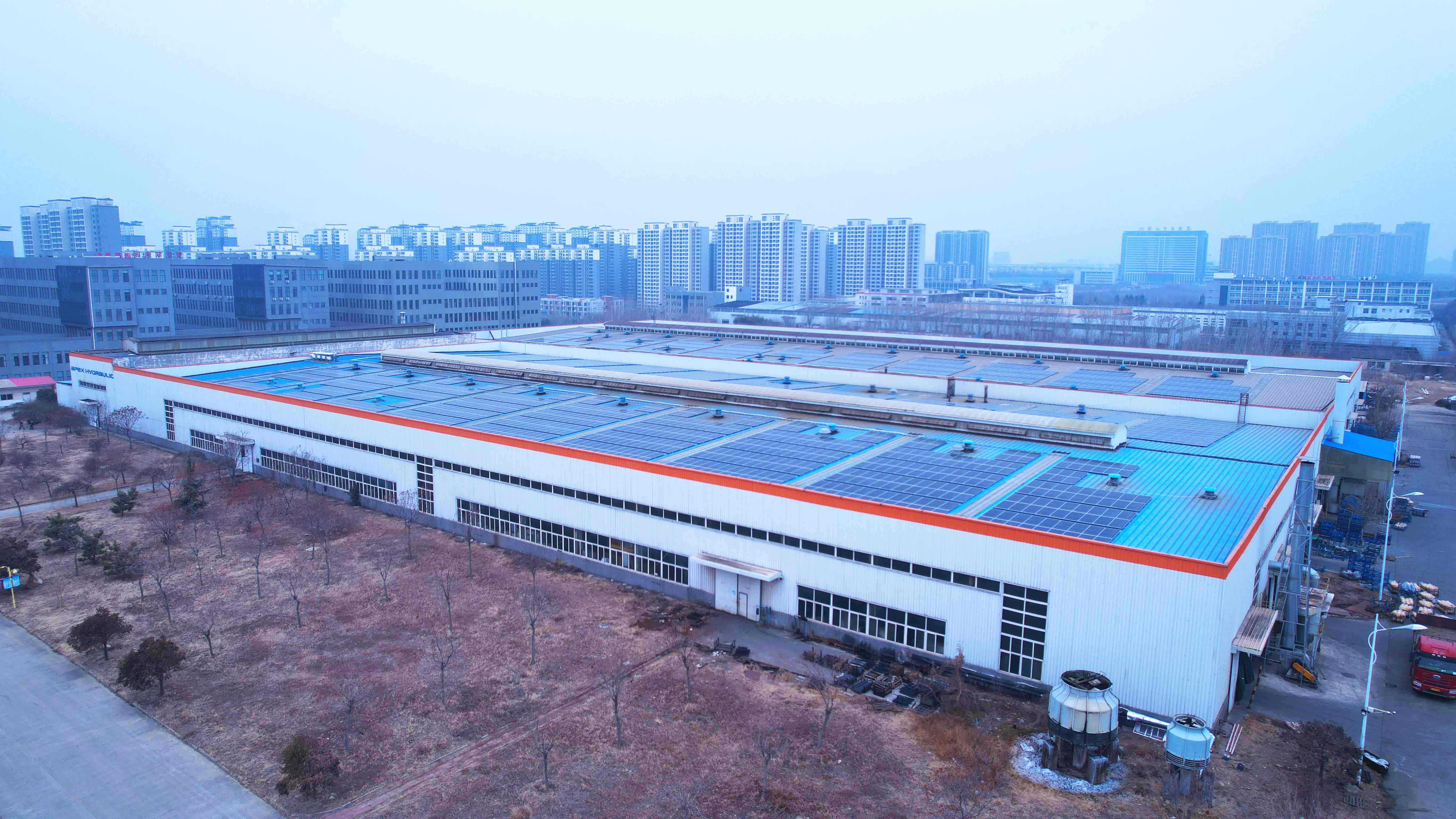
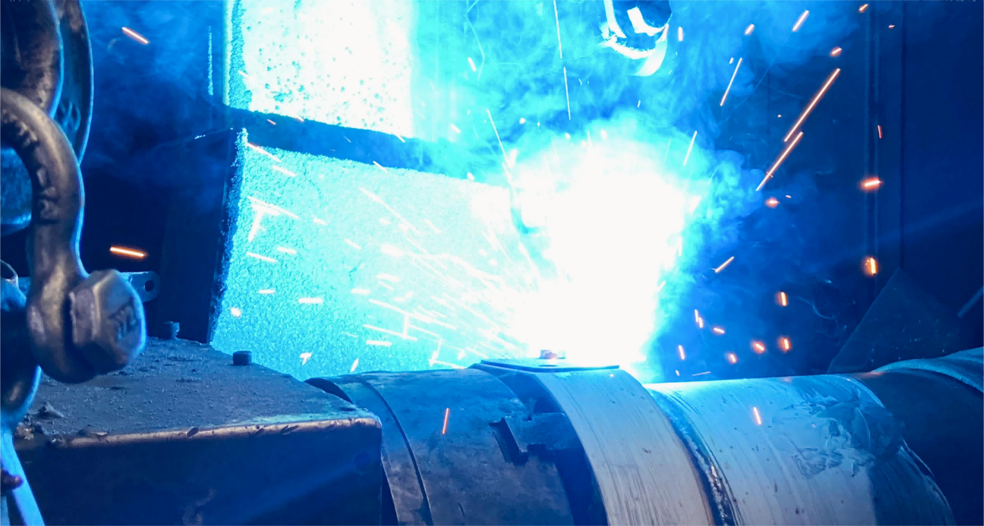
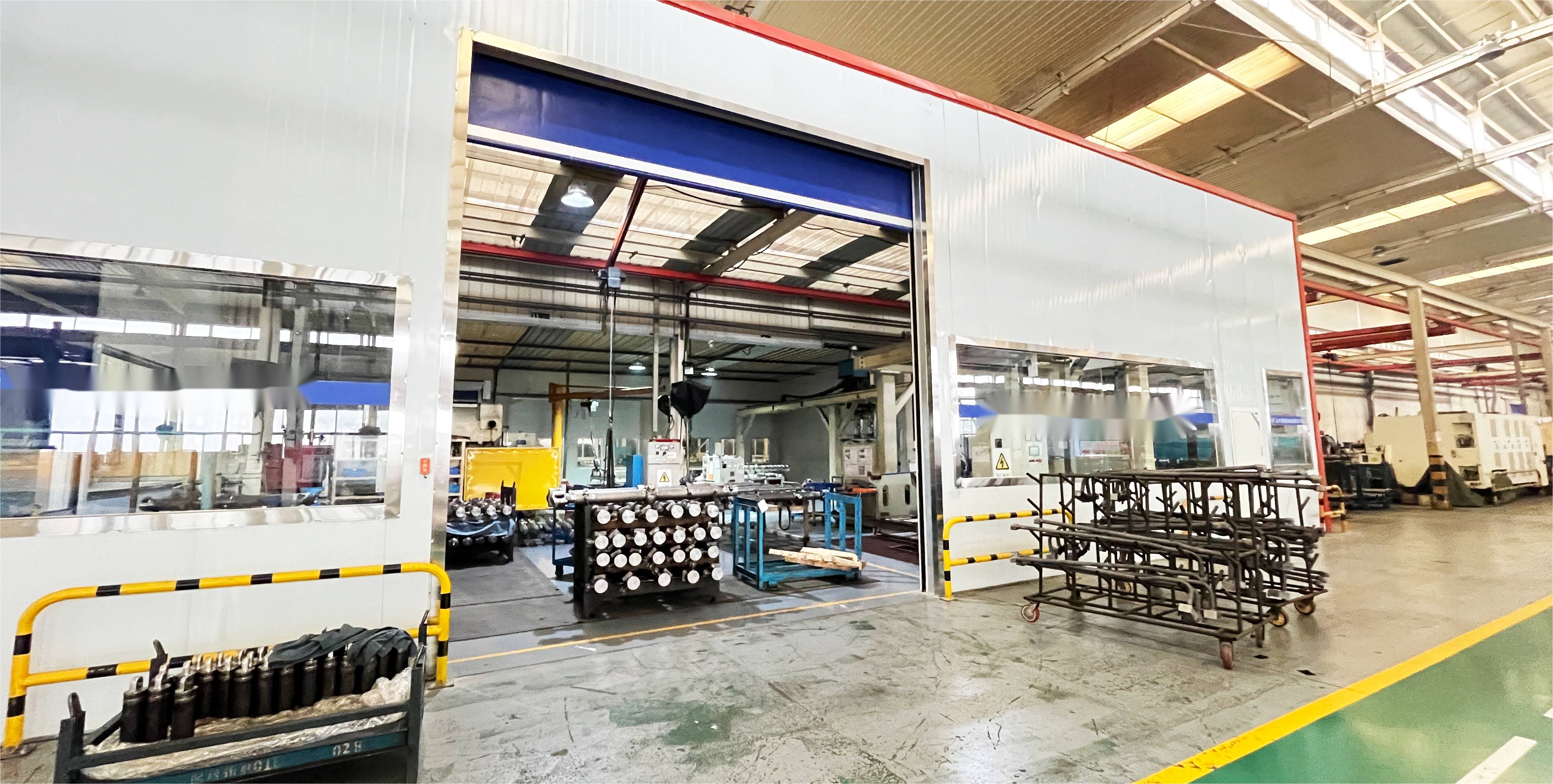
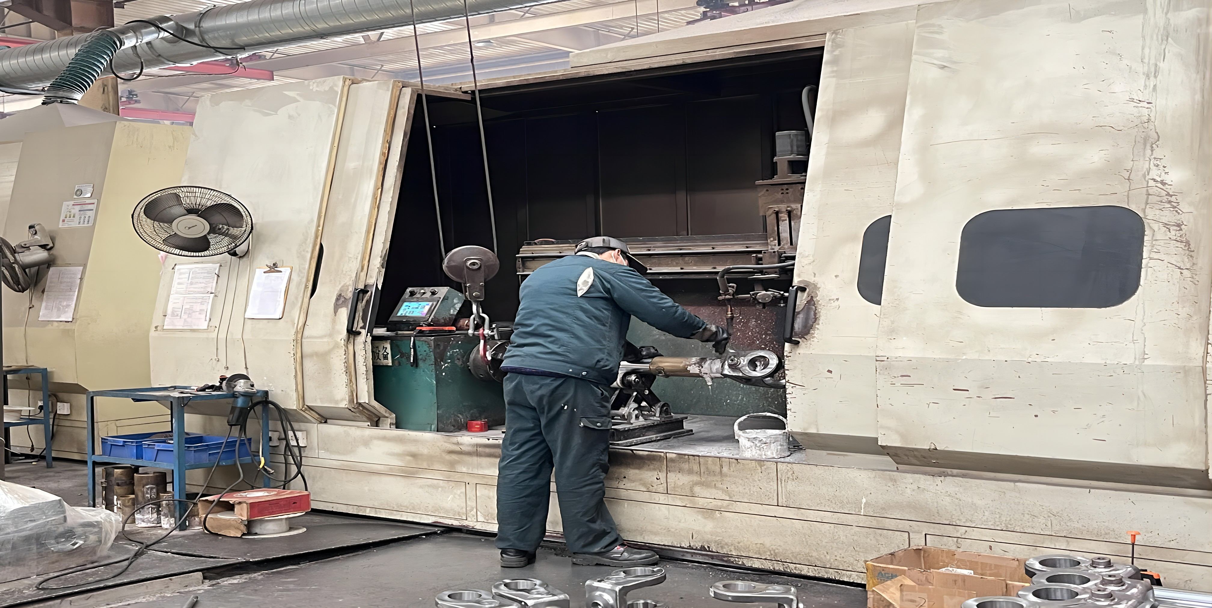
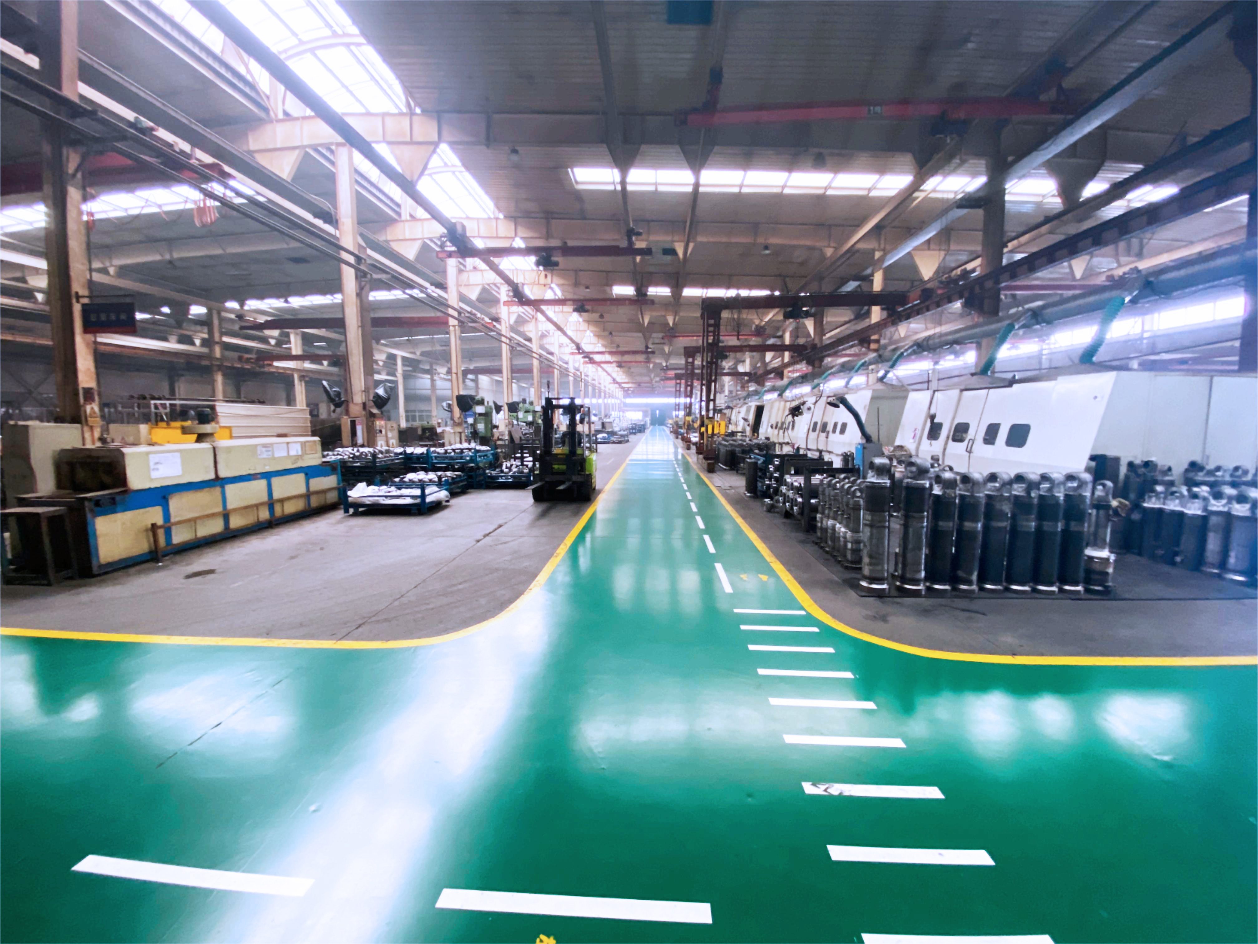
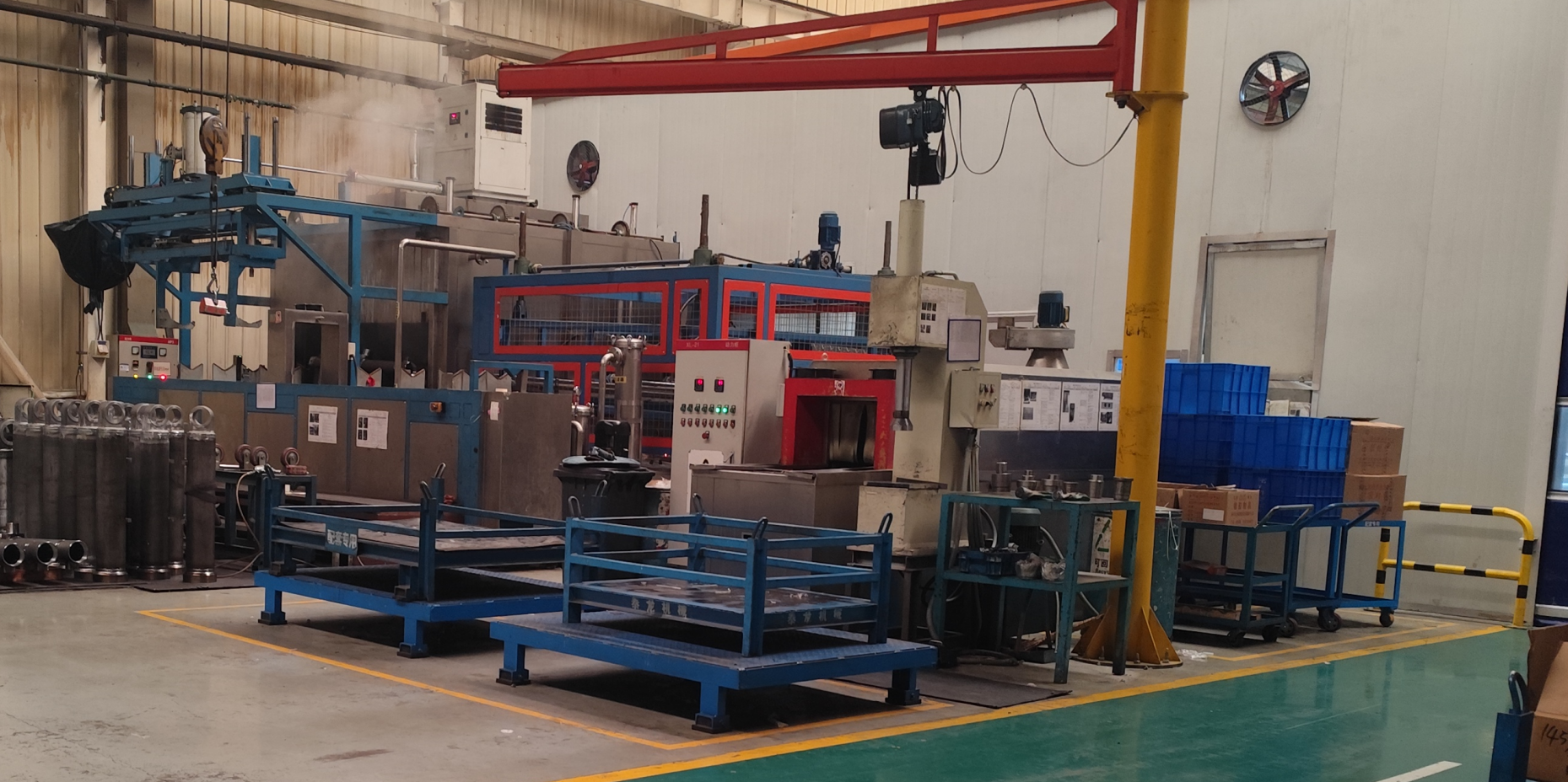
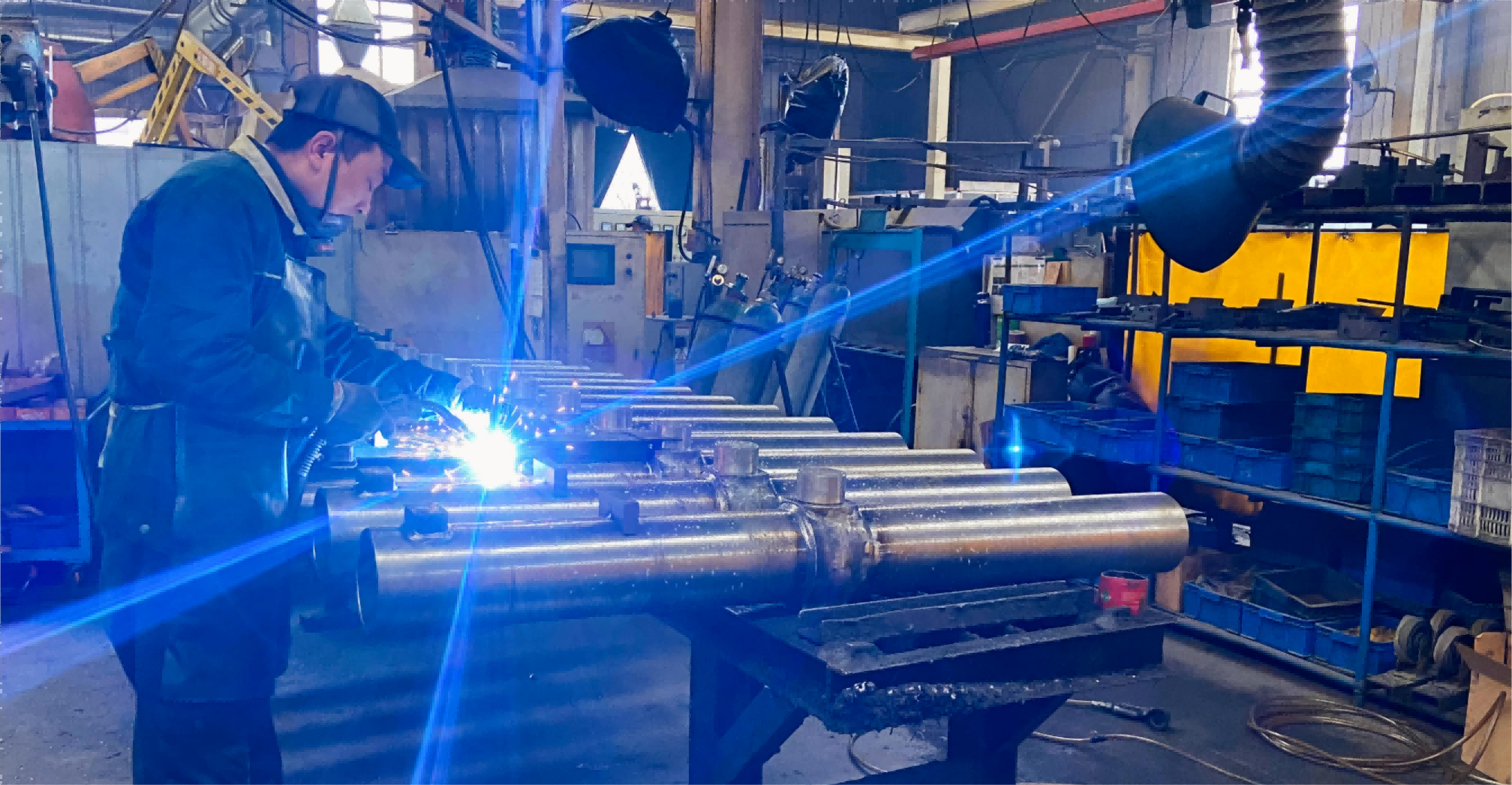
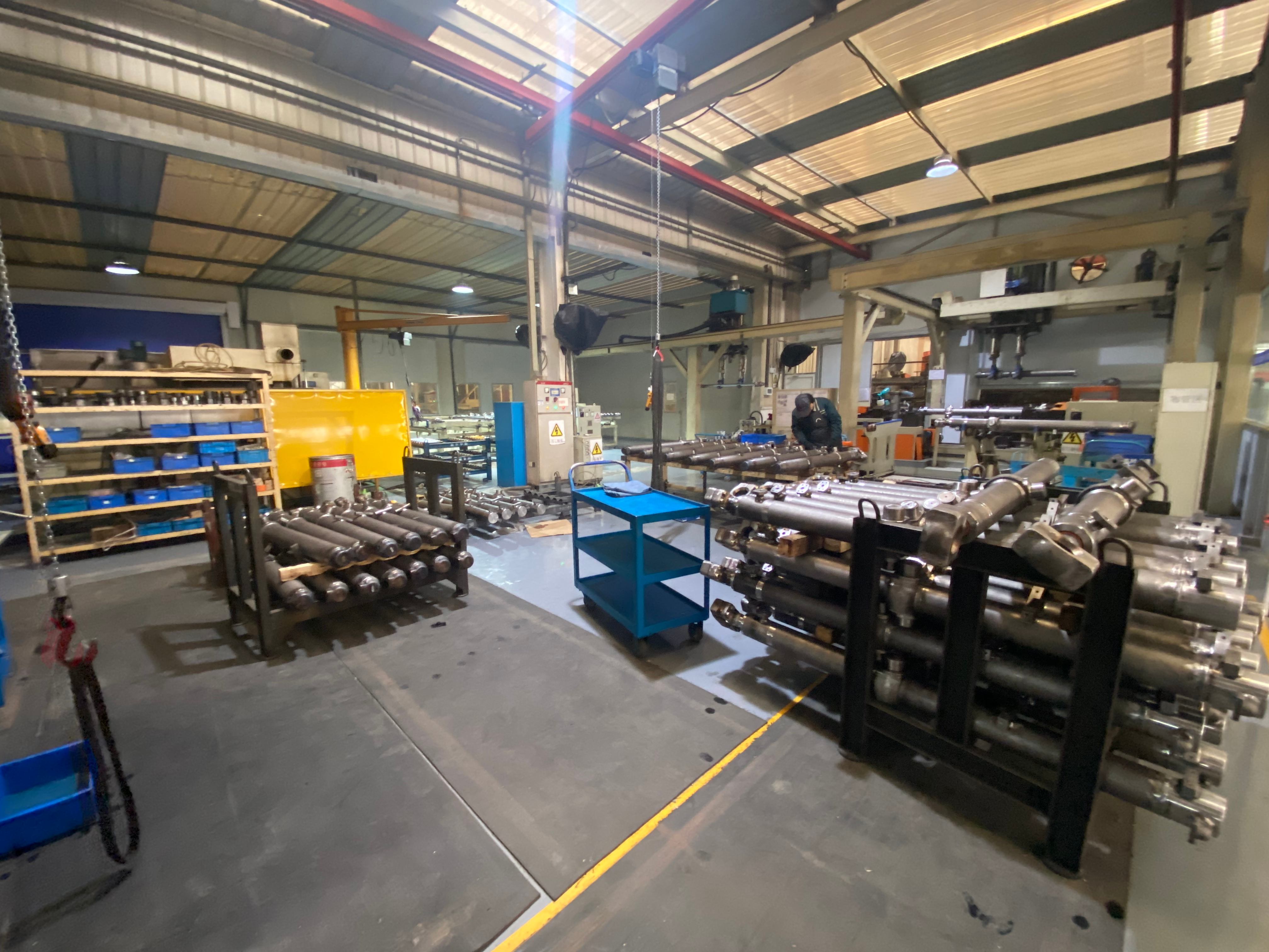
الشهادات والجوائز
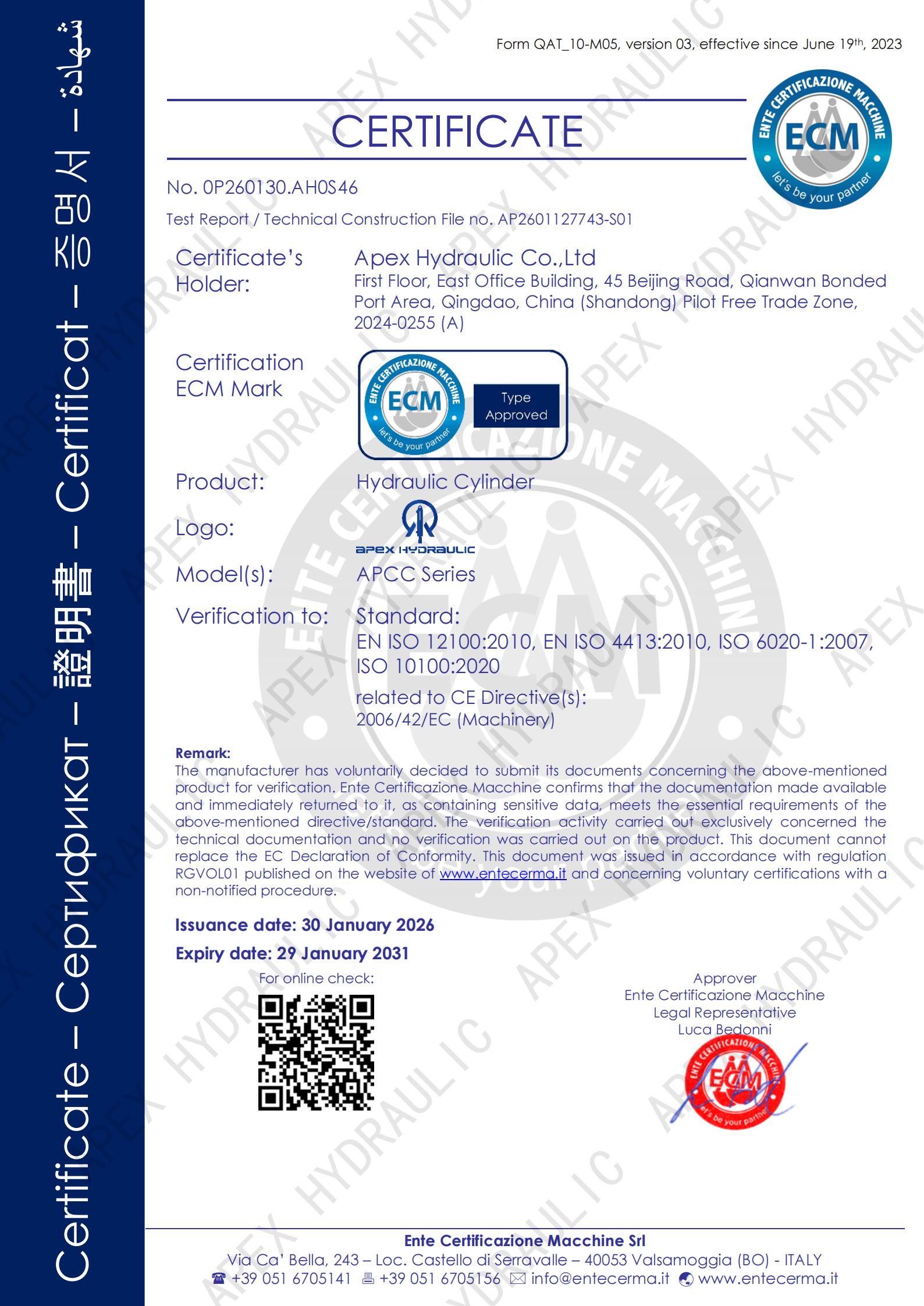
قصص النجاح
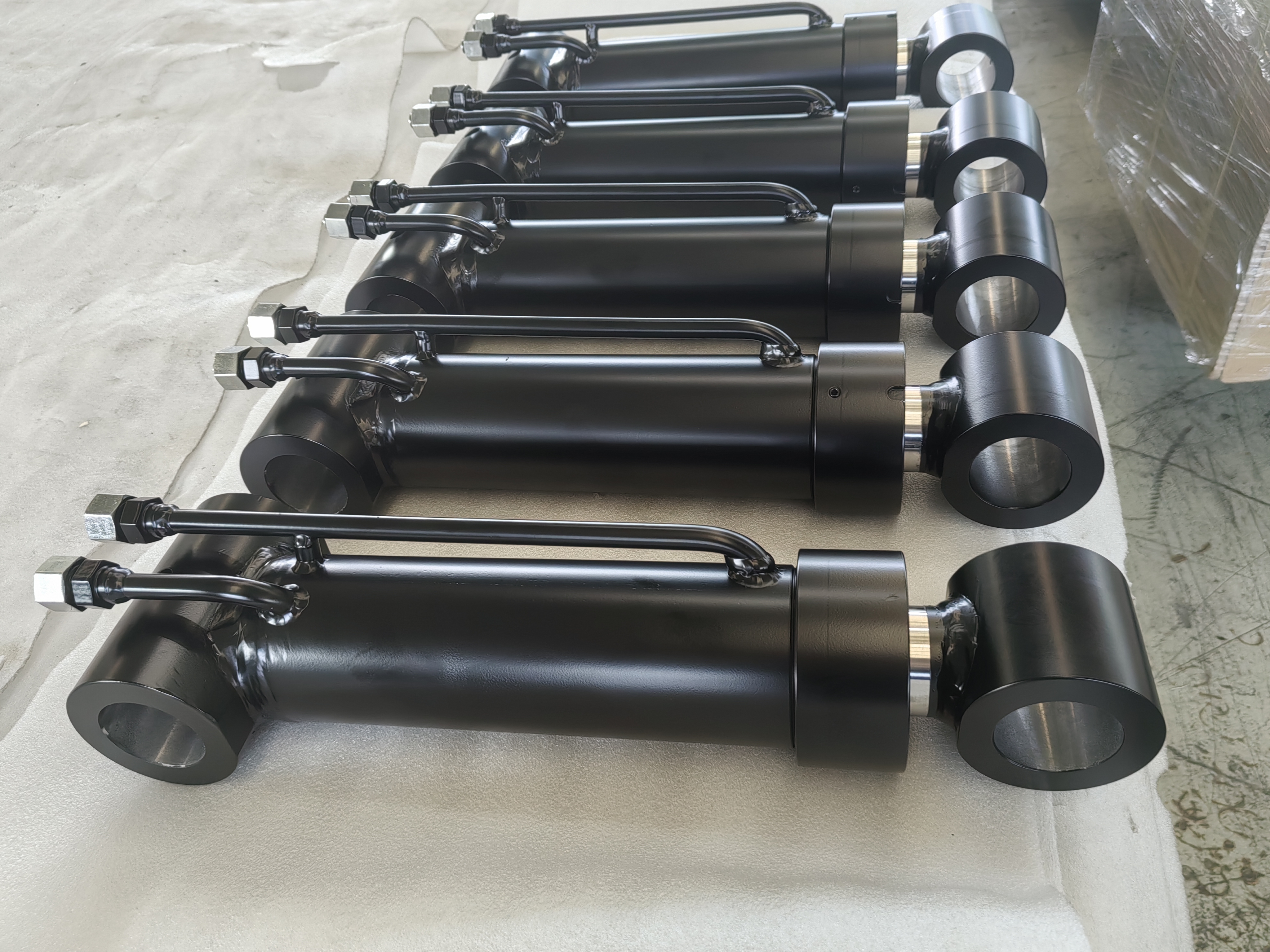
Hydraulic Grapple Equipment Manufacturer
Improved gripping force, enhanced operational stability, reduced maintenance requirements, and ensured reliable performance under continuous heavy-duty working conditions.
Fully customized hydraulic cylinder solution with optimized mounting dimensions, high-strength welded construction, heavy-duty sealing system, corrosion-resistant surface treatment, and long service life for demanding material handling applications.
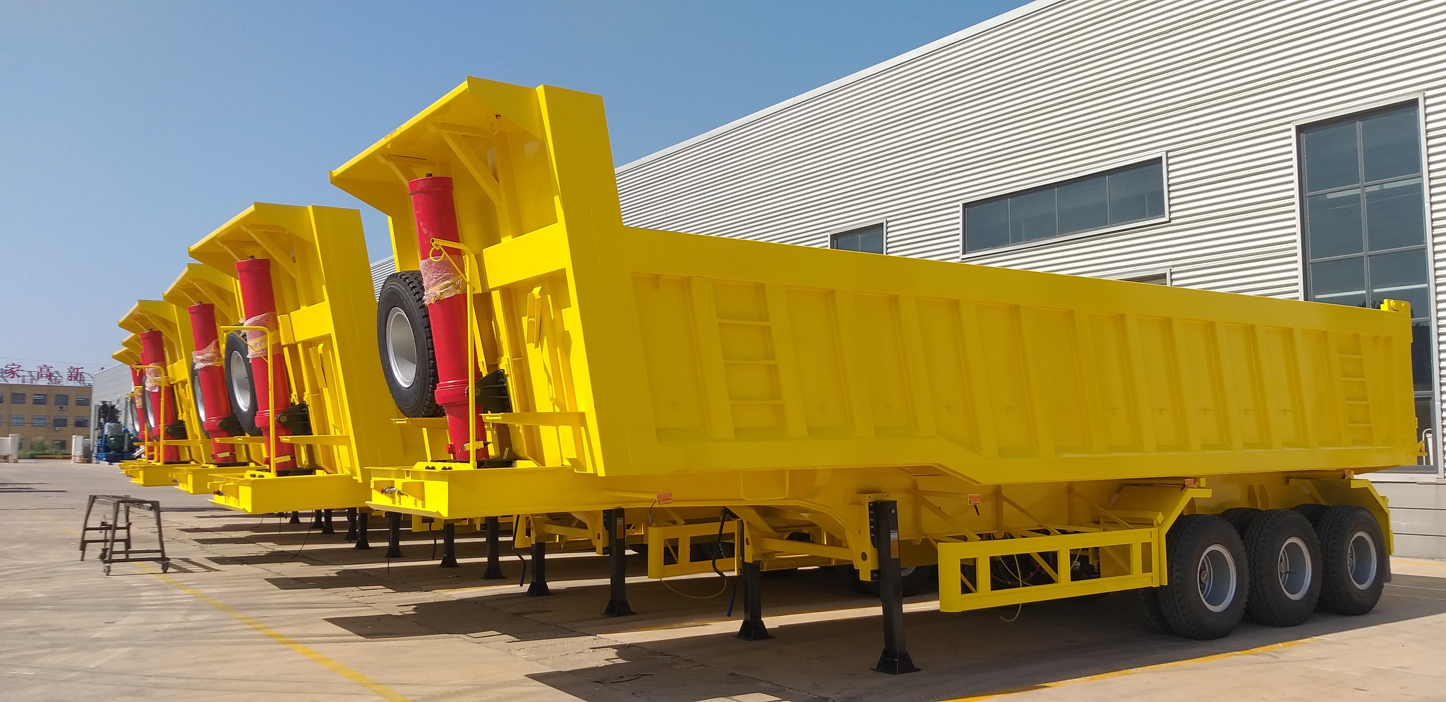
Heavy-duty Dump Truck OEM
Delivered reliable lifting performance, high operational efficiency, and excellent durability under continuous heavy-load working conditions.
High-strength multi-stage telescopic design with optimized sealing system, superior side-load resistance, and excellent fatigue life for demanding applications.
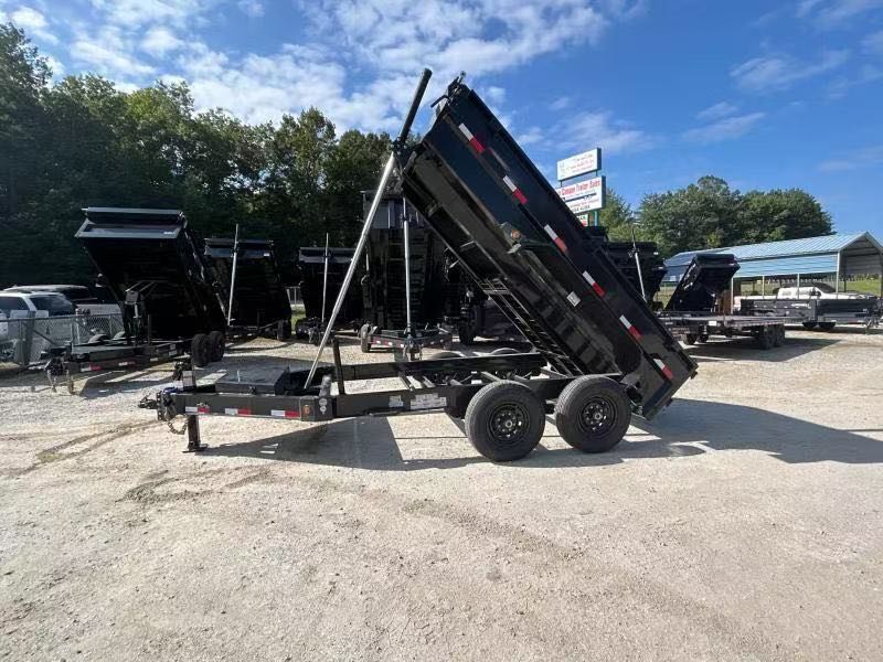
Dump Trailer Manufacturer
Achieved smooth lifting performance, stable dumping angle, and reduced service downtime while supporting continuous heavy-duty operation.
HTC Series single-acting telescopic cylinders featuring compact retracted length, long stroke, high lifting capacity, and compatibility with North American dump trailer standards.
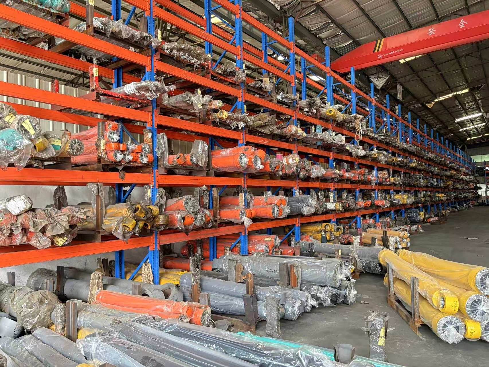
OEM Refuse Truck Manufacturer
Improved operational reliability, reduced maintenance frequency, and ensured stable performance under high-frequency waste collection operations.
Custom-engineered hydraulic cylinders with heavy-duty welded construction, high-pressure sealing system, corrosion-resistant coating, and long service life under demanding municipal operating conditions.
مقاطع فيديو الشركة والمنتجات
مقدمة عن الشركة وجولة في المصنع
⏱ Duration: 3:45 | 👁 Views: 15,230
عرض المنتج - Kestrel K-1
⏱ Duration: 5:12 | 👁 Views: 28,450
عرض الابتكار التقني
⏱ Duration: 4:30 | 👁 Views: 12,890
شهادات العملاء وقصص النجاح
⏱ Duration: 6:20 | 👁 Views: 9,650
هل أنت مستعد لتغيير حياتك؟
اتصل بنا الآن لتعرف كيف تلبي منتجاتنا احتياجاتك.